PCB for building the JLM Hybrid opamp with high current output drive transistors. It can have the output transistors set to run in Class A/B or Class A Mode. It also has on board DC Servo that can be enabled by soldering two solder pads together under the PCB. It is pin compatible with the JLM99v , 990, 992 , 993 , MM99, 2520. Sound wise in class A/B the opamp is fast and transients snap at you. In class A the top end softens down and sounds silky a bit like the 99v but with super tight low end.
Can be used in precision Mic pres, EQ gyrators, virtual earth summing stages, headphone amps, balanced in receivers and output drivers.
JLM Hybrid opamp circuit PDF
Specifications
- 1.1" x 1.1" PCB
- THD = 0.008%
- Min Load = 50ohm
- Maximum power rails = +/-24vdc
- Idle Current in class A/B = 10to 12mA
- Idle Current in class A = 25mA to 30mA
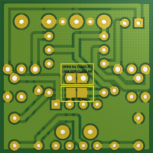
Solder Links on back of Hybrid PCB to Set Class A or AB and DC Servo.