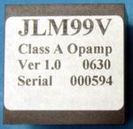
JLM99v opamp
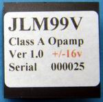
New JLM99v +/-16v version
JLM Go Between & DI PCBs & Kits
JLM1:4 Mic Input
JLM1:1:1DC output
Built JLMSW.PCB
JLM Dual 16mm 10k Reverse log pot with 41 detents. |
JLM99V Opamp and PCB & Kit 
Links to some of the full Forum threads
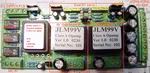
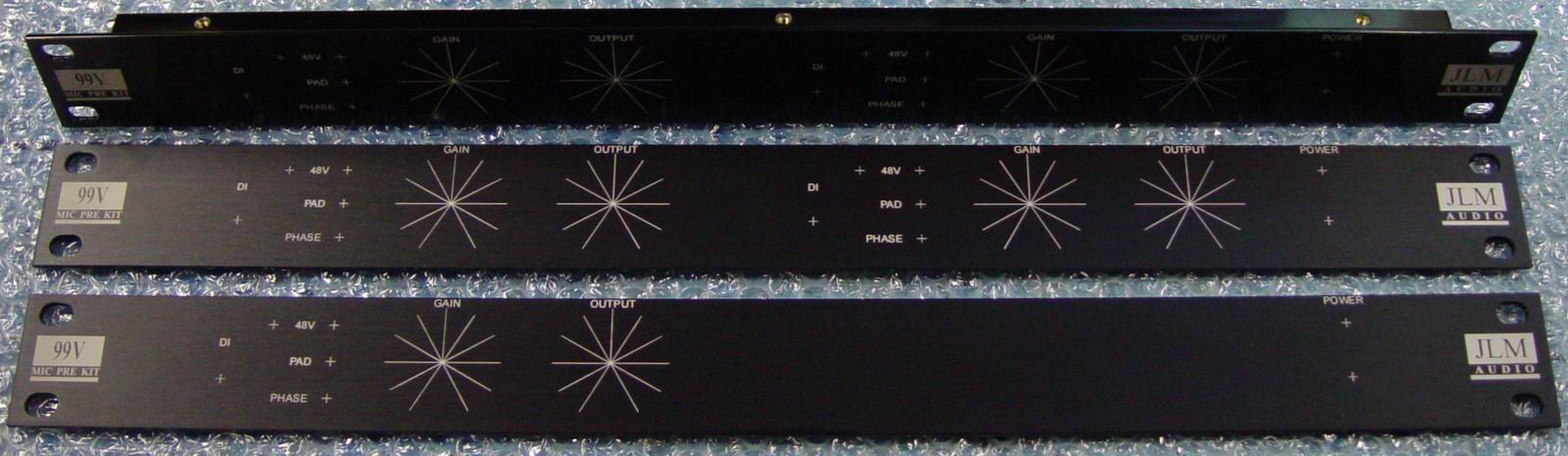
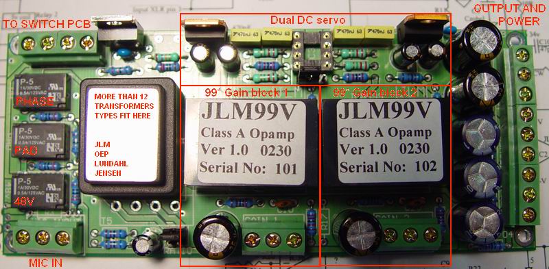
JLM99*MB is 5.45" (139mm) x 2.3" (59mm). Above is the JLM99*MB PCB for the JLM99V which can take several transformers from manufacturers like OEP, Lundahl & Jensen. The board also has NE5534A DIP8 sockets so it can be fully tested with cheap IC's before installing the 99V. The PCB can be used for building the simplest NE5534A or 99V circuit or all the way up to dual 99V with dual DC servo. PCB has provision for 3 pushbuttons switches or relays for 48v, PAD & Phase on one edge. The relays run from a constant current source so more relays can be easily wired in series for extra features without making noise on the audio power rails. The small PCB is the JLMSWMB which takes three toggles and LED's to control the relays if used by 4 wires.
JLMSW PCB is 1" (25.4mm) x 1.3" (32.7mm) with toggle holes spaced at 0.5" (12.7mm).
The terminal blocks have tongue and grooves which lock them together on there sides. So 2 x 2 way can make the 4way and 3 x 3 way can make the 9way. If you don't join them together they will sit uneven on the PCB.
Normal 8 pin DIP IC sockets and comp cap for NE5534A
etc can be left on the PCB if PCB pins are used for the JLM99V
If you can not open the PDF's below you will need Acrobat reader 7.0.
Input Transformers the PCB can take directly are
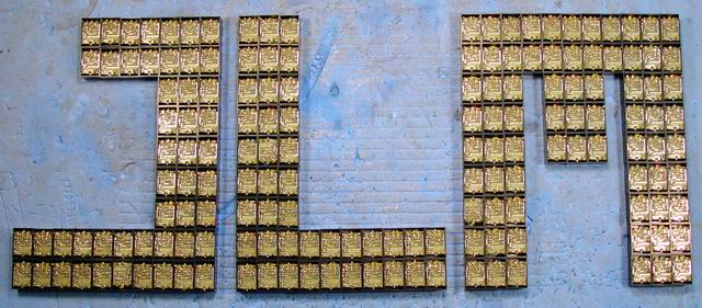
Just for clarity 200 x
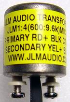
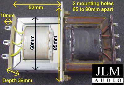
JLM99V's just before being epoxy potted and final testing. New JLM111DC Output transformer. Can be used for Neve LO1166 or API 2503 type DIY projects. The transformer is DC gapped and has 3 identical 150ohm windings that are trifilar wound. So can use as 1:1:1 or 1:2 or 2:1 applications. It is physically the same size as the LO1166 except the the top terminal plate is narrower so it will fit on its side in 1 unit high racks which have a 38mm internal height. Each winding has its connections opposite each other and one side is marked Red+ and the other Yellow-.
|


