- JLM World Power
transformer kit, AC/DC (Ver. 2) 3 rail kit &
Power Station (Ver. 2) 5 rail kit & 24v Simple Zener Reg Power Supply kit
building info below
Kit Reviews here
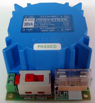
- JLM
World Power kit is a fully fused & 120v/240VAC switchable 30VA PCB
power transformer to dual low voltage AC out.
- Kit can be ordered with 3
different transformers with either 2 x 9vac or 2 x 12vac or 2 x 15vac
outputs.
- This kit with either a AC/DC
or Powerstation kit will give you a full power supply solution that will
work anyway in the world.
- The
World Power PCB is 3.6" (91.5mm) wide x 2.5" (63.5mm) deep x 1.575" (40mm)
high with 30VA transformer fitted.
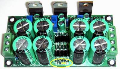
- JLM AC/DC
Ver. 2 kit is a Linear
based universal power supply with can generate 3 voltage rails from a single or
dual 24 to 30vac.
- It has one pump charge rail for 48vdc, 1 +/- Rails that can be
set from +/-2v to 37v by a 25turn trim pot.
- All regulators are on one edge for
easy heatsink or case mounting.
- Can supply 1amp per +/-V
rail and 300mA +48vdc. 1amp for +/'-V rails can be boosted to 1.5amp with 4
extra 1N4007 diodes.
-
The AC/DC Ver. 1 & 2 PCB is 3.3"wide (83mm) x
1.7"deep (43mm) x 1.1" (28mm) high from top of tallest cap to lowest solder
joint under the PCB.
-

- JLM Power Station
Ver. 2 kit is a Linear based universal power supply with can generate 5 voltage
rails from a single or dual 24 to 30vac. It has one pump charge rail for
48vdc, 2 +/- Rails that can be set from +/-2v to 37v by a 25turn trim pot.
- All regulators are on one edge for easy heatsink or case mounting.
- Can supply 1amp total shared
between both +/-V rail and 300mA +48vdc. 1amp total for +/-V rails can
be boosted to 2amp with 4 extra 1N4007 diodes.
-
The Power Station
Ver. 1 & 2 PCB is 4.06" wide
(103mm) x 1.7" deep (43mm) x 1.1" (28mm) high from top of tallest cap to lowest
solder joint under the PCB.
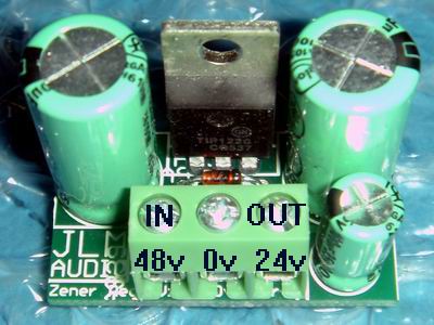
- JLM
Simple 24v zener kit is a very simple Linear based universal power supply with can generate
24v from a single 30v to 48vdc rail.
- It can do other output
voltages by changing to different voltage zeners or if running from a
regulated higher rail a resistor can be used in place of the zener.
- Using on of the 48v 380mA
SMPS prebuilt supplies and a simple zener kit is the easiest and cheapest
way to power 2 x 1073 , 1290, 1272 neve modules.
- Or 2 x V672 modules etc that
need 24v to run and 48v rail for phantom power. Because there is no power
transformer involved there is no hum problems due to coupling to the audio
transformers.
- Regulator
is on one edge for easy heatsink or case mounting.
- Can supply 1amp
-
The simple zener PCB is 1.2" wide
(103mm) x 1" deep (43mm) x 1.1" (28mm) high from top of tallest cap to lowest
solder joint under the PCB.
- ALL 120/240v mains wiring MUST
be done by a Qualified Technician.
- What Power Transformer
secondary volts do I need?
- The transformer secondary AC
volts needed depends on the +/- dc regulated voltage rails wanted. If you want
+/-34vdc regulated for 99v you will need 37v to 40v unregulated which would need
one or two 26vac to 28vac transformer secondary windings. This might sound like
a odd voltage value but in reality when you take the fully loaded voltage and
add the regulation percentage specified by the transformer manufacture to get
the no load voltage it all works out. So if the voltage output of a transformer
is stated as 25vac at full load by adding the 10 to 20% regulation amount you
will end up with 27.5vac to 30vac unloaded with is perfect. Also if you use one
25vac winding then the refresh rate to the large storage capacitors will be 50
or 60Hz depending on the country you are in. If you use two 25vac windings or a
50vac centre tapped winding the refresh rate will be 100Hz or 120Hz which will
almost half the amount of ripple on the large storage caps. Also the dual 25vac
has symmetrical ripple.
- Step by step build for
PowerStation Ver. 2 and AC/DC Ver. 2 kits
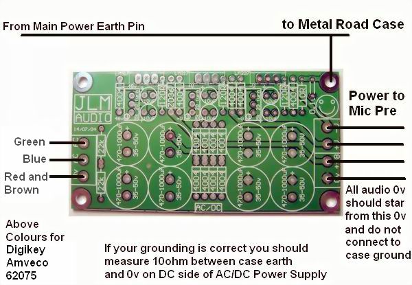
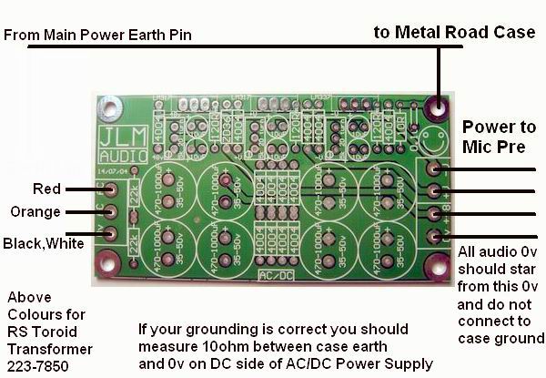
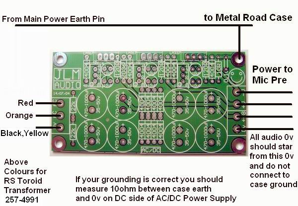
Below shows
correct Mains earthing and 0v connections which applies to AC/DC PCB and
PowerStation PCB
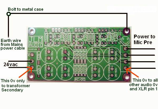
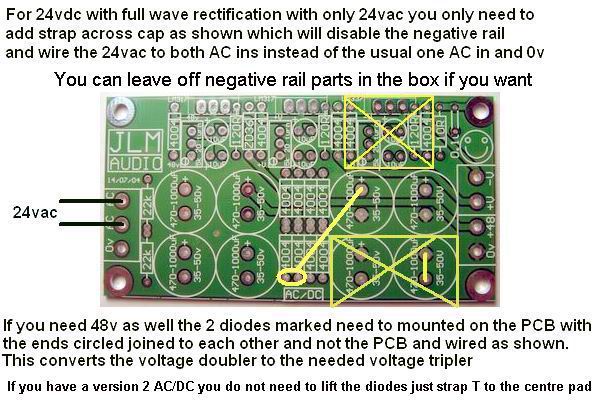
Below shows how to get +24vdc and +48vdc
from just a 24vac plug pack to run Neve or old Telefunken gear which requires no
negative rail. If using 2 x 22v to 2 x 25vac transformer no mod is needed and
negative parts can be left off.
Below shows shows colour code and
wiring for Digikey Amveco Toroid series of transformers.
Below shows shows colour code and
wiring for RS single mains voltage Toroid series of transformers.
Below shows shows colour code and wiring
for RS 120v/240v dual mains voltage Toroid series of transformers.
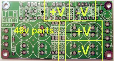
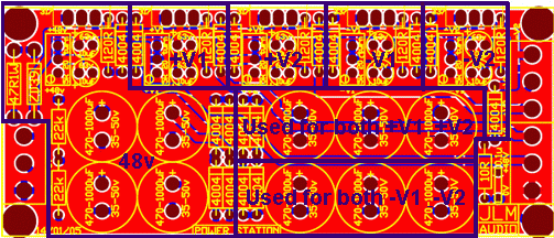
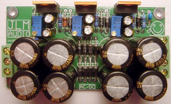
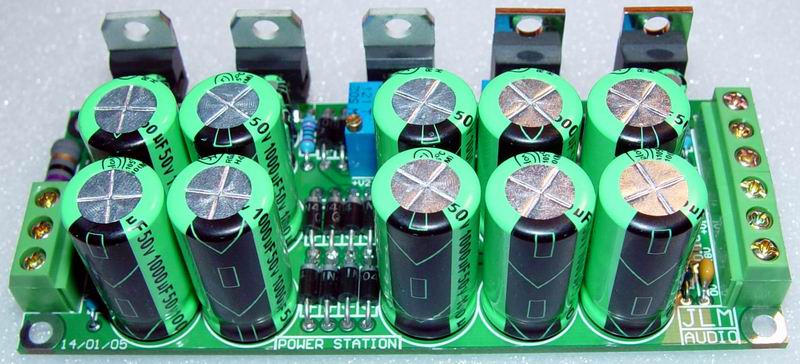
Old
Ver 1 AC/DC and Ver 1 PowerStation PCB's below are
Linear based universal power supplies with can generate 3 or 5 voltage rails from a
single or dual 24 to 30vac. It has one pump charge rail for 48vdc, 1 or 2 +/- Rails
that can be set from 5v to 34v by a resistor or 25turn trim pot. All regulators
are on one edge for easy heatsink or case mounting.
Old
JLML5RPSPCB below is a Linear based universal power supply with can generate 5
voltage rails from a single or dual 24 to 30vac. It has one pump charge rail for
48vdc, 2 +/- Rails that can be set from 5v to 34v by a resistor or 25turn trim
pot. All regulators are on one edge for easy heatsink or case mounting.
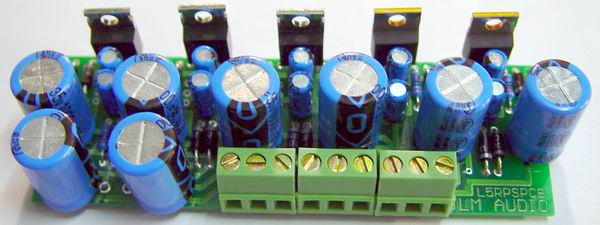
JLML5PSPCB is 4.3" (109mm) x
1.45" (37mm)
|
 Capturing Audio without Injury
 Capturing Audio without Injury