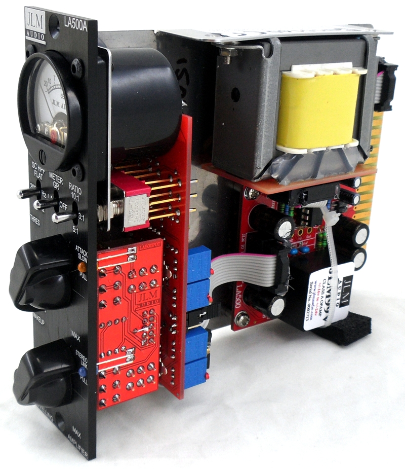
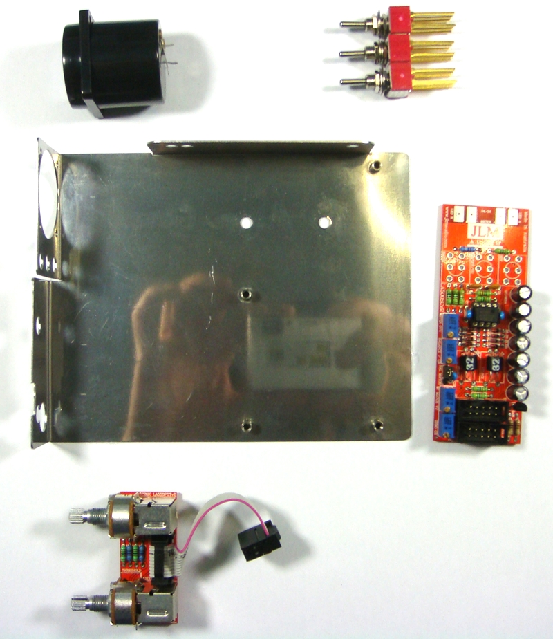
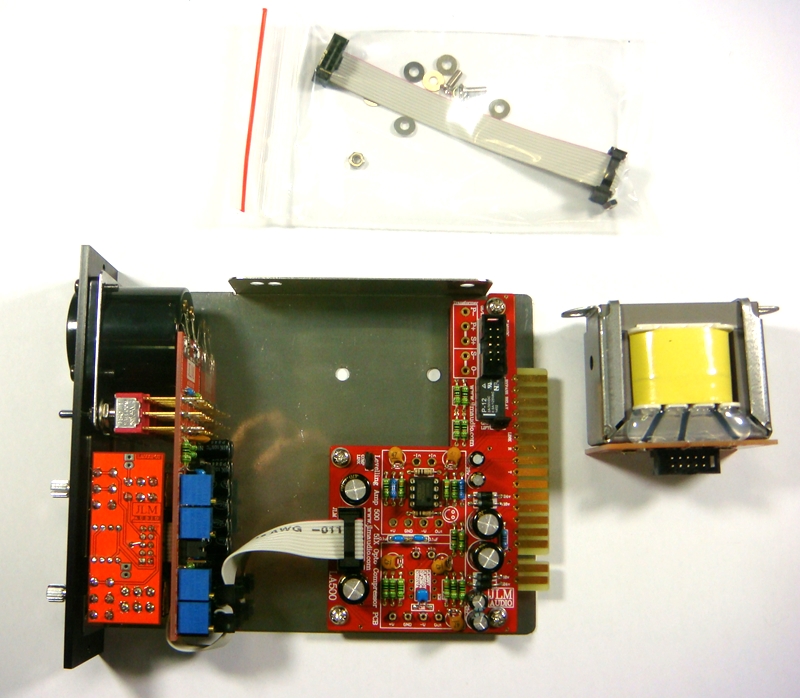
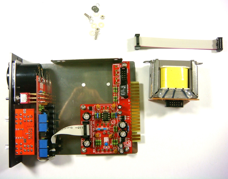
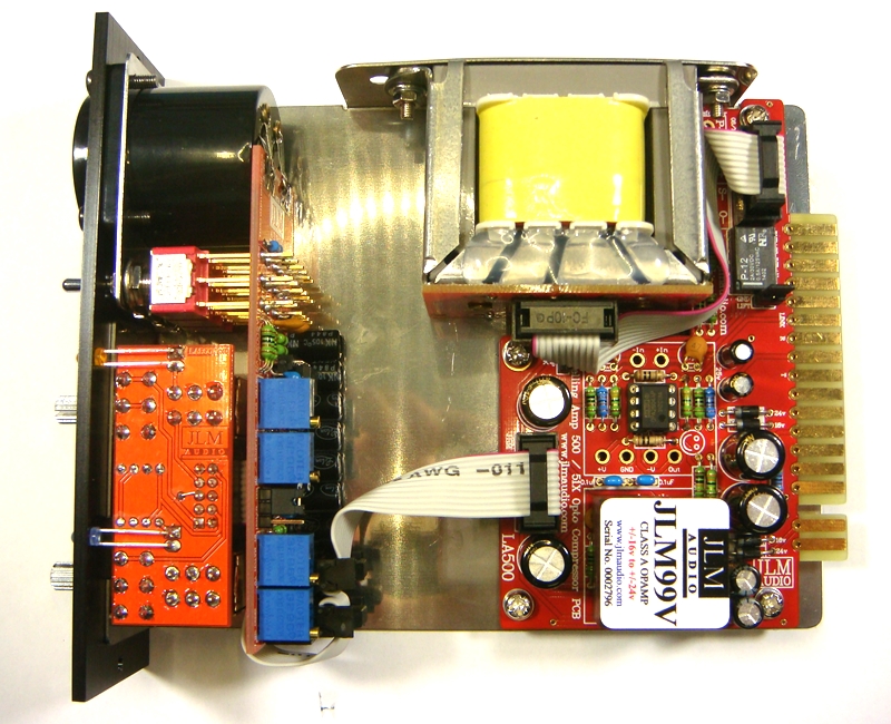
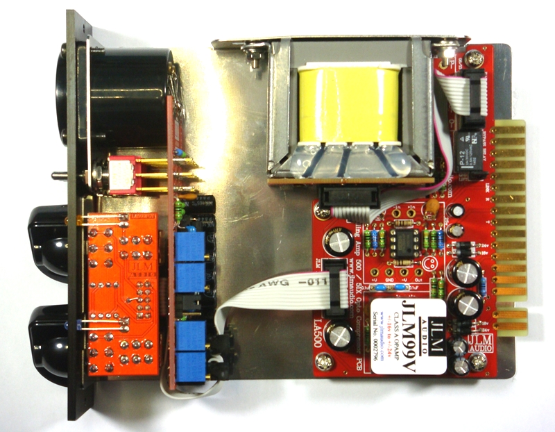
LA500A IMPROVEMENTS
3 PCB LAYOUT with no hand wiring just plug in 2 pre-made ribbon cables
NSL32 opto cells made for us to tighter tolerance spec.
Stereo Balance mod now a jumper on LA500SCv3 pcb so can be changed to in seconds.
Slow attack mod built in with leds for slow attack and stereo sidechain link.
78L05 reg so no zero GR adjustment needed between different 51X and 500 racks.
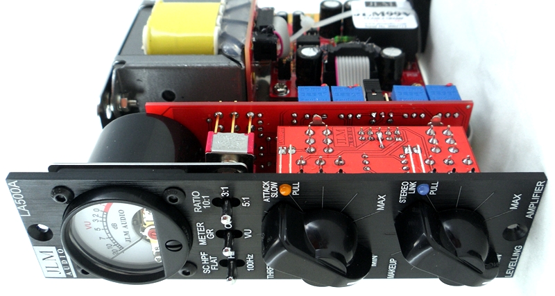
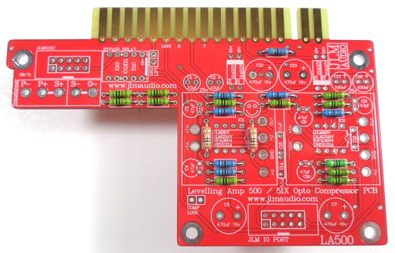
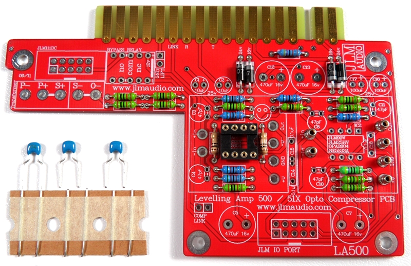
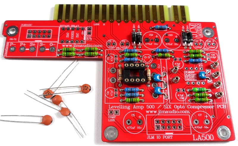
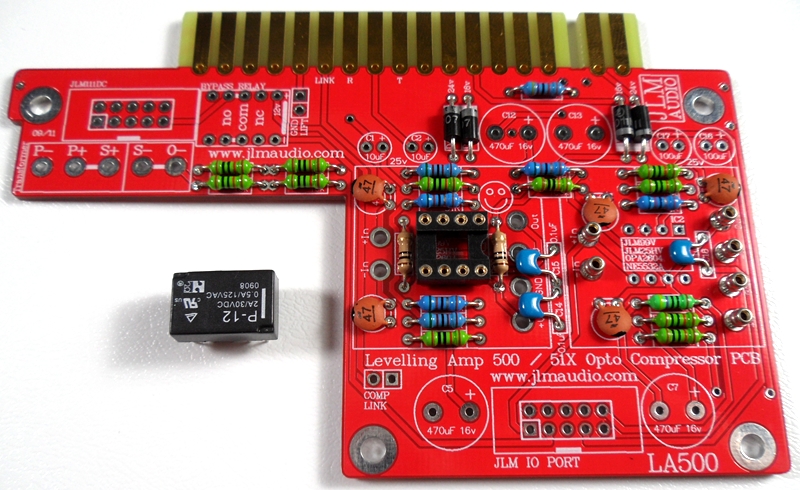
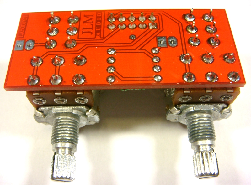
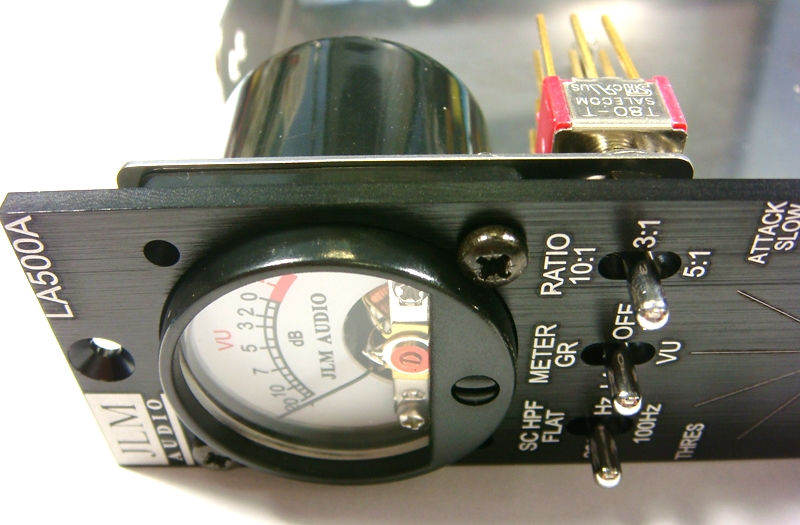
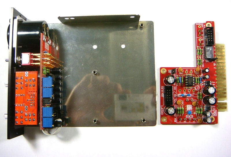
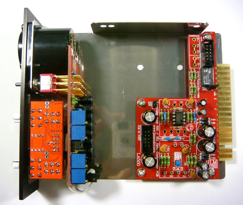
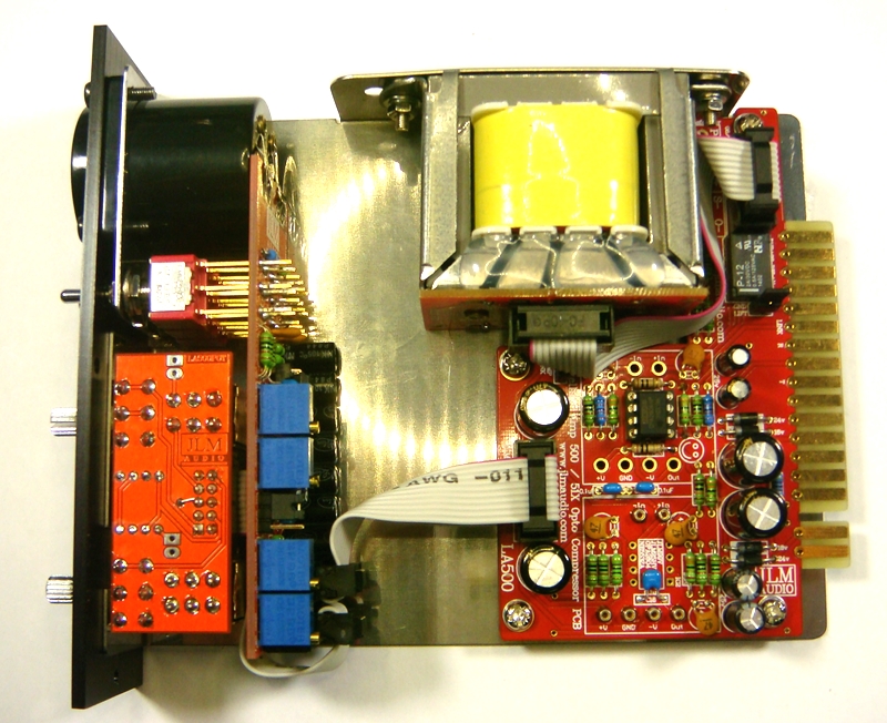
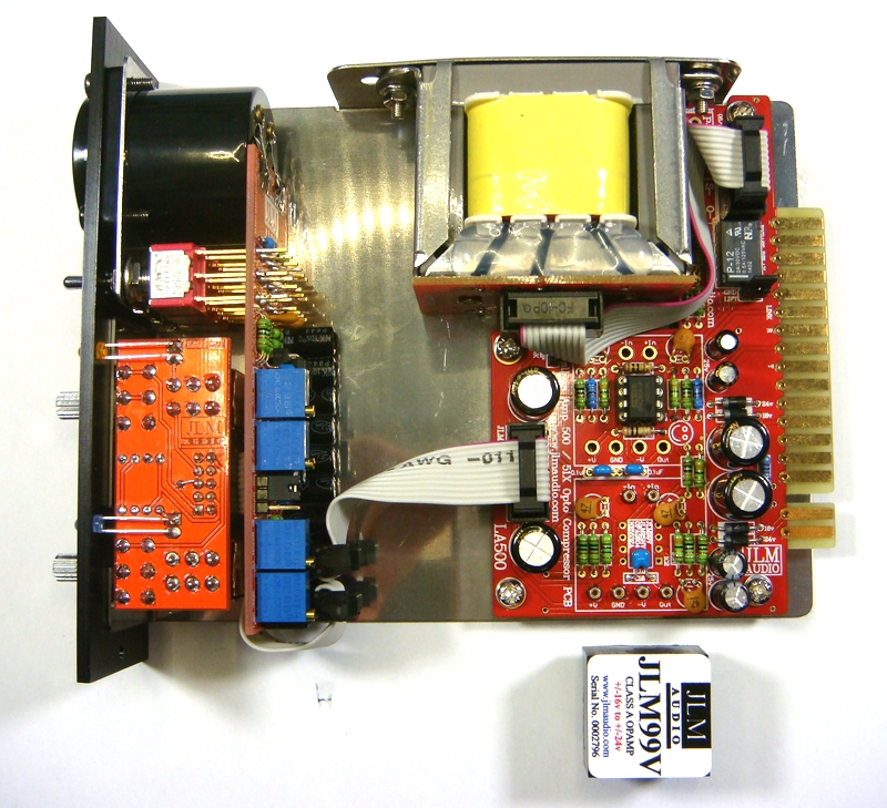
The LA500A is a 500/51x version of our well know MAC opto comp rack version.
For an idea on what the LA500 / MAC comp can do read this AT mag review here
LA500 recall sheet here

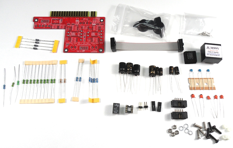
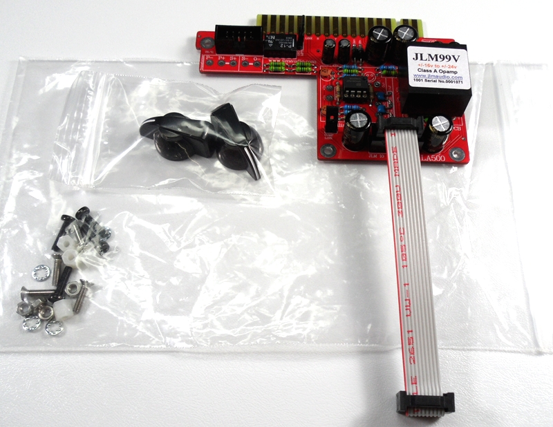
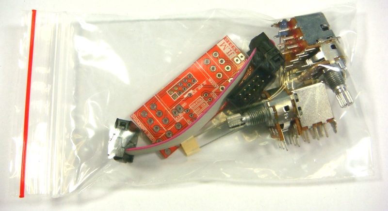
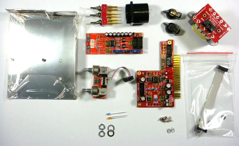
LA500A Parts List
http://www.jlmaudio.com/LA500A/LA500A%2 ... 20list.txt

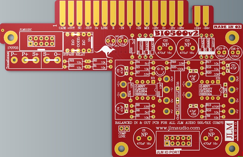
NEW BIO500v2 PCB schematic http://www.jlmaudio.com/BIO500/BIO500v2%20Schematic%20171007.pdf
OLD LA500/BIO500 PCB schematic http://www.jlmaudio.com/LA500/LA500%20Schematic%20120304.pdf
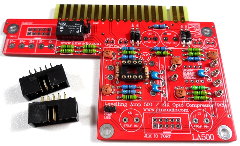
BIO500v2 PCB kit
1. Fully 51X and 500 compatible. 51X pins shorter so PCB will plug into 500 rack without having to cut them off.
3. PCB automatically uses highest power available. +/-16v for 500 and +/-24v for 51X.
4. LA500 PCB also has mix buss out on pin 11 for Radial Workhorse racks.
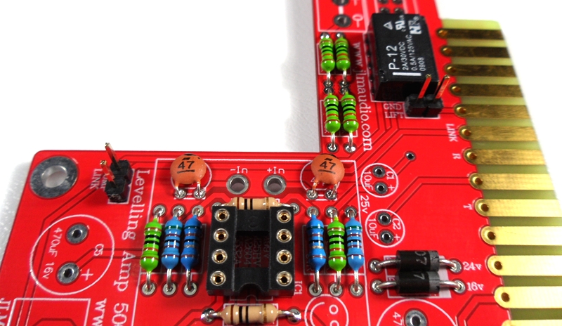
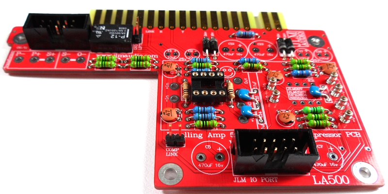
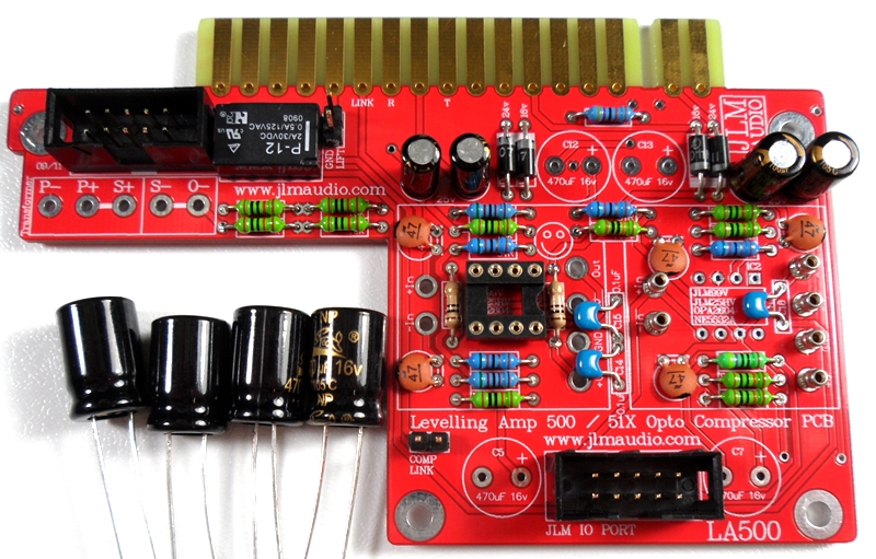
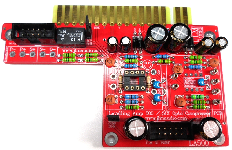
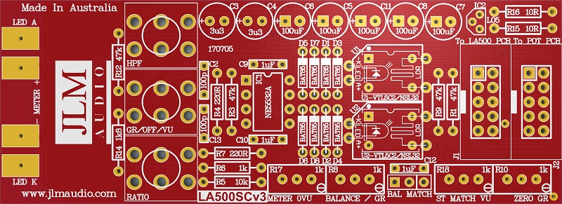
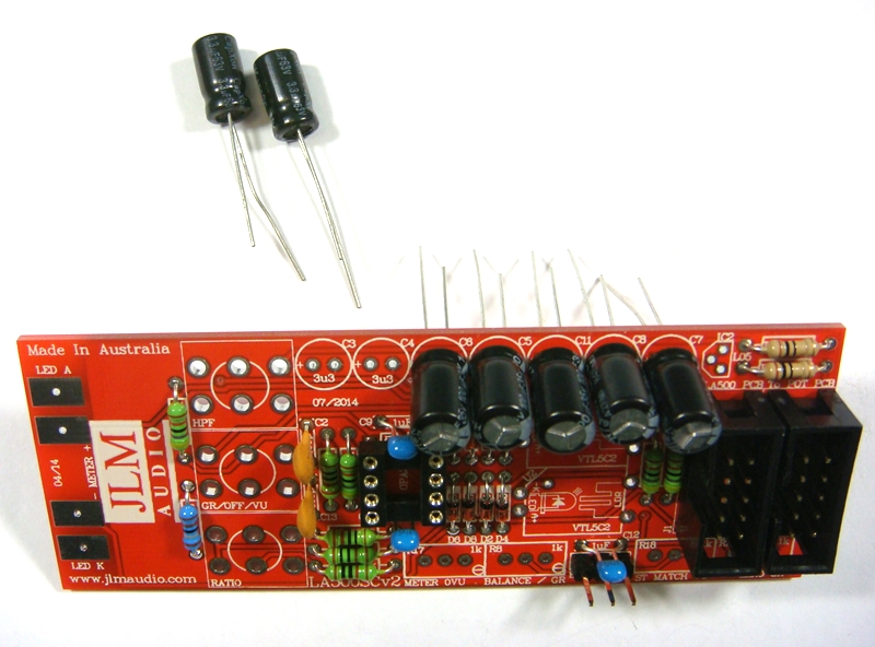
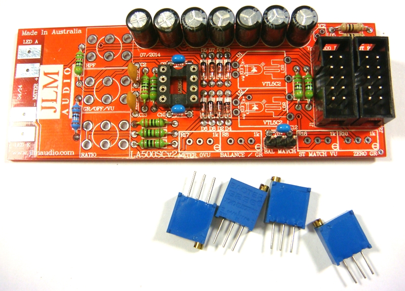
BIO500v2 PCB.
Notes and Errata
(LA500 PCB renamed to BIO500 PCB as it is used in several products as the Balanced In and Out PCB).
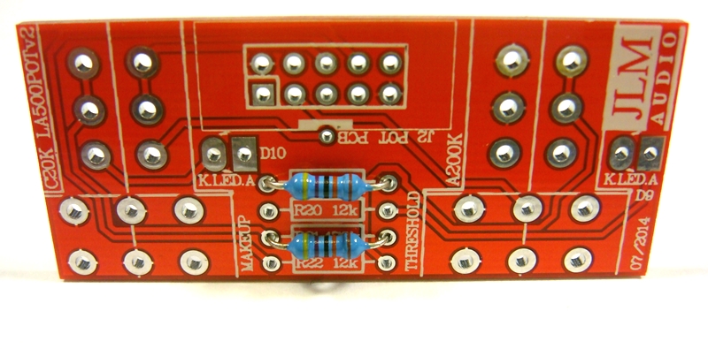
Note 1. Changed R19 51R to 33R give better low frequency response when using JLM111DC and JLM111DC compact output transformer
Note 2. Changed R4 and R6 10k to 5k1
Note 3. Changed R26 4k7 to 5k1
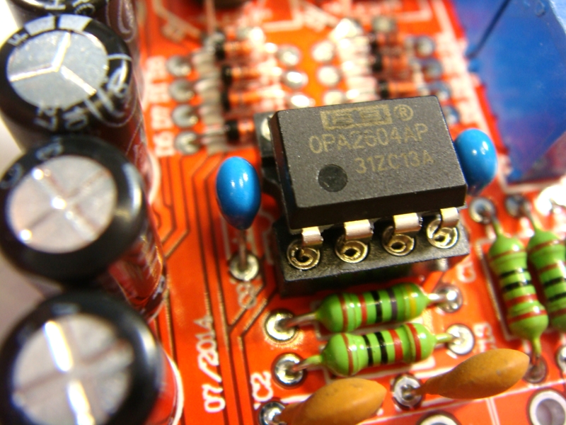
Note 4. Changed OPA2604A to NE5532A. As OPA2604A is now obsolete
Note 5. Added D5 & D6 2 x 3v3 zener diodes so NE5532A runs on 51X power rails
Note 6. Ground Lift pins removed from pcb as most 500 racks short this to 0v so does nothing
Note 7. Comp Link pins do not need to be fitted as the 2 pads are linked on the PCB now
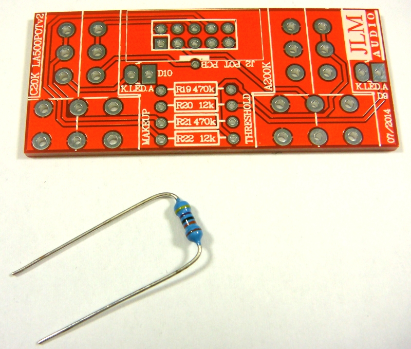
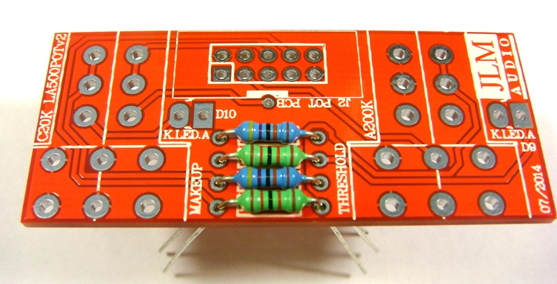
If you are not 100% with resistor colour codes use a multimeter to check values as you place the resistors
Fit all resistors at once bending the legs sightly outwards to hold them in place. This helps to make sure no resistors are put in the wrong position.
Solder all resistors while holding PCB firmly upside down on flat surface.
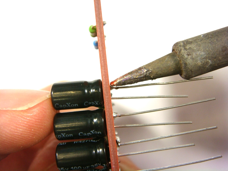
Cut all resistor legs off at top of the solder joint and double check no solder joints missed soldering.
Fit the 4 x 1N4007 diodes (& 2 x 3v3 Zener diodes BIO500v2). D1 to D6 Diodes are POLARIZED and must go in with there stripe matching the strip on the PCB overlay.

Solder diodes in once you have checked there POLARITY is correct.

Fit 6 x 1mm sockets for 99v opamp. Do NOT press the sockets in. Just let them sit in the holes. Use a piece of cardboard to hold them in while turning the PCB over.
Solder 6 x 1mm sockets in place
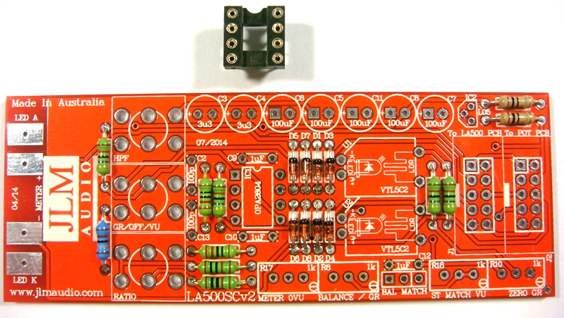
Fit and solder DIP8 socket in other opamp position. Make sure the POLARIZED socket matches the PCB overlay.
Fit and solder 3 x 0.1uF MONO caps in place. The 100nF caps are NOT Polarized so can go in either way around.
Caps should be marked 104 or 0.1u or 100n.
27th Dec 2015 a batch of kits has been packed with wrong value 102 1nF caps these will work fine for C14 & C15 but C18 will need to be 104 or 100nF or 0.1uF or larger. Can be any type of mono ceramic or MKT cap as it is only for the meter.
If C18 is smaller than 100nF you will not be able to calibrate the VU meter.
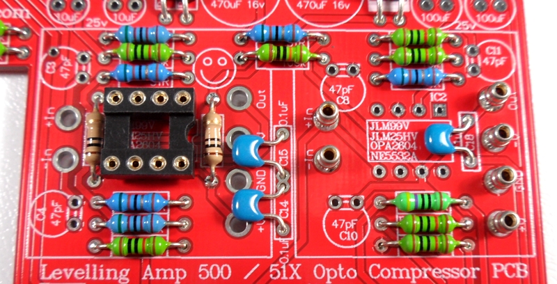
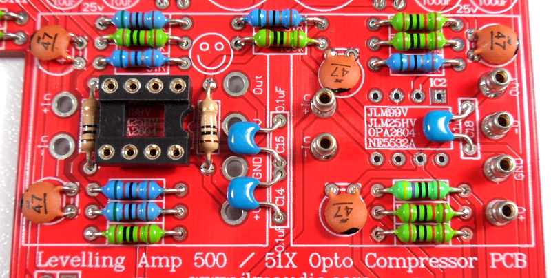
Fit 5 x 47pF ceramic caps in place. The 47pF caps are NOT Polarized so can go in either way around.
Fold 47pF caps down flat to PCB before soldering them.
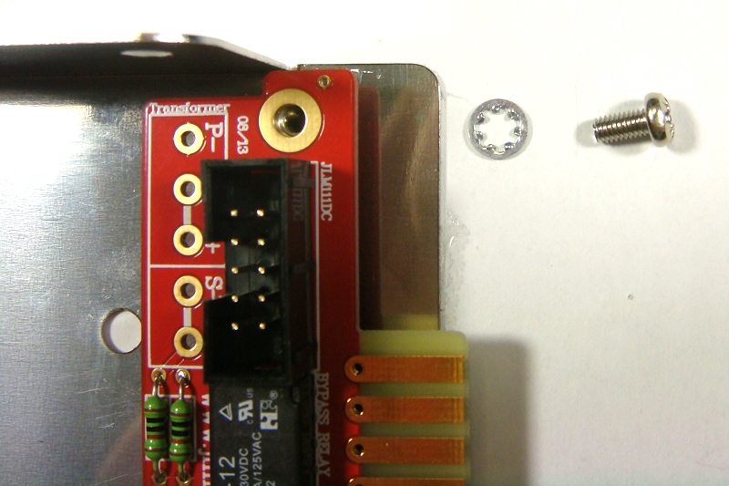
Fit 12v relay in the POLARITY shown in the photo.
Bend 2 legs out to hold relay in place for soldering
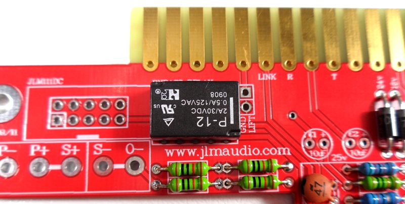
Solder relay in place once POLARITY has been checked
Fit and solder jumper pins in place (Not needed or fitted on Ver 2 PCB.)
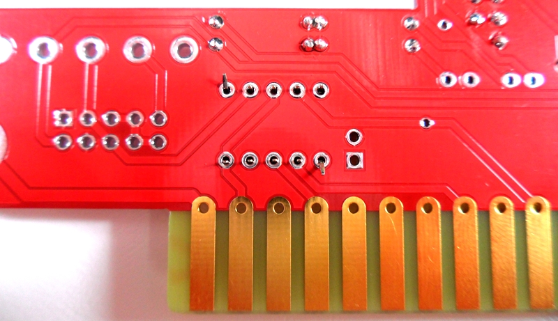
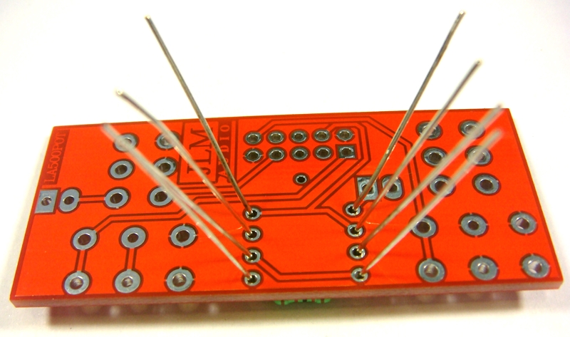
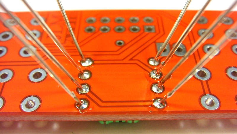
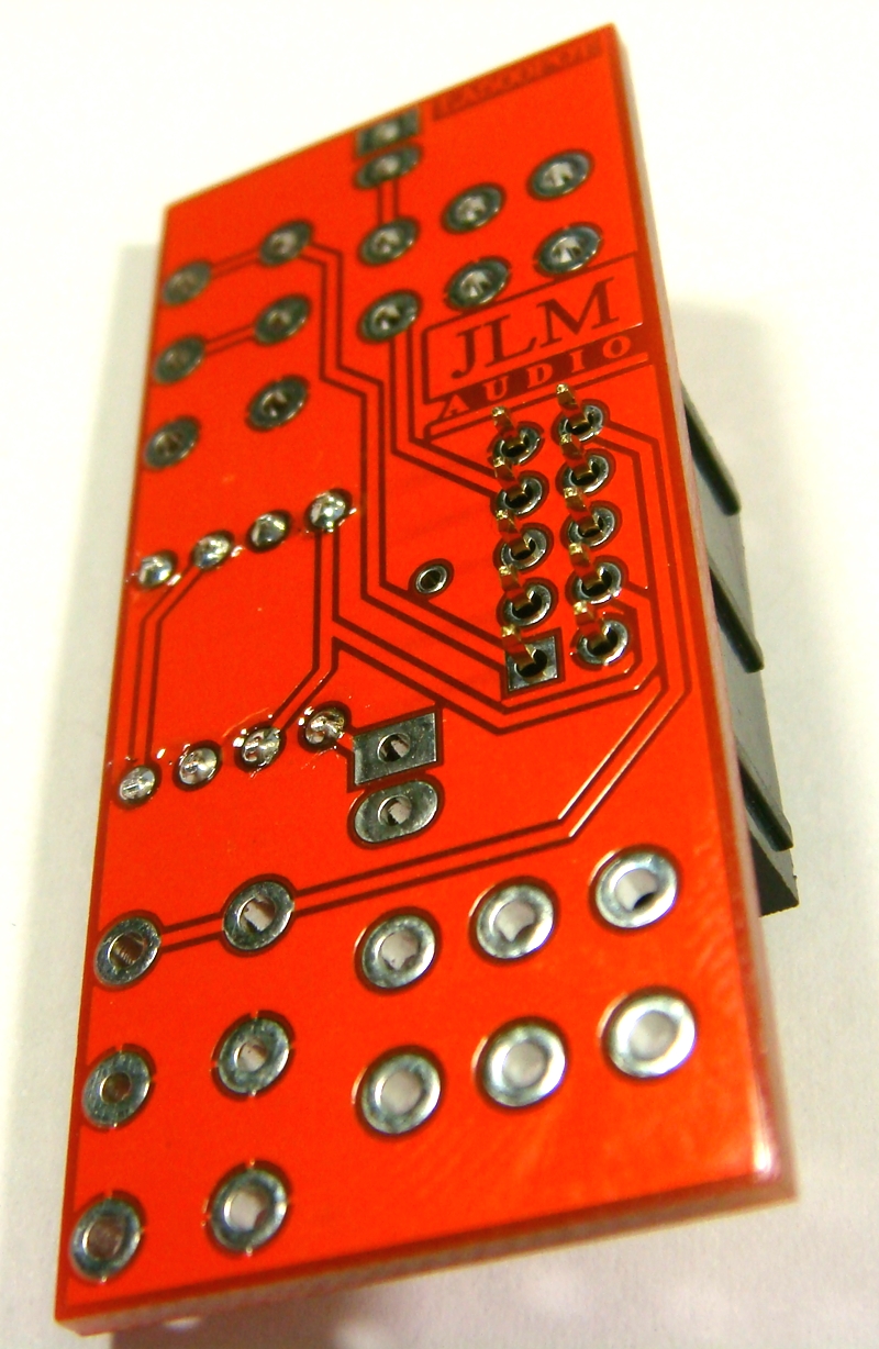
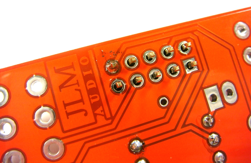
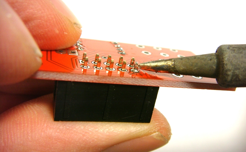
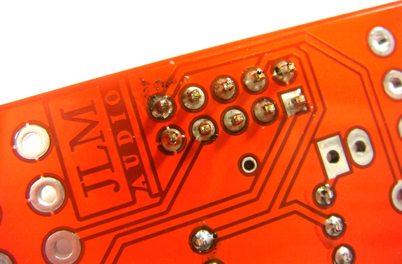
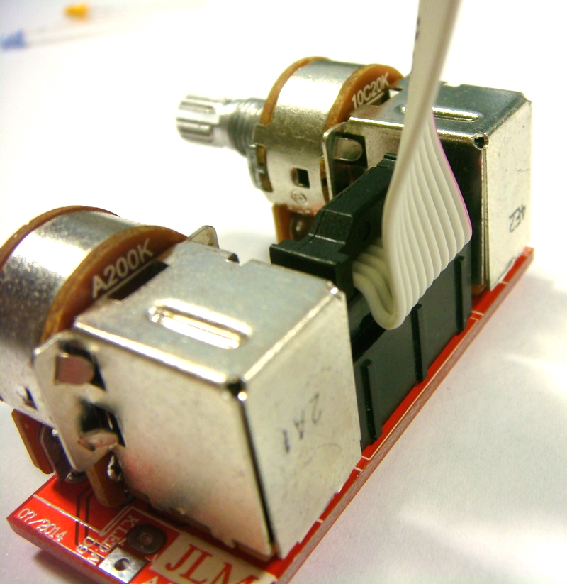
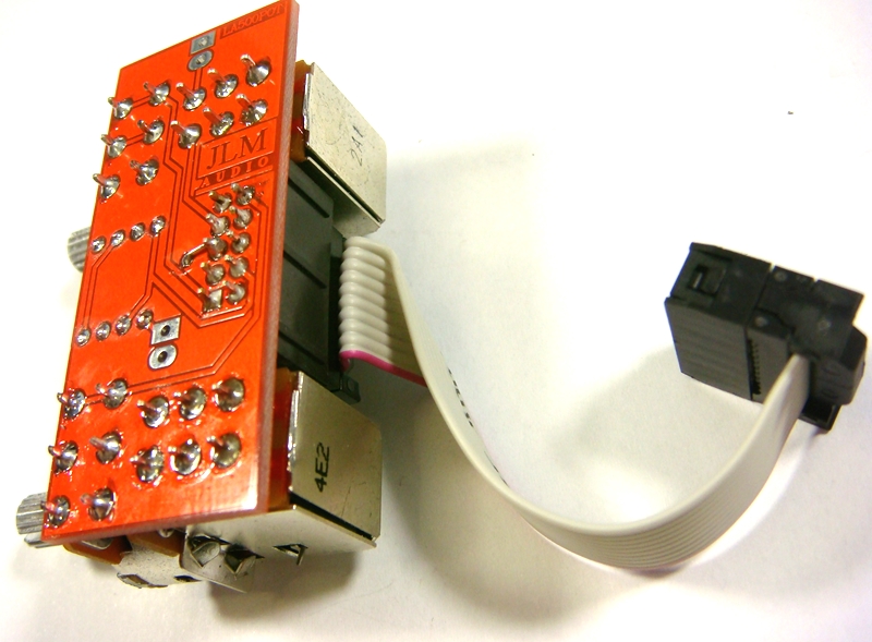
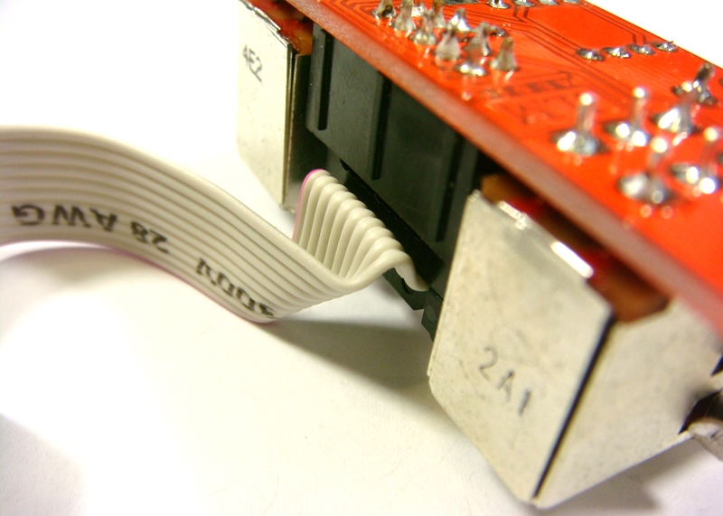
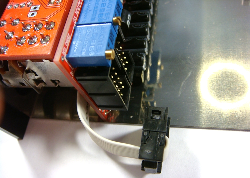
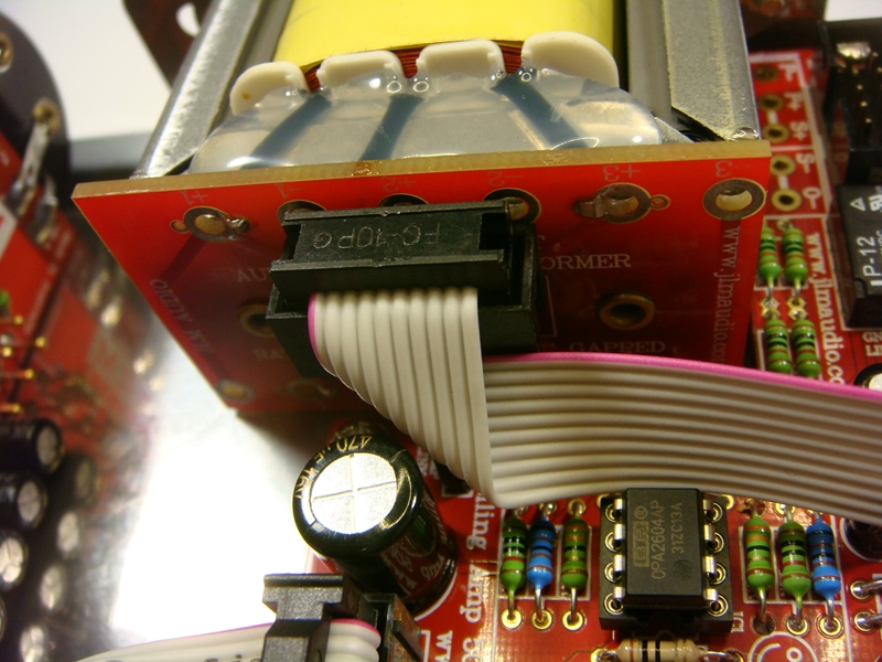
Fit and solder IDC headers in the POLARITY shown. Do not reverse. Triangle on header indicates pin 1 which is the square pad on the PCB.
The front opening in the IDC headers should both now be facing as shown below.
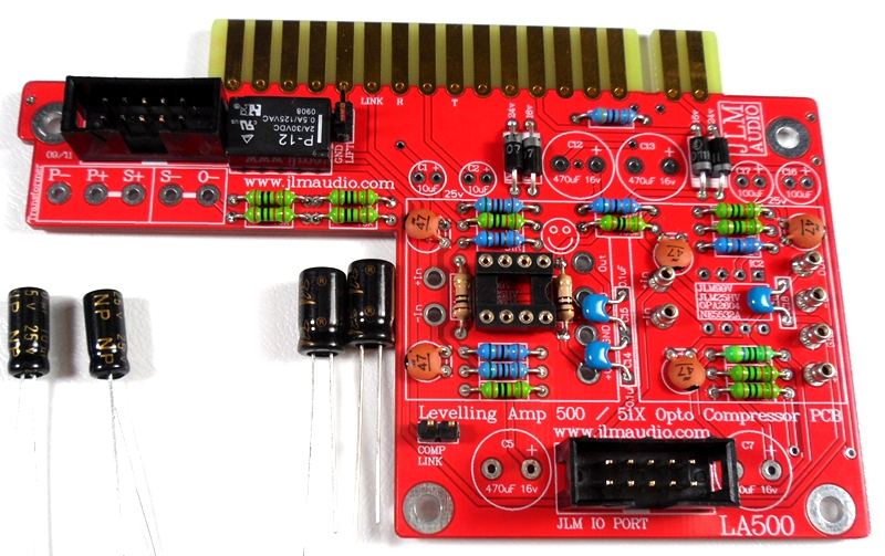
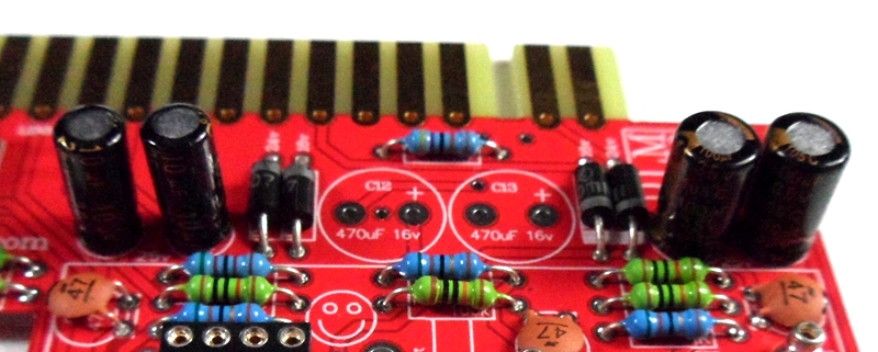
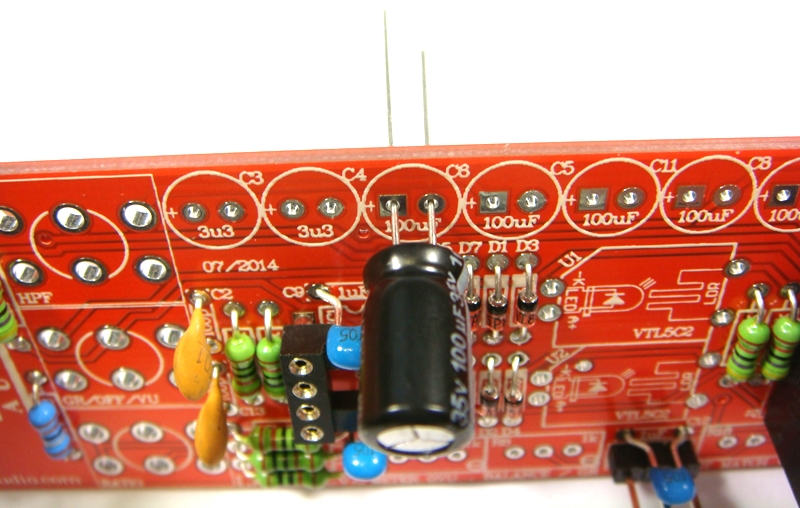
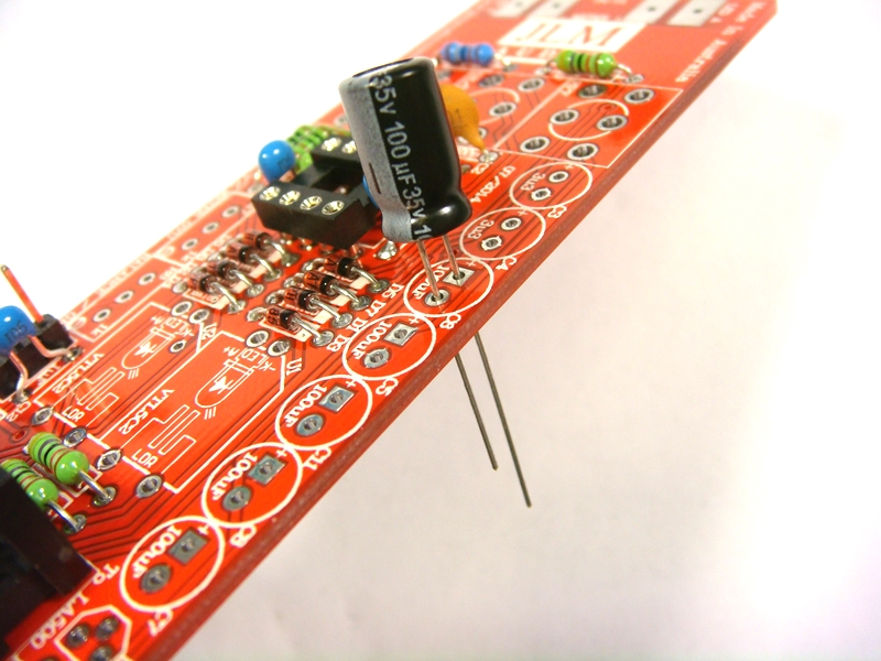
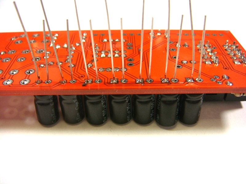
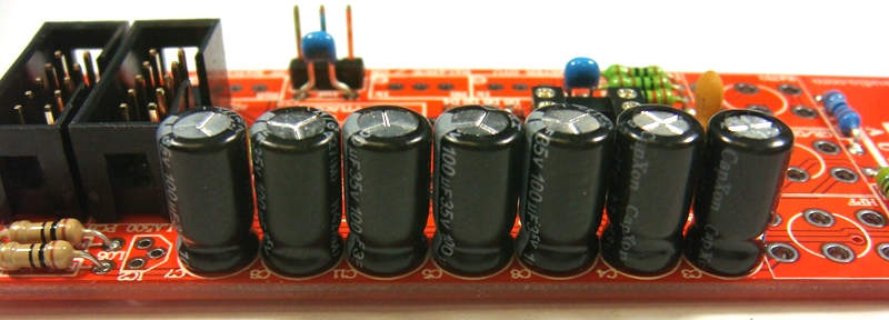
Fit and solder Electro caps to PCB. The 2 x 100uF caps are POLARIZED so must have there long positive leg fitted to + marked on PCB overlay.
2 x 10uF and 4 x 470uF caps are NON polar types so can go in either way around on the PCB.
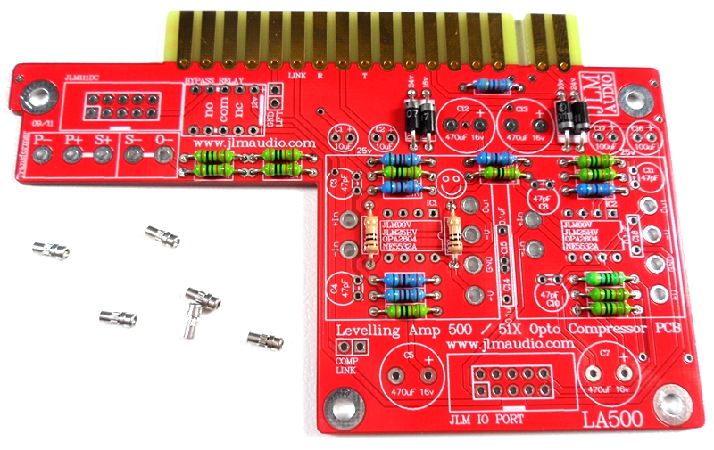
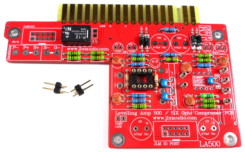
Fit 2 black jumper shunts to the 2 GND LIFT pins and the 2 COMP LINK pins
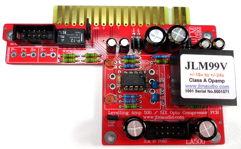
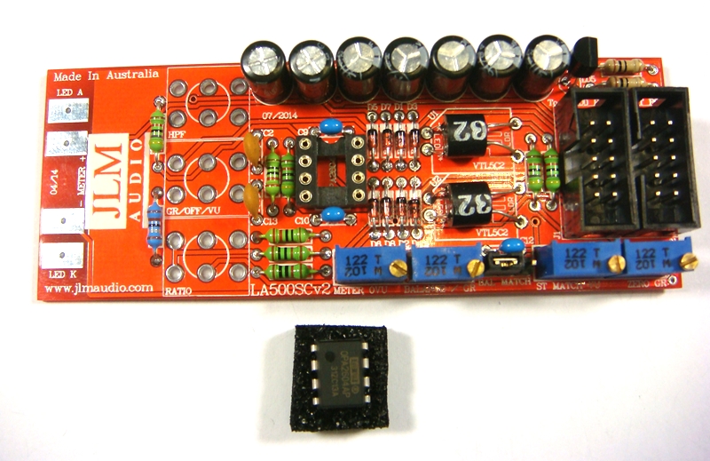
Fit NE5532A opamp in the correct POLARITY shown. 99v opamp can be fitted now or later. LA500 PCB is ready to go.
Put nuts and bolts etc back into zip lock bag the LA500 PCB kit came in to make sure they are not lost while you build the LA500SCv2 PCB next.
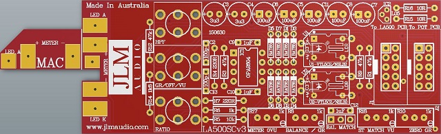
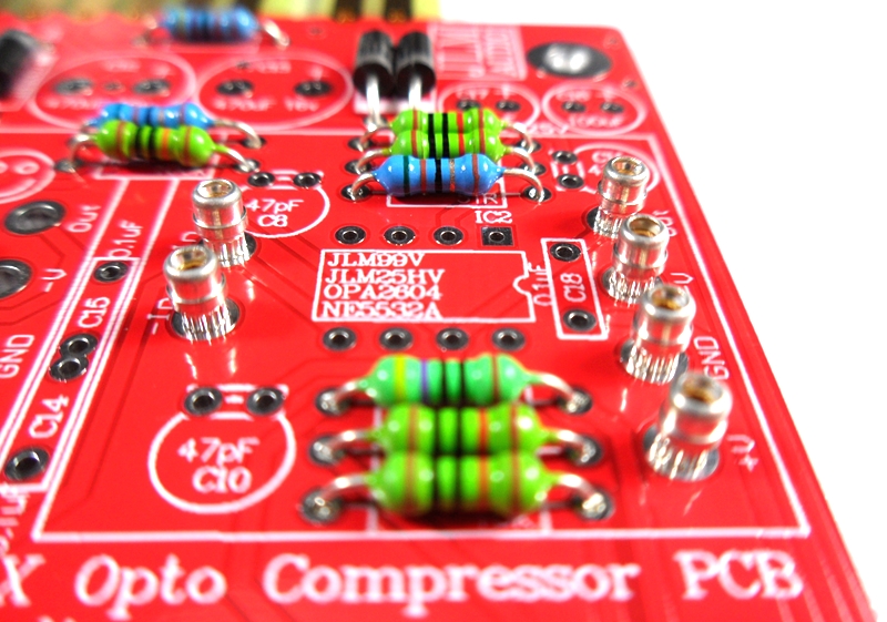
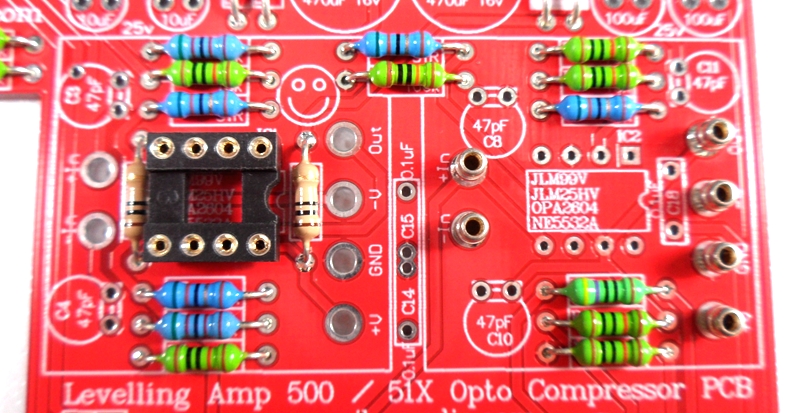
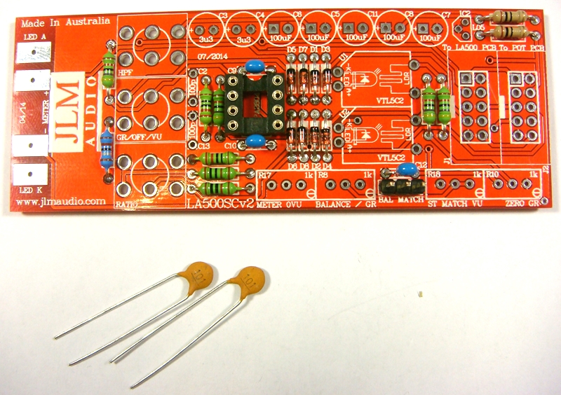
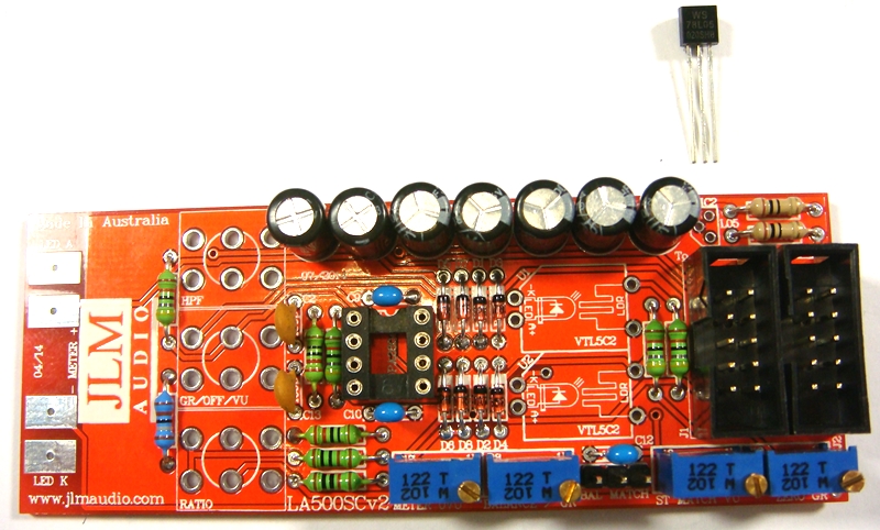
THE LA500SCv3 PCB is the MAC PCB but with no hand wiring and slow attack parts added
NEW LA500SCv3 PCB has some extra holes under U1 & U2 optos which can be used for opto as well
LA500SCv3 schematic at the link below is the same.
http://www.jlmaudio.com/LA500A/LA500SCv3/LA500SCv3%20Schematic.pdf
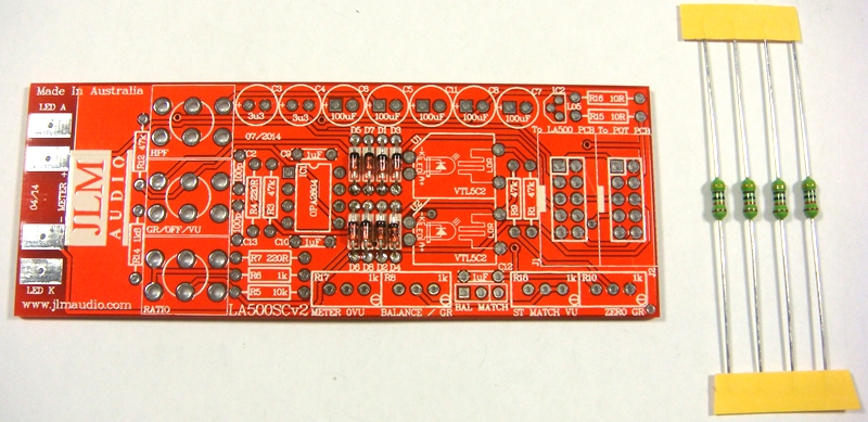
LA500SCv3 PCB parts kit
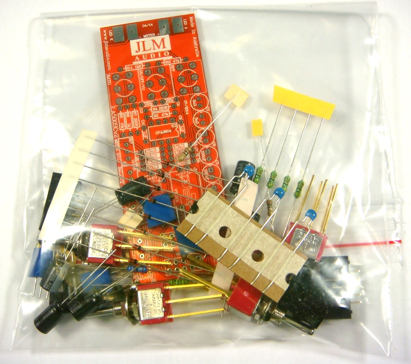
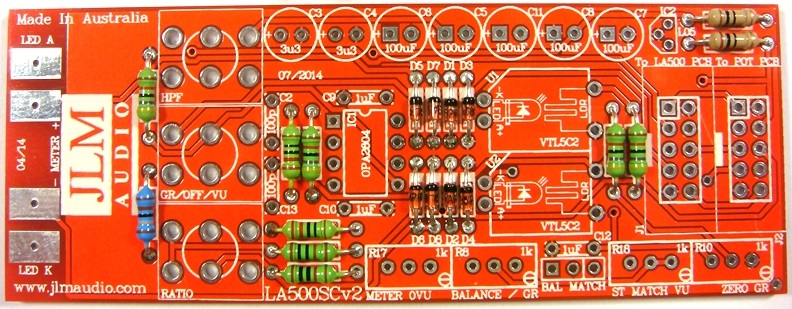
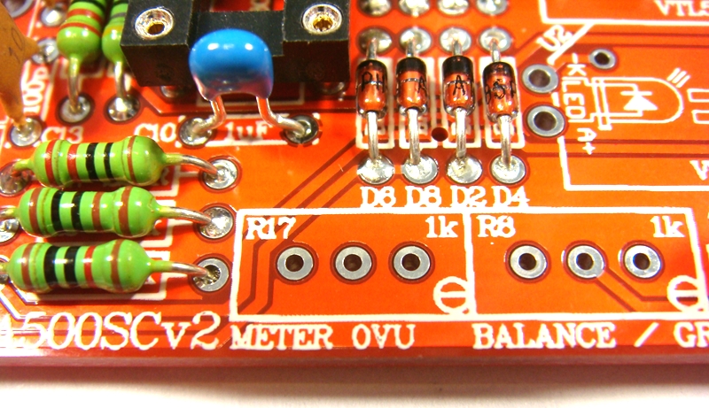
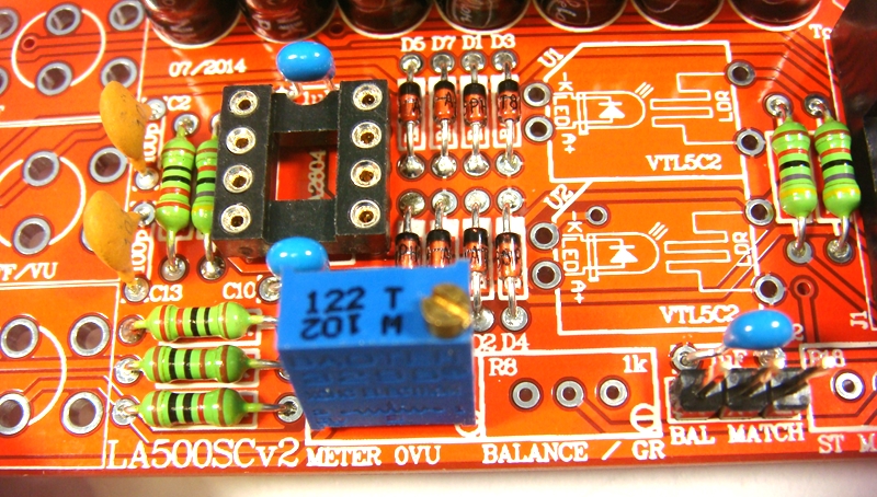
LA500SCv3 PCB. PCB overlay has all values and there are no options.
so PCB can be assembled directly from overlay.
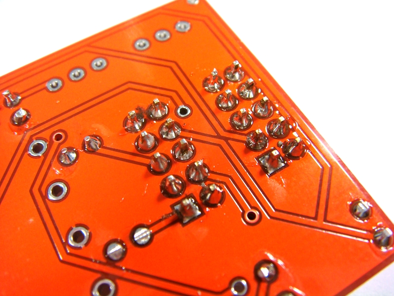
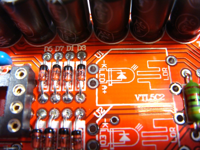
Fit all 8 x BAT85 diodes with there Cathode POLARIZED black stripe matching the white stripe on the MAC PCB overlay
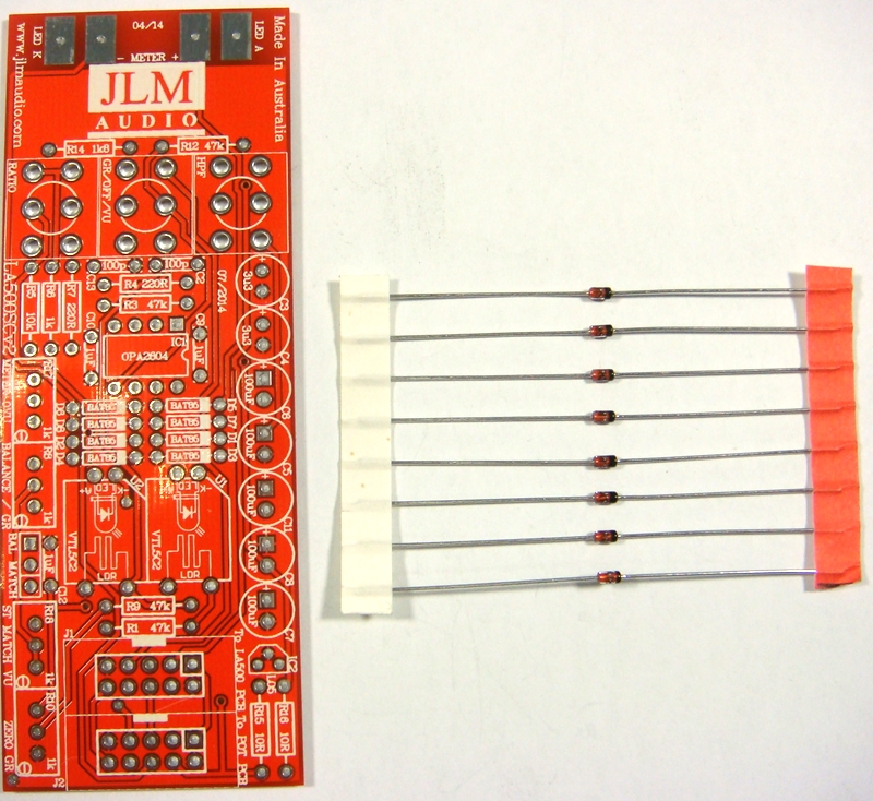

Solder all BAT85 diodes while holding PCB firmly upside down on flat surface. Make sure none of the center close pads are NOT shorted together.

Cut all diodes legs off at top of the solder joint and double check no solder joints missed soldering or are shorted together.
If you are not 100% with resistor colour codes use a multimeter to check values as you place the resistors
Fit all resistors at once bending the legs sightly outwards to hold them in place.
This helps to make sure no resistors are put in the wrong position.
Solder all resistors while holding PCB firmly upside down on flat surface.
Cut all resistor legs off at top of the solder joint and double check no solder joints missed soldering.
Fit and solder DIP8 socket in other opamp position. Make sure the POLARIZED socket matches the PCB overlay.
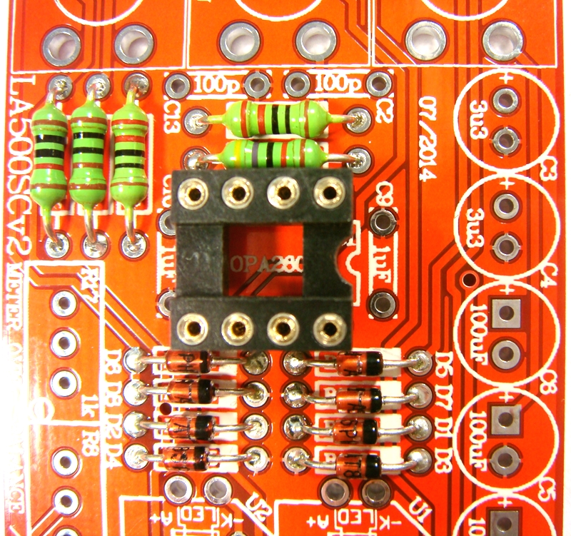
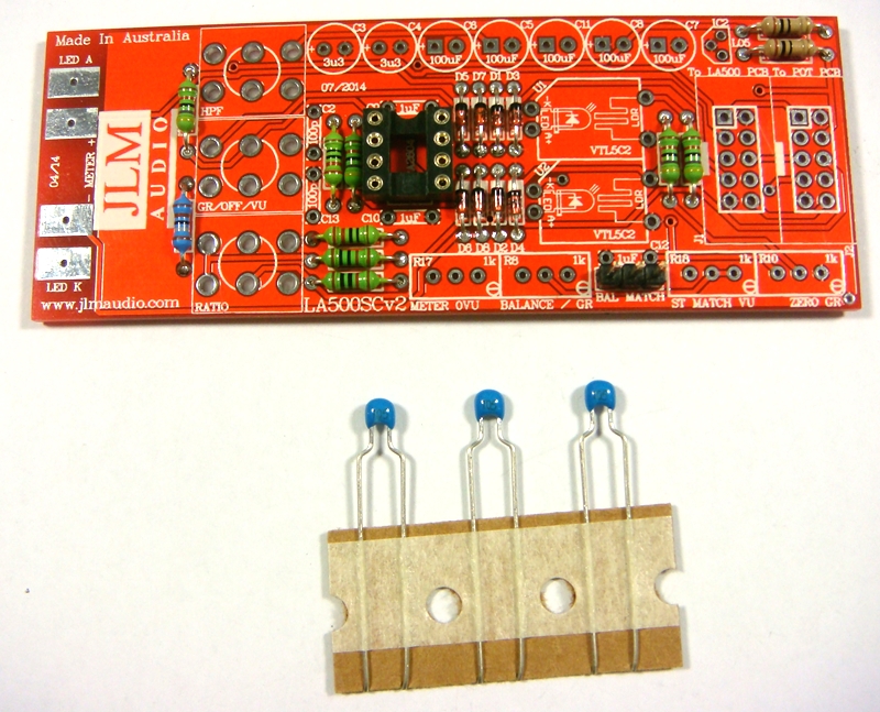
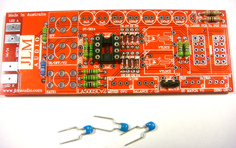
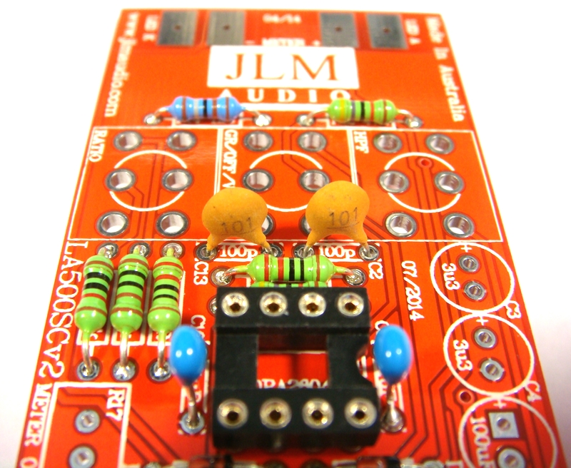
Fit and solder 3 x 1uF MONO caps in place.
Fit 2 x 100pF ceramic caps in place.
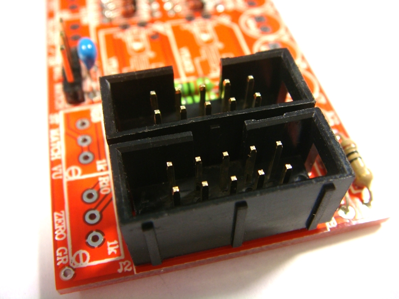
Fit and solder IDC headers in the POLARITY shown. Do not reverse. Triangle on header indicates pin 1 which is the square pad on the PCB.
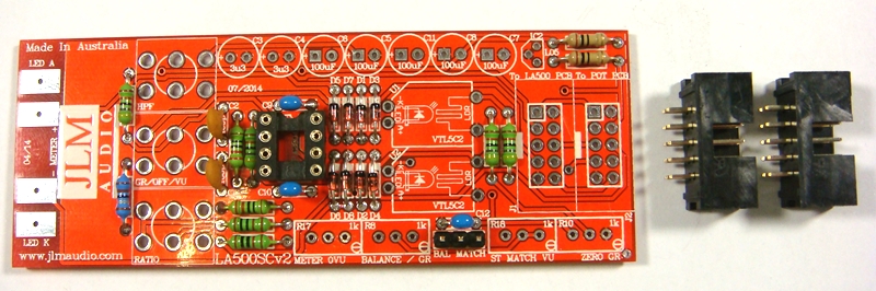
The front opening in the IDC headers should both now be facing as shown below.
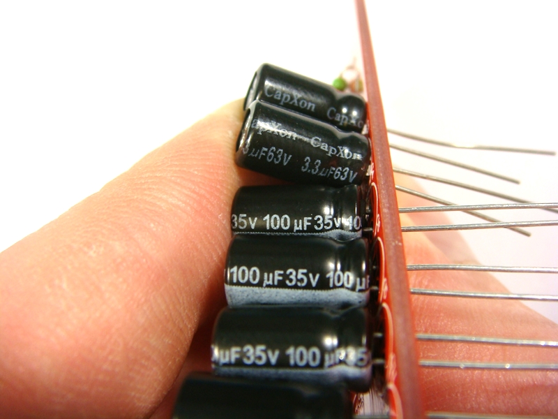
Fit and solder Electro caps to PCB. The 5 x 100uF caps are POLARIZED so must have there long positive leg fitted to + marked on PCB overlay.
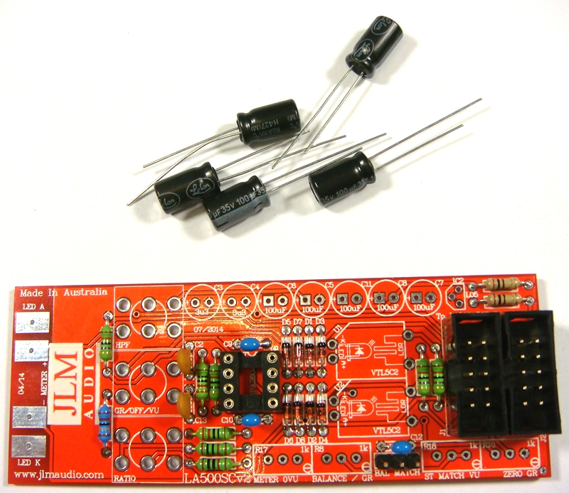
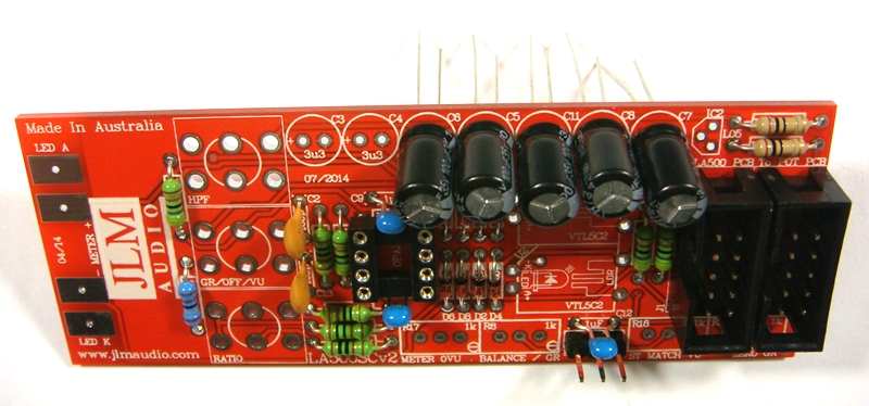
2 x 3.3uF acaps are NON polar types so can go in either way around on the PCB.
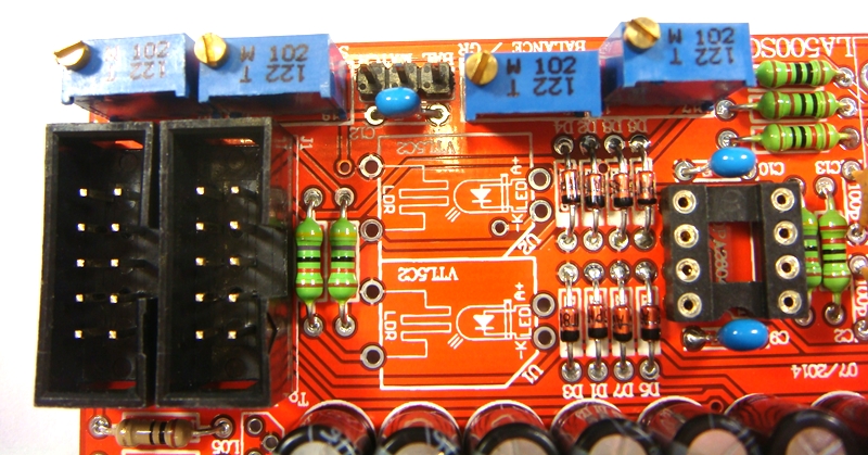
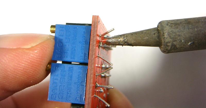
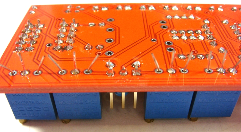
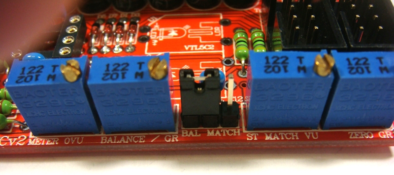
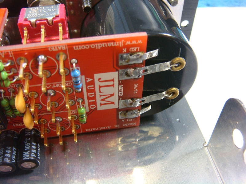
Fit and solder 4 trim pots as shown 1k = 102 code. Place pot so trim screw is in corner shown below
If you have received 103 trim pots please do not use them and contact us for replacements
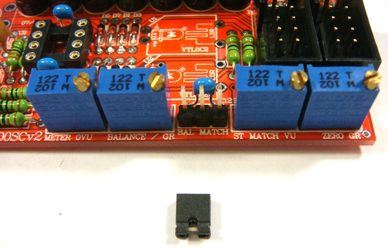
Fit and solder 3 pin header as shown below
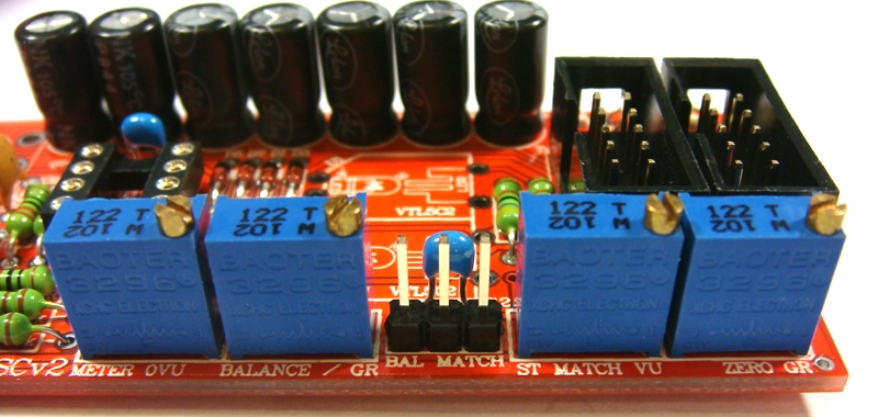
Fit shunt to the 2 pins to the left
Fit and solder 78L05 5v regulator as shown below
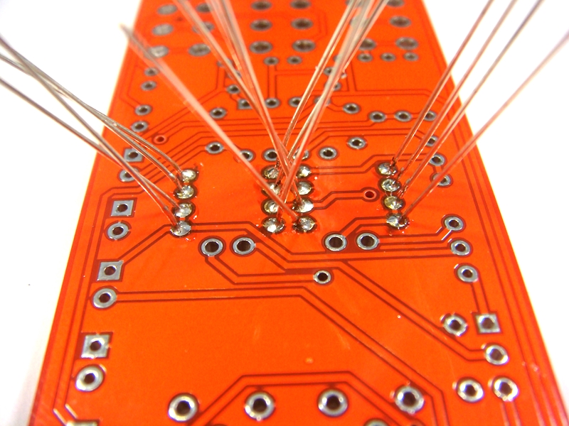
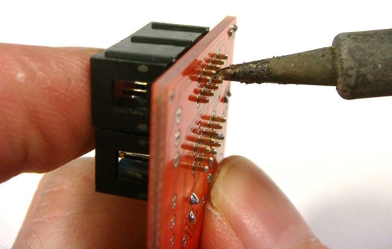
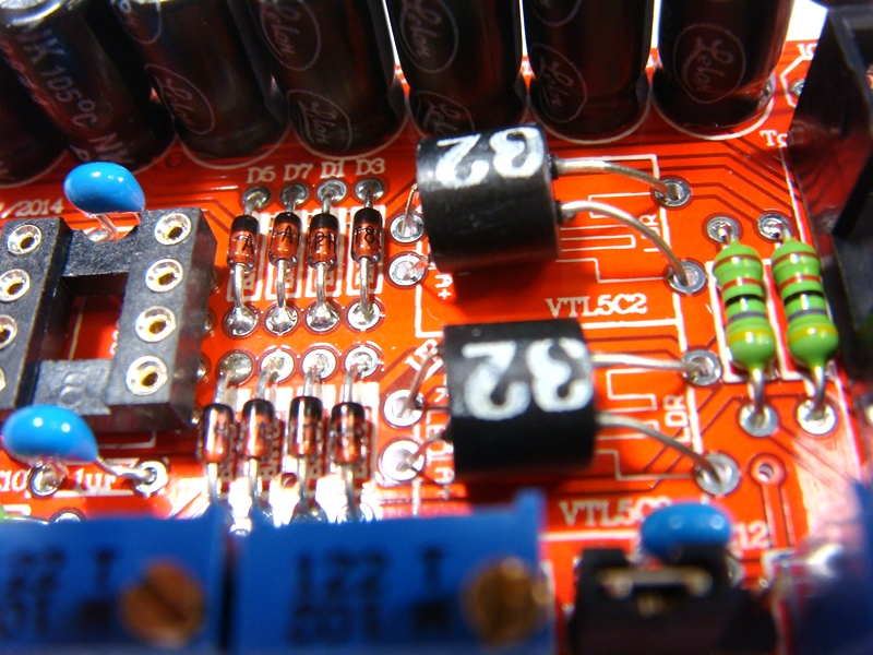
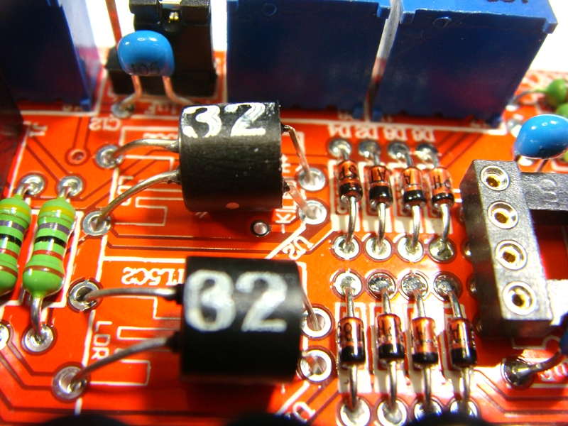
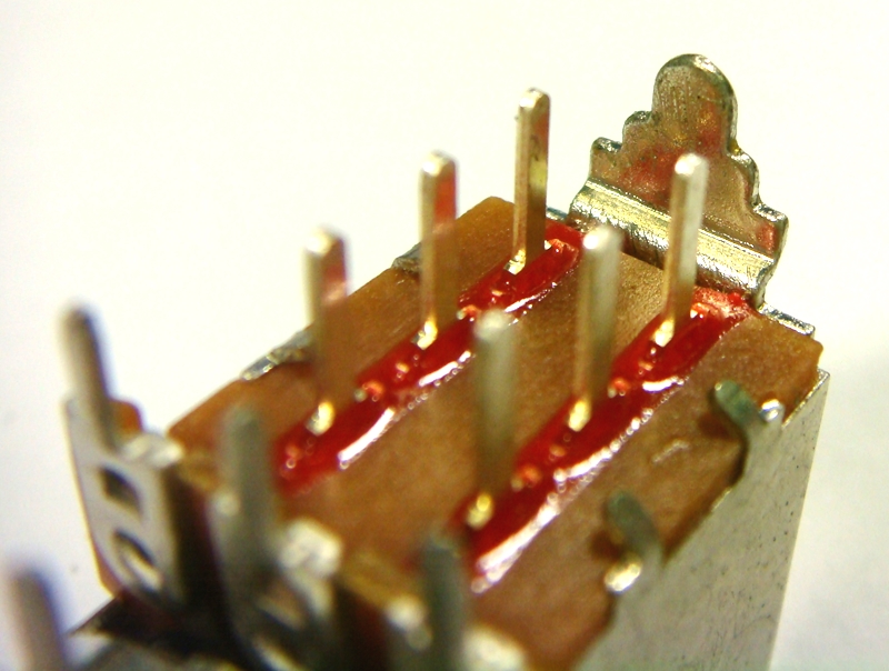
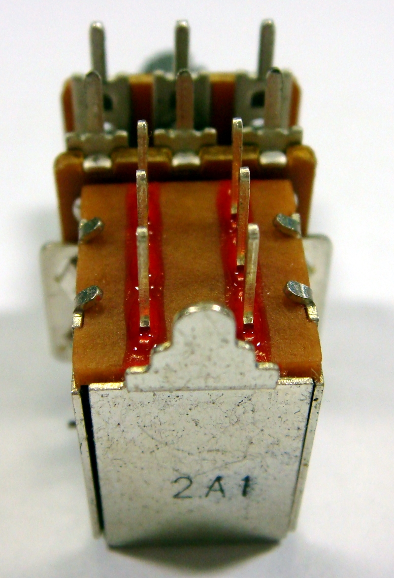
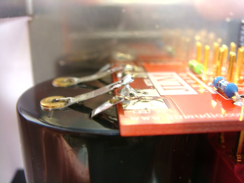
Fit and solder NSL32 optos as shown below. Short legs are LED & Long legs are LDR on NSL-32.
The NSL32 Cathode has a dot marked on the case which goes to -K. Be gentle with the wire legs on the opto when shaping them for the PCB.
Note: If you are building a stereo matched pair. Fit the 2 optos in the plastic bag marked U1 into the U1 position on each separate PCB and same for the bag with the U2 pair.
If building just one comp use the 2 optos in the bag and either opto can go into U1 or U2.
Plug in NE5532AP opamp the correct way around as shown below and put the built LA500SCv3 and the 3 switches left over back in the plastic bag and move on to the LA500POTv3 kit.
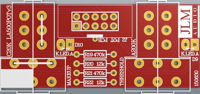
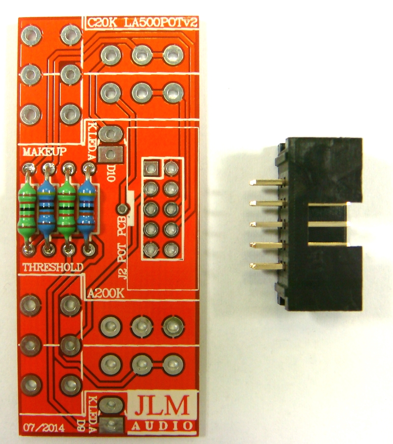
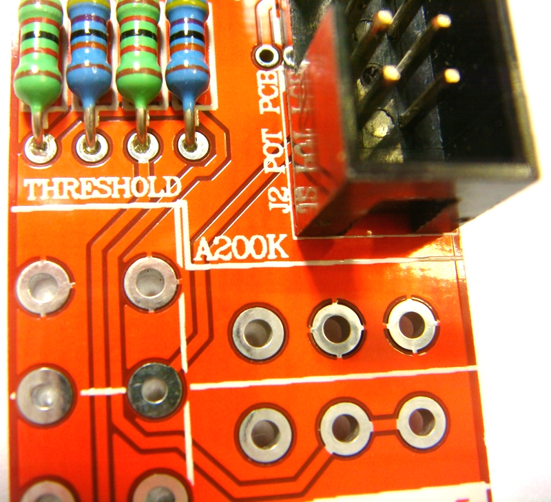
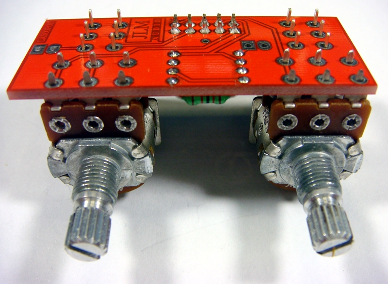
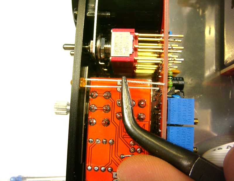
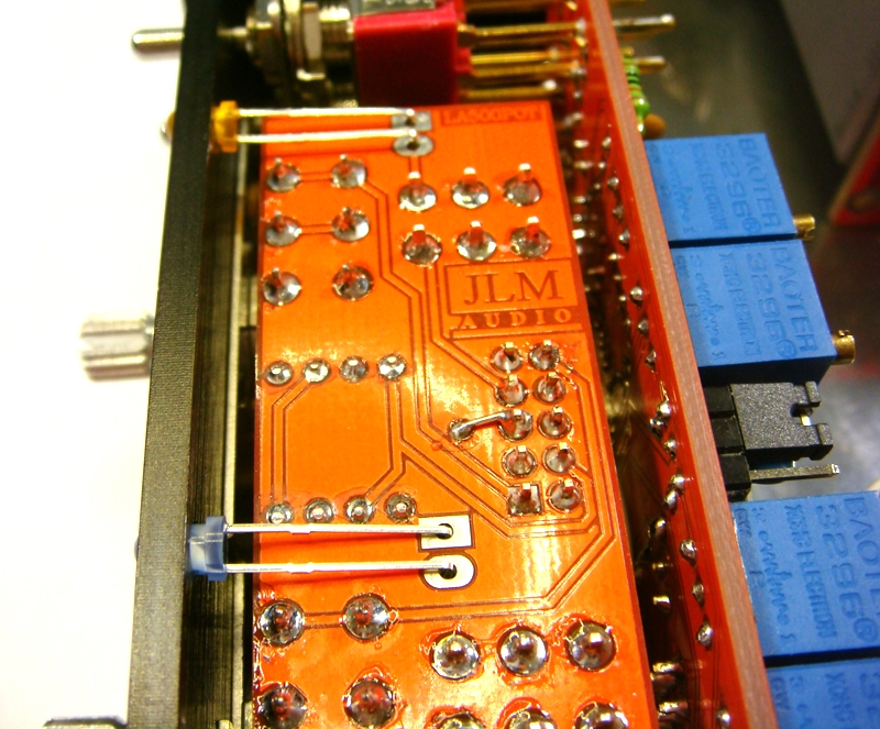
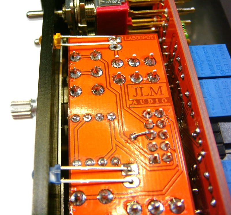
LA500POTv4 PCB holds the Threshold & Makeup pots with there pull switches for slow attack and stereo side chain linking as well as the new leds.
PCB overlay has all values and there are no options.
so PCB can be assembled directly from overlay.
LA500POTv4 schematic here

Fit all resistors at once bending the legs sightly outwards to hold them in place.
This helps to make sure no resistors are put in the wrong position.
NOTE All new kits have new blue led so now have 2 x 120k resistor instead of 2x 470k.


Fit and solder IDC headers in the POLARITY shown. Do not reverse. Triangle on header indicates pin 1 which is the square pad on the PCB.
The front opening in the IDC headers should now be facing as shown below.
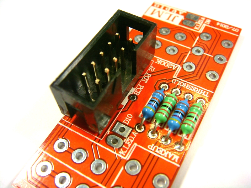
Solder one pin and check the connector is sitting flat against PCB. If not reheat while pressing on connector.
Solder all 10 pins and check none have any solder shorts when finished.
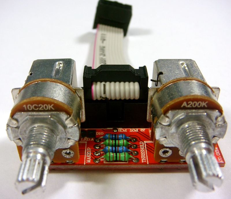
WARNING The 2 pots look the same but have very different values and curves so MUST GO IN THE CORRECT POSITIONS.
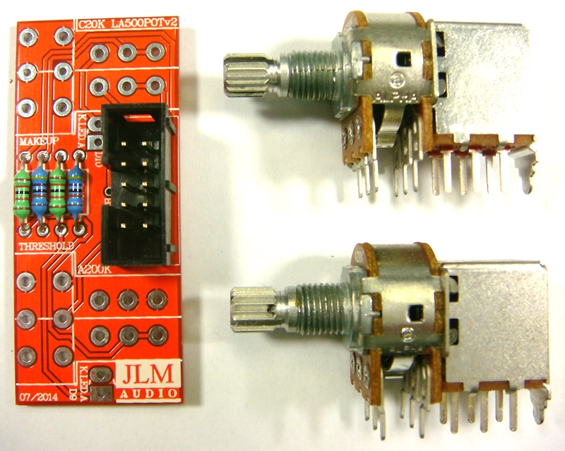
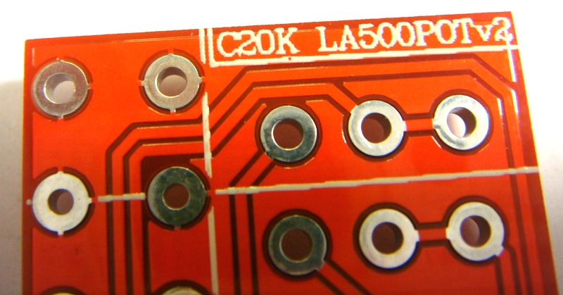
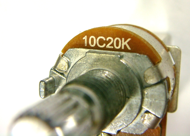
C20K dual 20k reverse log pot
A200K dual 200k log pot

Cut off locate tabs with cut cutters
You can also cut of the rear tags to leave a bit more room between the front 2 pcbs but it is not essential.

Solder one short leg on each pot to hold them in place.
Solder one pin and check the pot is sitting flat against PCB. If not reheat while pressing on pot until it is sitting correctly.

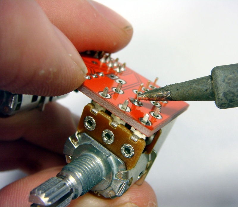
Solder all pot and switch legs and then check none have been missed.

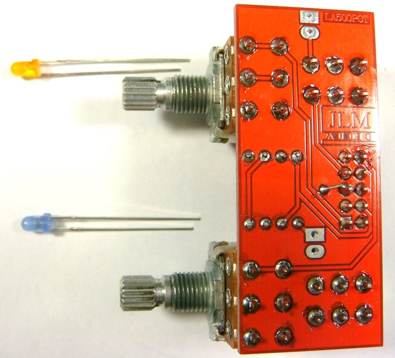
The 2 LEDs will NOT be fitted until later when the LA500POTv4 PCB is bolted to the bracket and front panel
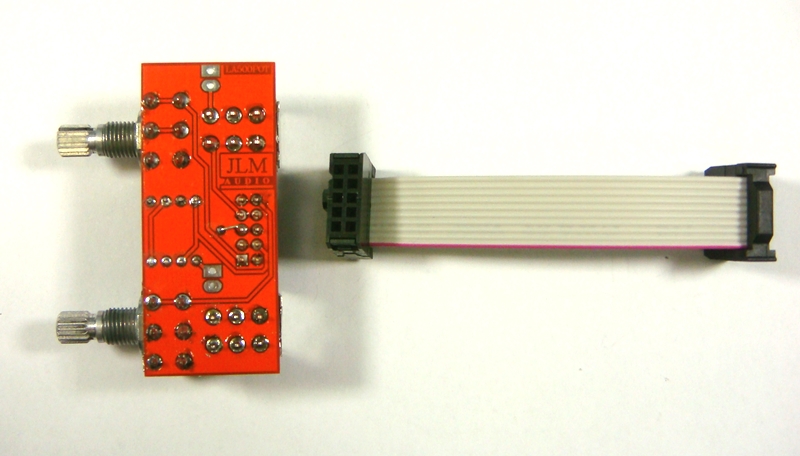
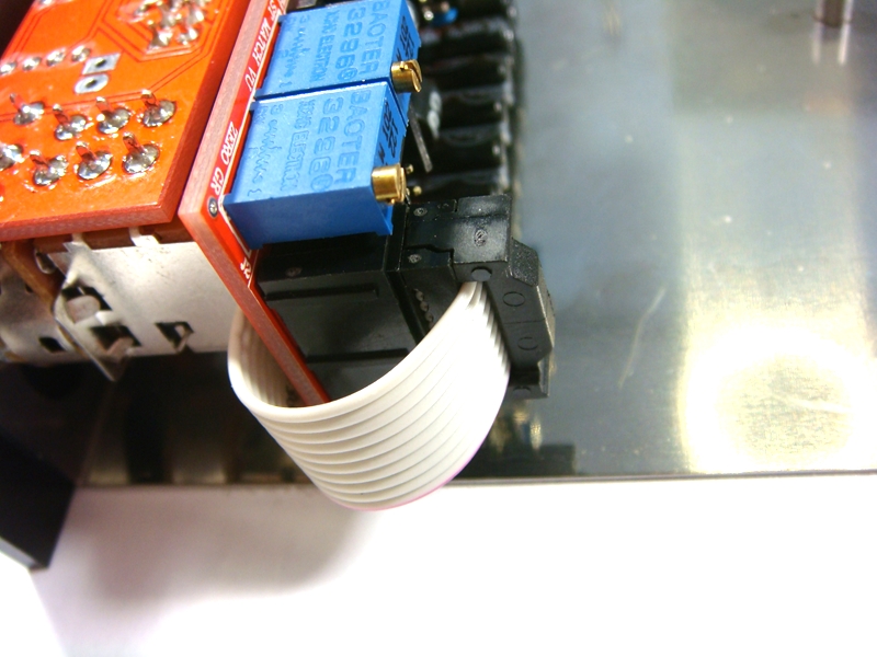
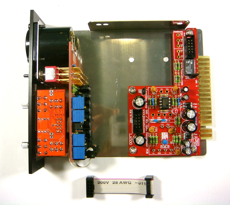
The ribbon cable can be plugged in and bent into shape and then we are ready to move on to final assembly of the LA500A.
Note if you have the wrong cable in the LA500POT kit click link below to fix it
http://www.jlmaudio.com/forum/viewtopic ... 2980#p2980
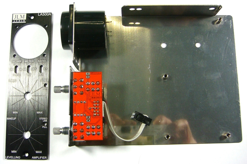
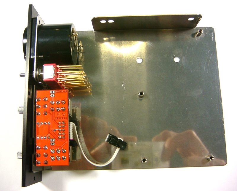
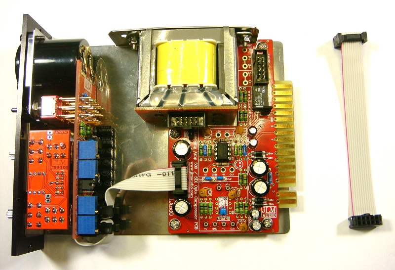
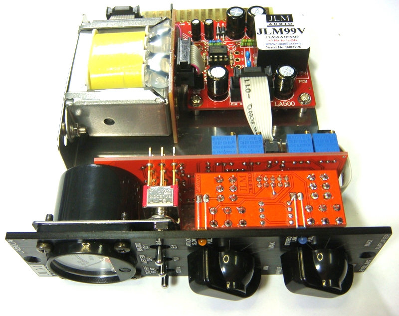
Final Assembly of LA500A
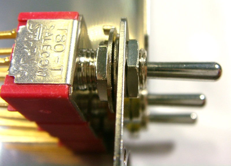
Wind the back nut fully down on to the 3 switches. Fit the flat washers on next.
Cut the sides of the middle flat washers with sudecutters so it does not overlap the other washers.
Fit the 3 shake proof washers on next.
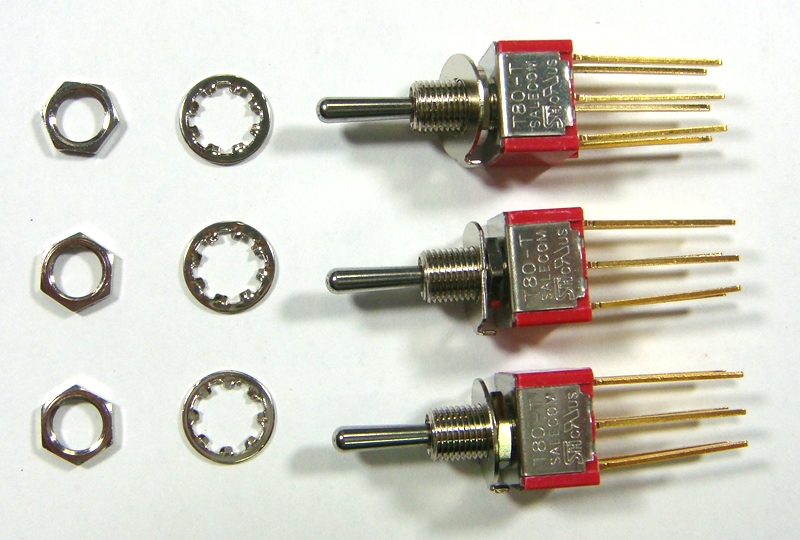
Fit nuts and hand tighten to check alignment.
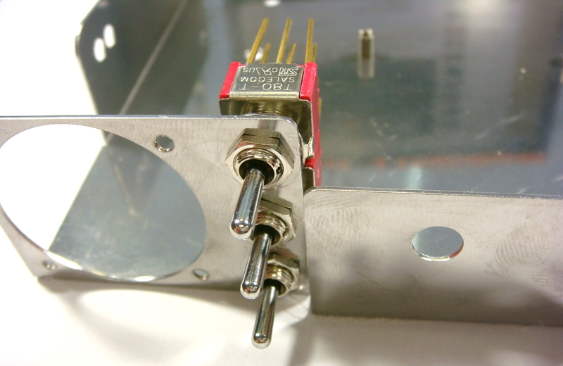
The threaded section of the 3 toggle should be level with the meter section of the stainless steel bracket.
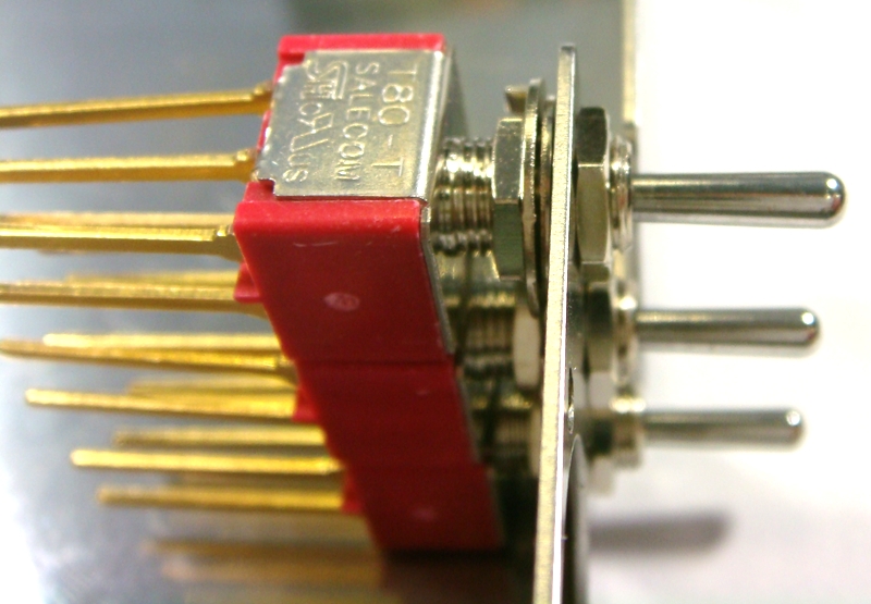
Adjust if needed before tightening the 3 nuts.
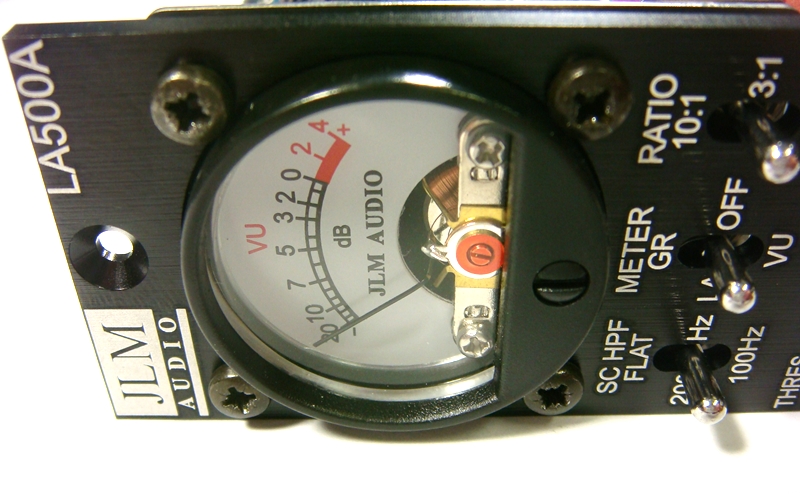
Fit Meter into the stainless steelbracket from the front.
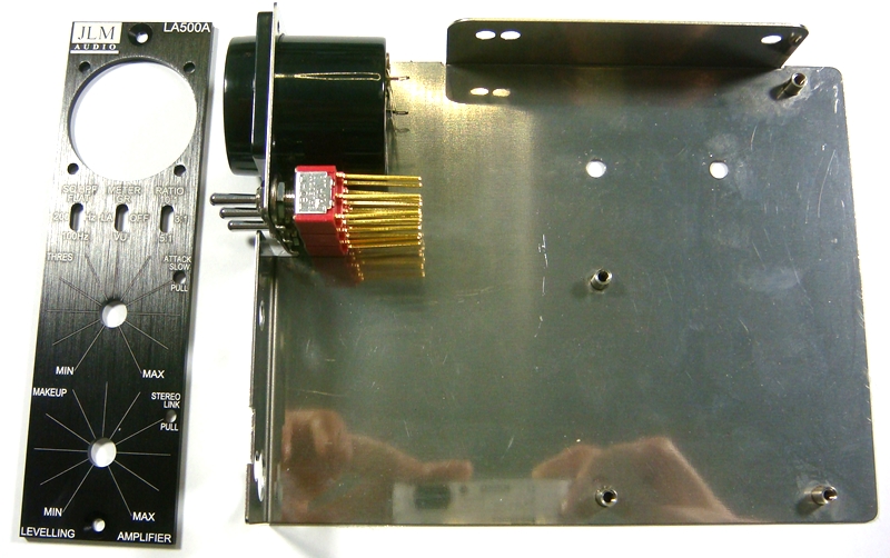
Fit front panel and fit 2 meter screws hand tight to hold assembly together.
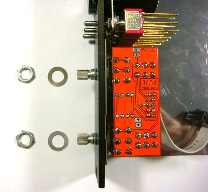
Fit LA500POTv2 PCB pots into bracket and front panel and do up pot nuts tight to hold assembly together.
Fit the rest of the meter bolts and tighten all 4 bolts gently. Do NOT over-tighten them or you may strip the bracket thread.
Lock-tight can be useful in a always travelling lunchbox to stop them shacking loose.
Bend up meter solder tabs so LA500SCv2 PCB can be slide directly onto the switch legs.
Hold down LA500SCv2 PCB flat against the meter so it is sitting parallel to the front panel and solder one leg of the top and bottom switches to hold in place.

Fold meter tabs down hard against the PCB and solder.
If the tabs spring up use a small screwdriver to hold them down while soldering.
Plug in ribbon cable from LA500POTv2 PCBand push any extra length back in between the 2 PCBs
If everything looks parallel and neat you can now solder all toggle switch legs with the LA500A face down.
Solder each row of 3 and cut the excess off so you can get to the next row under it.
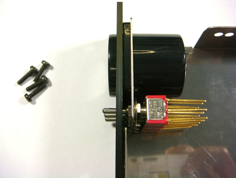
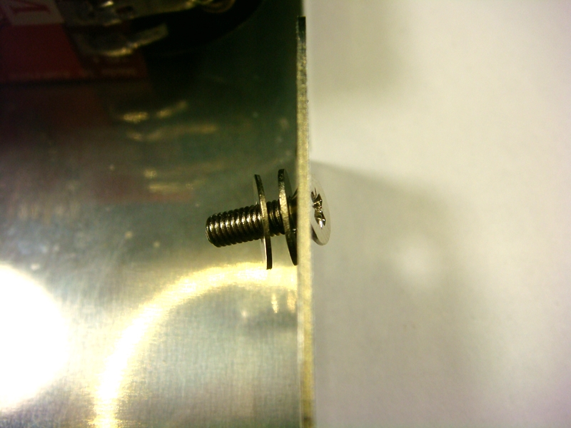
Fit the LA500 PCB to the 4 threaded stand offs with 4 x 3mm x 6mm bolts and lock washers.
Fit short ribbon cable between LA500SCv2 and LA500 PCB

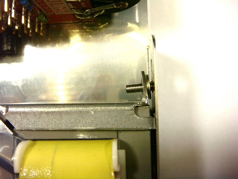
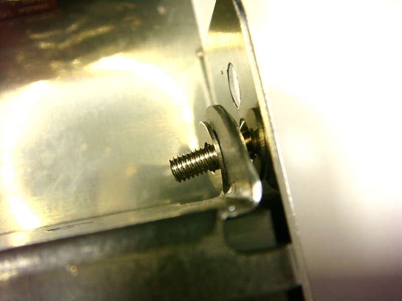
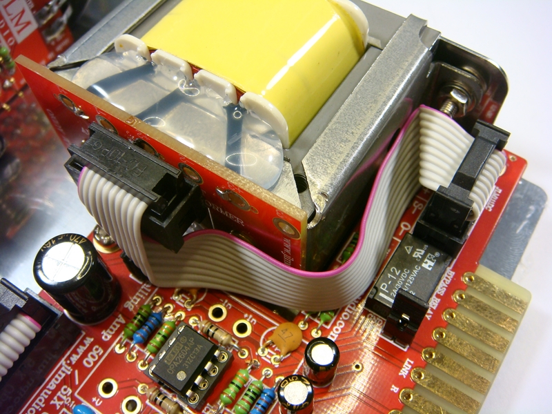
Fit transformer with hardware as shown below
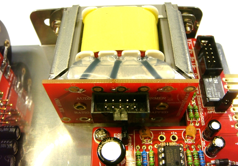
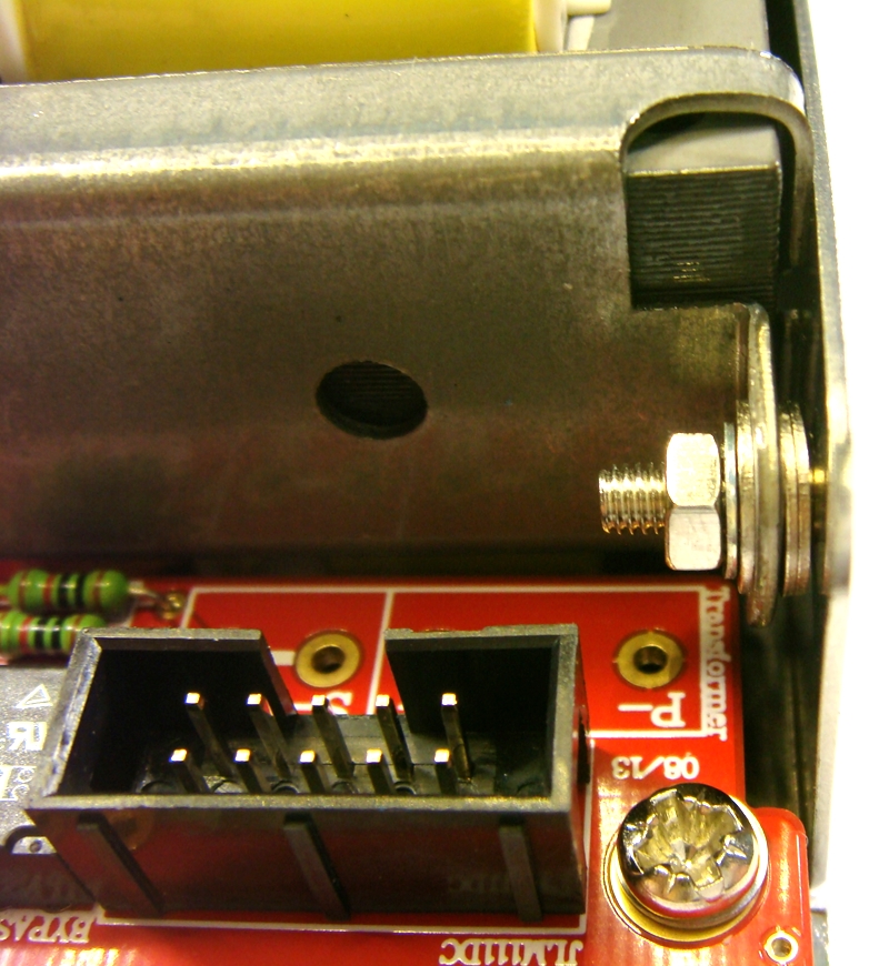
Fit ribbon cable as shown below. Make sure sure end without the cable lock on goes into the transformer socket.
Fit LEDs as shown below. Long LED leg goes to the square solder pad. Do NOT swap the colours as they will not be the correct brightness.
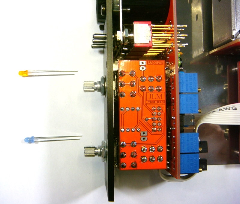
With LED held hard against the front panel grab both legs at the front edge of the PCB holes. Fold both legs at 90 degrees and trim folded part of leg to about 3 to 5mm long.

Solder LED legs to PCB.
Fit JLM99v on the the LA500A PCB
Make sure the pots are turn fully counterclock wise and fit knobs so the line up with MIN dial line.
Compressor setup procedure
1. Set LA to Threshold pot fully CCW, Makeup pot to CCW. Ratio switch to 3:1, Meter switch to VU, HPF switch to FLAT.
2. Apply 1kHz tone to LA500A input so you have the reference level of +4dBu (1.23vac) on the LA500A output between pin 2 & 3 of the XLR.
3. Or plug LA500A output into VU or PPM meter that is calibrated to 0VU = +4dBu. If voltage not correct adjust 1kHz generator level until correct.
4. Adjust meter 0VU trim pot for desired level for 0VU on the meter.
5. Switch Meter switch to GR and adjust Zero GR trim pot for 0VU on meter.
6. Turn up Threshold pot until you have 5dB of compression on meter.
7. Switch Meter switch between GR and VU and adjust Balance trim pot until the same reading is seen in both GR and VU.
8. Your ready to rock.
LA500A opto comp stereo matching mode.
1. Check Both LA500 comp alignments are correct.
2. With 1k tone of same level into both LA500 comps set 0VU on meter switched to VU and turn up Threshold pot to get -5dB on meter and switch to GR to check you have -5dB showing on both meters.
3. Link the comps. If meters move away from each other by more than a +/-1dB move jumper to MATCH end on the compressor which shows more gain reduction on the meter.
NOTE: If comps are very different when linked due to be ordered at different times or batches it is best to swap U1 from one comp with U2 of the other and realign before resorting to stereo match mode. If comps were bought together we will have labelled the opto bags with a U1 and U2 which are already matched pairs
Original balance trim pot will now adjust GR meter level when switched to GR (U2 audio opto) and new ST Match trim pot R18 will adjust VU meter level when switched to VU (U1 meter opto)
Image
1. Setup both comp with 1k tone and set 0VU on meter switched to VU and turn up Threshold pot to get -5dB on meter.
2. Turn threshold pot off on modified comp (fully CCW)
3. Link the comps. Adjust modified VU trim pot until both comps show the same VU meter readings.
4. Switch both comps to GR and adjust modified comp new GR pot until both comps show same GR meter readings.
5. Your comps should be matched.
To check match
1. With 1k tone of same level into both LA500 comps set 0VU on meter switched to VU and turn up Threshold pot to get -5dB on meter and switch to GR to check you have -5dB showing on both meters.
2. Link the comps. If meters move away from each other by more than a +/-0.5dB trim modified comps New GR & New VU trim pot until perfect match when linked.
LA500A opto comp fault finding.
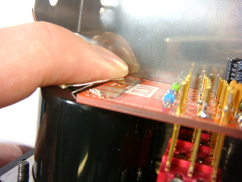
Comp permanently stuck in hard bypass. Then check the meter led lights when switching to GR or VU? If you have a open circuit led in the meter the bypass relay will never operate to lift the hard bypass so you will never hear the comp.
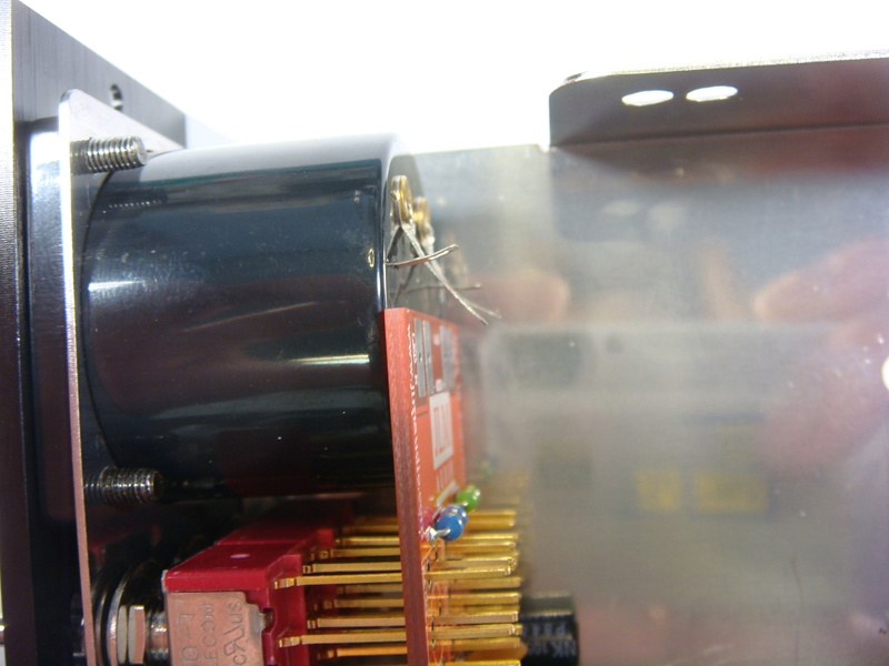
You can add a wire link across the outside meter terminals to see if your hard bypass relay now works.
Check you have +15 to 16v (+19 to 20v 51X) at pin 8 of both NE5532A. Check you have -15v to 16v (-19 to 20v 51X) at pin 4 of both NE5532A.
All other pins of NE5532A on BIO500/LA500 main pcb should be close to 0v. Place black lead from your meter on 0v for all voltage measurement.
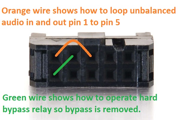
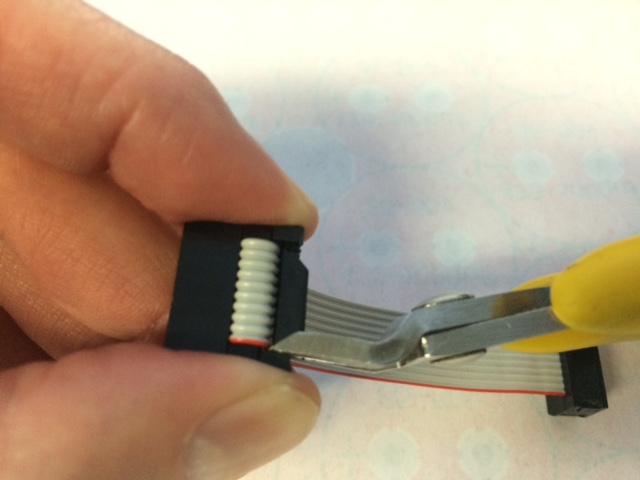
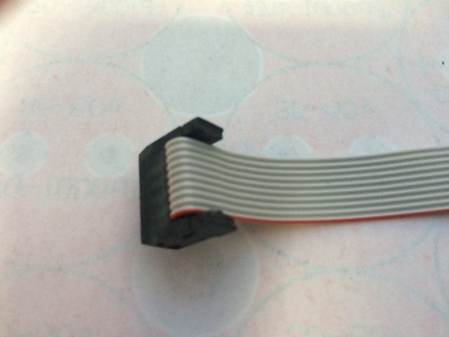
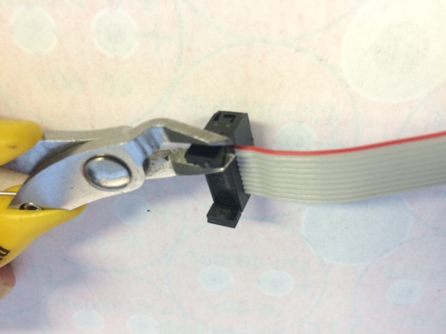
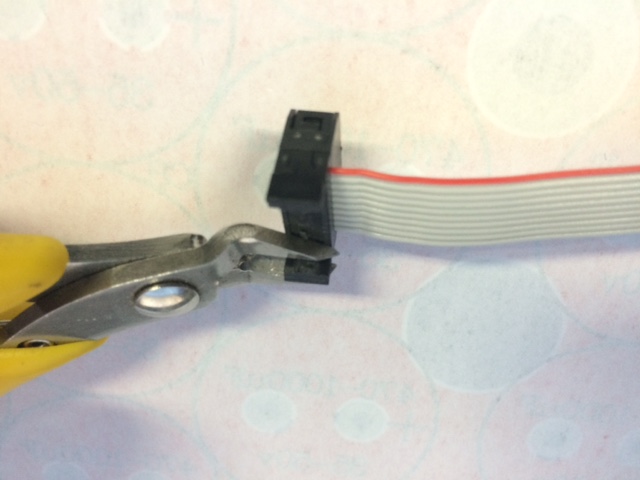
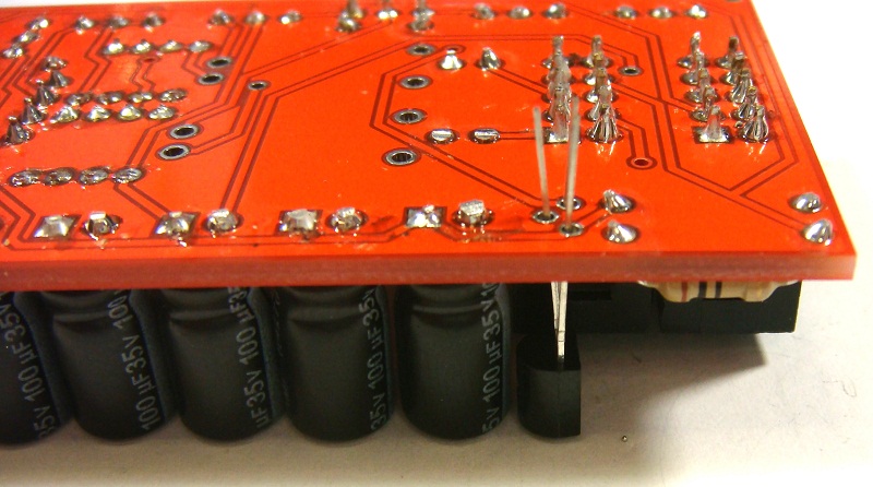
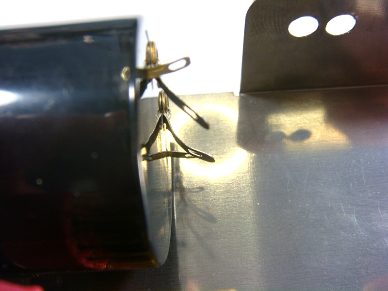
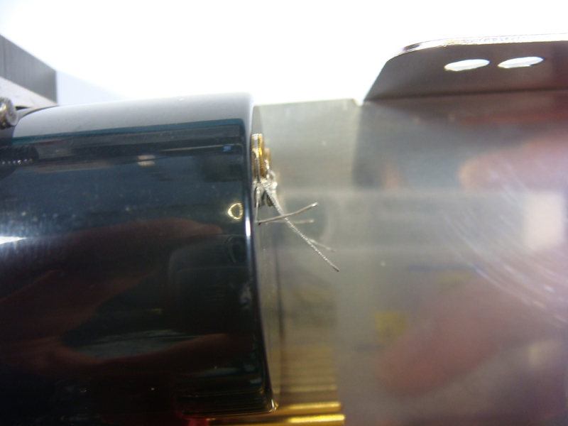
Test BIO500/LA500 main pcb by itself by unplugging BIO500/LA500 main pcb ribbon cable from LA500SC pcb and fitting two cut off component leg loops as shown below.
You should have a unity gain audio loop if BIO500/LA500 main pcb is working. This test proves BIO500/LA500 main PCB and output transformer are both working.
You can plug the relay green wire loop in and out to switch between bypass and BIO500 audio path to check audio level is correct.