The four most significant differences between the DInGo and the PUP are that the PUP -
(1) has no VCA
(2) has no capacity for the 99V/Hybrid/550c type discrete opamps
(3) has no onboard relay for hard-bypass of the external signal loop and
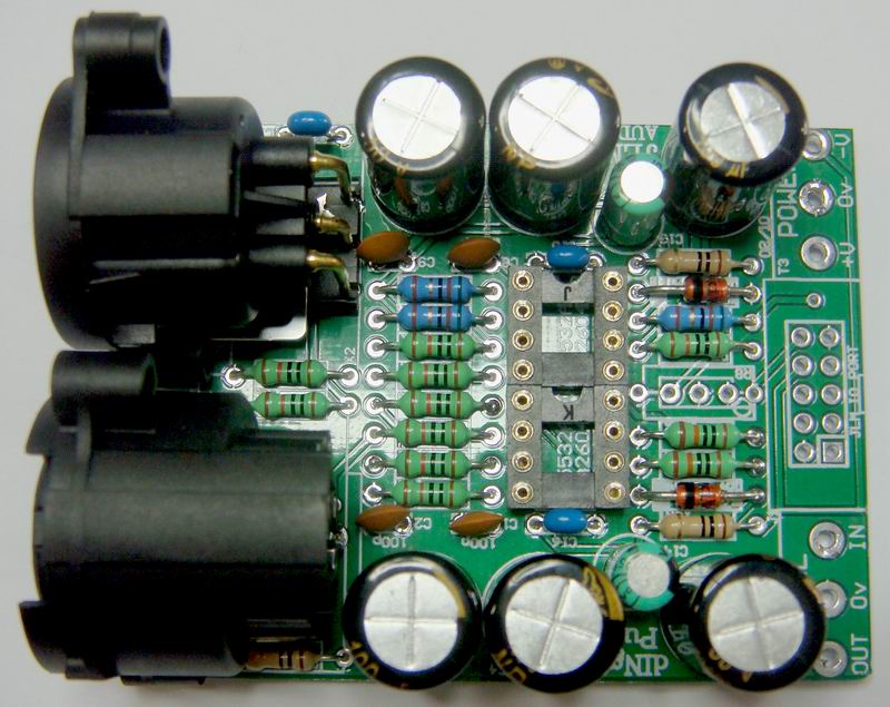
(4) uses the opamps to electrically balance and isolate the signal with a 6db gain, effectively eliminating the technical need for a transformer.
The sonic difference (and I'm guessing here) would be that the PUP is very neutral and that's how it is. The DInGo would allow more sonic variation for "character" by using the discrete opamps - it could be built to be anything from transparent to sticky goo.
BOTH the DInGo and PUP replace transformer in/outs, and while you can add a transformer to the DInGo, you do not need to do so. You would add one perhaps for the added 6db gain of a 1:2 output tranny when using the 99V type of opamp in the output socket.
We're all waiting for the EQ kit, but I'm sort of scared - I built my own version of a 1073 type EQ (LF bell, MF bell, HF and HPF shelf) and I just know it will sound crap compared to Joe's. I don't want to know