
What to run the most BA BAD BAN mic pres on the smallest MEPS SMPS power supply please read the Notes and Errata further down this page[/size]
NEW BLACK BA Ver2 PCB
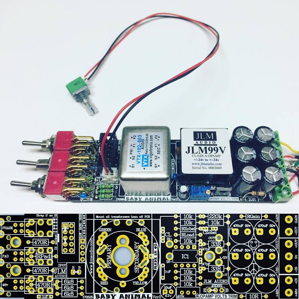
Complete circuit of JLM Baby Animal Ver2 Black PCB here
Note: Build same as old BA PCB except Zpot now has its own 2 pin connector connector and series resistor for Zpot is fitted to Rload on black pcb.
If fixed Z then wire link over 2 pin connector solder pads.
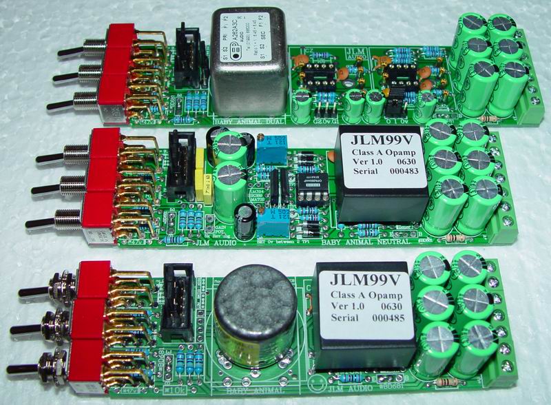
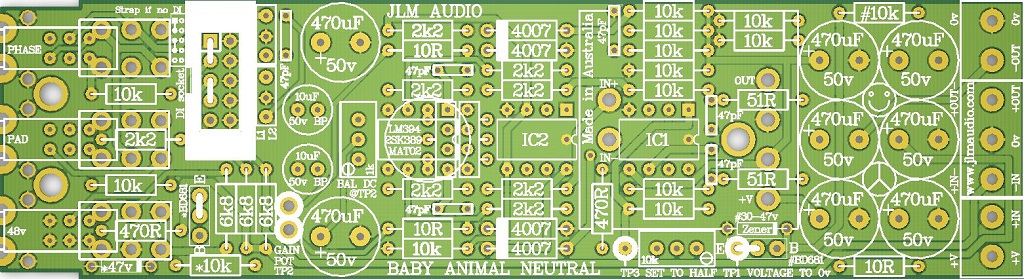
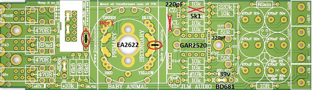
BA PCB
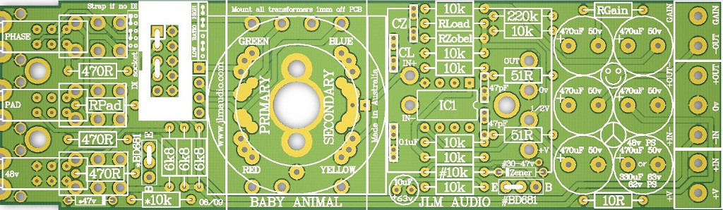
Complete circuit of JLM Baby Animal PCB here
Circuit for Baby Animal Mic Pre with JLM14 & OPA2604 here
Circuit for Baby Animal Mic Pre with JLM14 & JLM99v or Hybrid here
BAD PCB
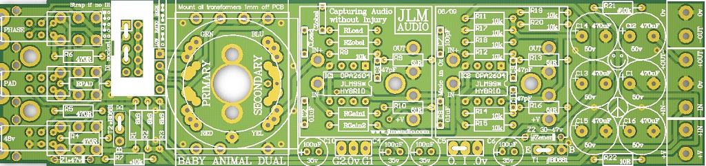
Complete circuit of JLM Baby Animal Dual PCB here
BAN PCB
See BAN build thread here
The BA & BAD PCB are easy to assemble with all parts with there value marked on the PCB needing to be fitted. Parts marked with * or # and zener diodes are only needed if running on higher than 48v or running opamps that need less then the +/-24v to run on. Parts with a name like Rload, CLoad, Rzobel, CZobel, RPad, RGain need to be selected to match the input transformer and opamp used. Their values for projects like the Dual99v can be found on the overlay sheet for the project.
Original 48 page BA thread on GroupDIY
https://groupdiy.com/index.php?topic=15245.0
Condensed version of The Lab Thread on JLM forum
http://www.jlmaudio.com/forum/viewtopic.php?f=2&t=11
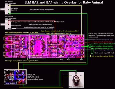
BA, BA2, BA4 Overlay wiring PDF Large PDF copy here
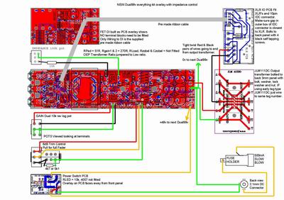
Dual99v, BAD Overlay wiring PDF Larger PDF copy here
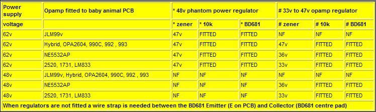
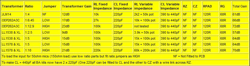
BA BAD BAN voltage settings
BA Settings (Ratios higher than 1:6.45 below not recommended unless using 50ohm microphones)
Building API 512, API 312 type mic pre on BA PCB
If using JLM25HV or JLM25HV FET NO BD681 is needed & 33v - 39v zener as they can run direct on the +/-24v of the BA PCB.
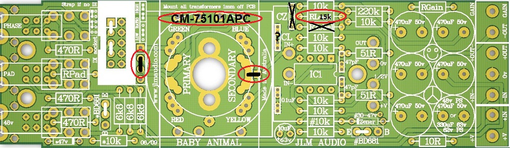
Cinemag CM-75101APC on BA PCB
Notes & Errata
Note 1. The New 48v 520mA 25w MEPS SMPS external & 48v 315mA 15w internal SMPS power supplies under high capacitive and dc current power up surge can go into hiccup protection mode (power light will flick on and off) more easily than the old non MEPS ones so the below soft start mod is recommended for all new BA BAD BAN builds.
DO NOT DO THIS SOFT START MOD TO ANY NEW BUILDS. If building 3 or more BA kits use our 48v 40W SMPS instead as it can run 8 BA BAD or BAN easy
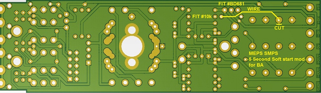
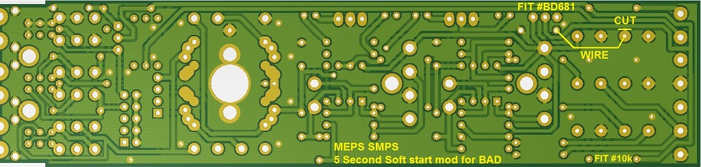
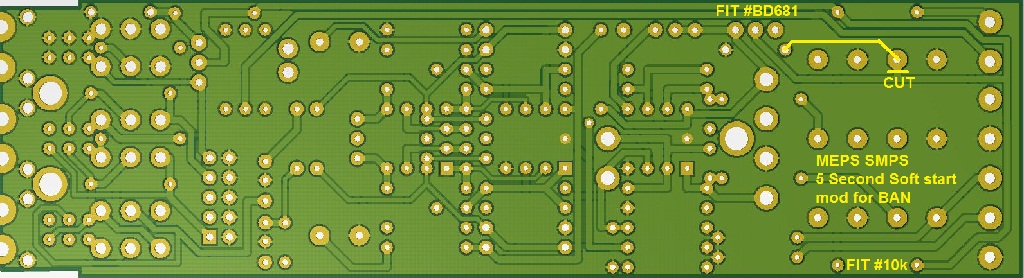
1. Do the soft start mod shown below. This leaves all parts fitted as normal but one track is cut and wire link added with #BD681 and #10k fitted. This gives 5 second soft start with no direct capacitance across the 48v SMPS and allows for the maximum possible BA BAD BAN combinations on one SMPS power supply. (#Zener is only needed as usual if opamp needs lower than 48v (+/-24v) rail.)
2. As always test each BA BAD BAN module on the 48v power one at a time without opamp fitted and test voltages and then with opamp fitted and test voltages to make sure the module is working properly. If one BA BAD BAN module puts the supply into hiccup mode there is a real fault.
3. While testing measure the voltage across the 10R resistor to see what current the BA BAD BAN module is drawing at idle (mA = V/10). Add up the total mA to check it is less than about 2/3rds of the specified current of the SMPS you are using to leave some headroom fro driving 600ohm loads.
4. Once all BA BAD BAN modules are tested to work correctly turn off and connect all the modules and power supply should powerup smoothly. If you are having problems email me with your exact configuration and which power supply you are using.
(Without mod each BA has 470uF and BAD abd BAN have 1000uF capacitance direct across the 48v rail which causes a short circuit for to long for the new MEPS SMPS)
BA MEPS SMPS Soft start mod (DO NOT DO THIS SOFT START MOD TO ANY NEW BUILDS. If building 3 or more BA kits use our 48v 40W SMPS instead as it can run 8 BA easy)
BAD MEPS SMPS Soft start mod (DO NOT DO THIS SOFT START MOD TO ANY NEW BUILDS. If building 3 or more BAD kits use our 48v 40W SMPS instead as it can run 8 BAD easy)
BAN MEPS SMPS Soft start mod (DO NOT DO THIS SOFT START MOD TO ANY NEW BUILDS. If building 3 or more BAN kits use our 48v 40W SMPS instead as it can run 8 BAN easy)
Some helpful photo's (If there is some detail you need a photo off let me know and I will add it here)
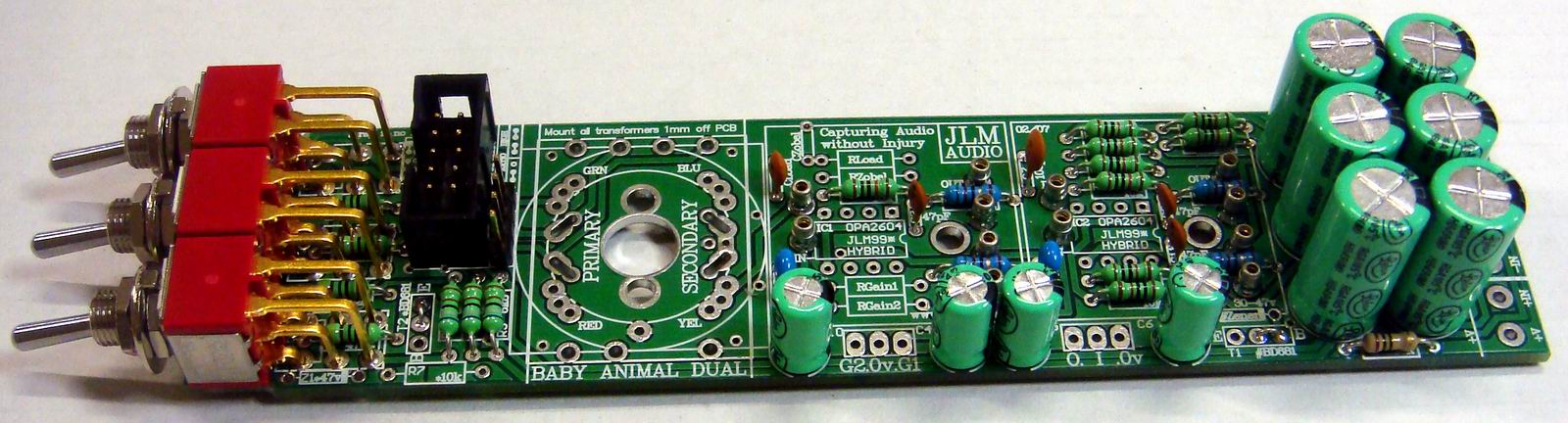
BAD PCB fully assembled except for 2 x 270R for RGain, input transformer and opamps Larger photo here
Notes & Errata#BD681 jumper is wrong in the photo below. Should be E-C. Also Dual99v does not use a Cload cap any more. So leave blank.

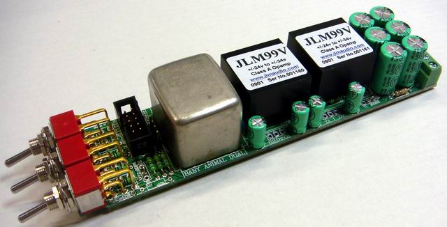
BAD PCB fully assembled as Dual99v (Note 2 links needed between centre pin and E on each BD681 position and 1mm gap under transformer)
Notes & Errata#BD681 jumper is wrong in the photo below. Should be E-C. Also Dual99v does not use a Cload cap any more. So leave blank.
Sit toggle hard against the PCB and solder one front support leg on each toggle to hold in place.
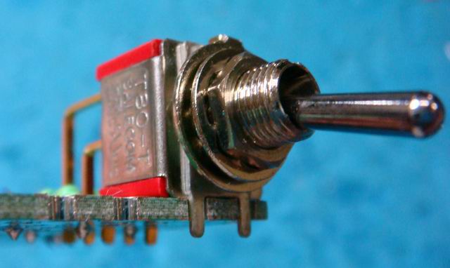
Check toggles level and square to each other and solder all legs and support pins
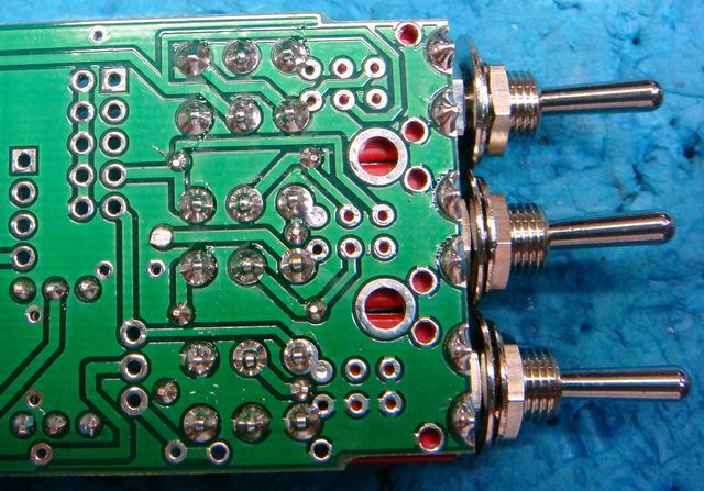
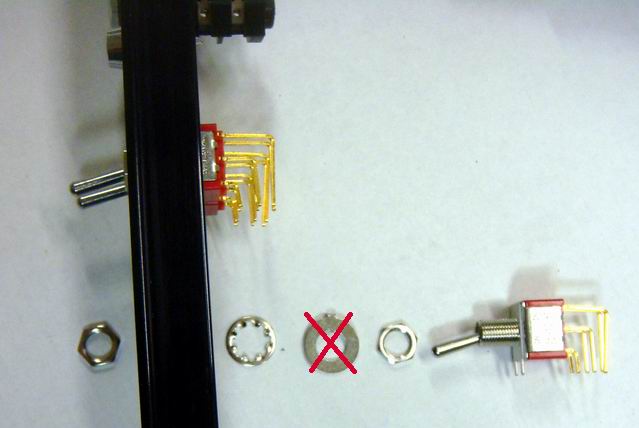
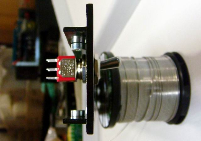
Dis-guard flat washer and fit the rear nut (should be a few mm gapped from the end of the thread) and washer to all three toggles
Nuts should just screw on an tighten with minimum thread sticking out if the rear nut is set correctly
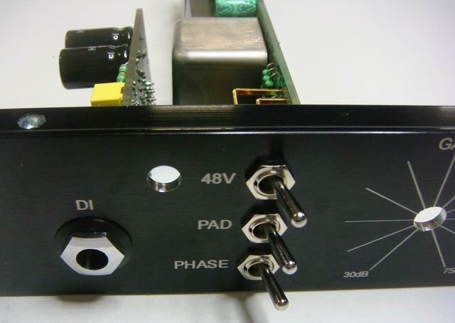
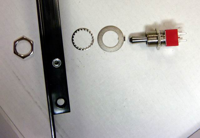
Nuts and washer order for Power switch
Same again space the rear nut up so the minimum of thread sticks out past front nut.
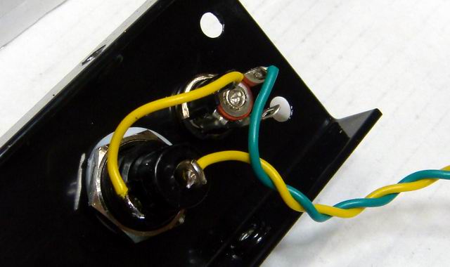
DC connector and Fuse wiring
All Pot wiring for BAD Dual99v PCB
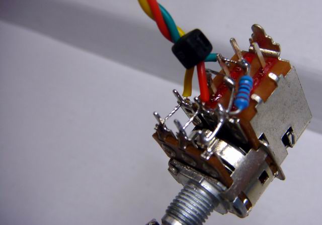
Gain pot wiring (Photo shows BAD/Dual99v dual pot)
Note BA is the same but only a single pot
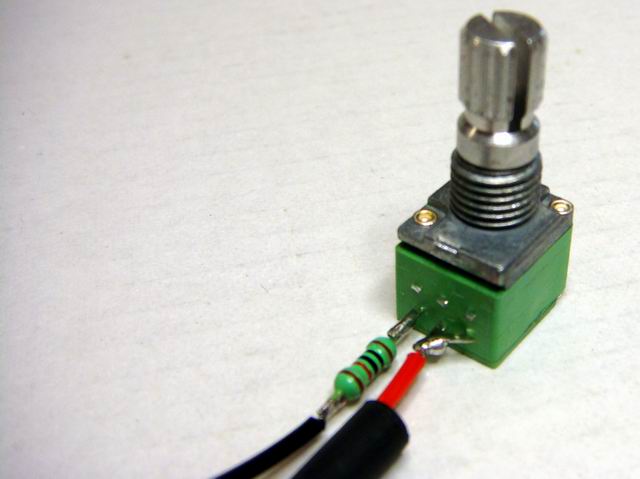
Output Pot wiring
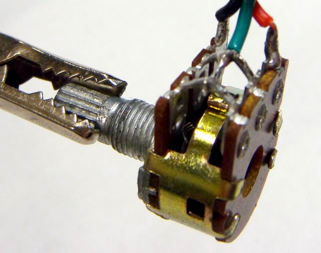
Z pot wiring
OEP/VTX = 10k in series with 100k log pot. (As shown in photo below for Dual99v)
JLM14 = 2k2 in series with 50k log pot (2k2 resistor solders to both pins on the left and red wire solders to all 4 pins on the right)
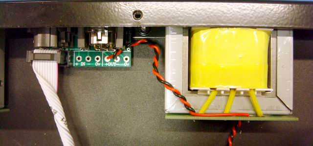
Output transformer to IOXLR PCB (Note link wire between -2 and +3 is hidden in this photo)
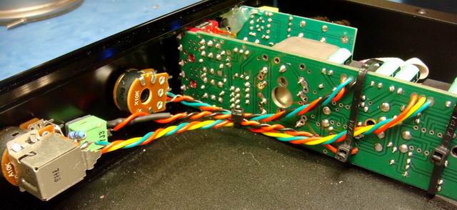
Full Dual99v internal wiring Larger photo here
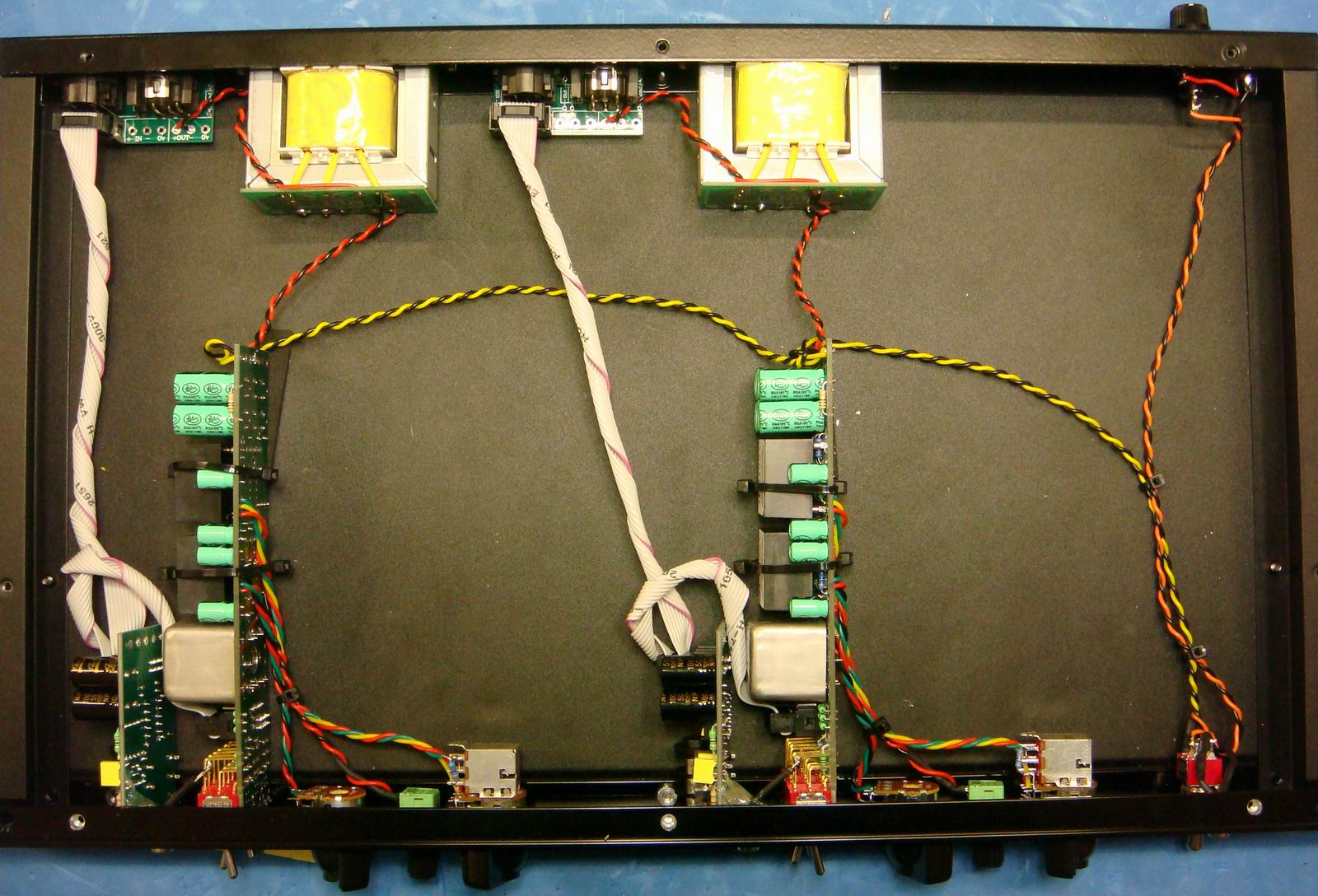
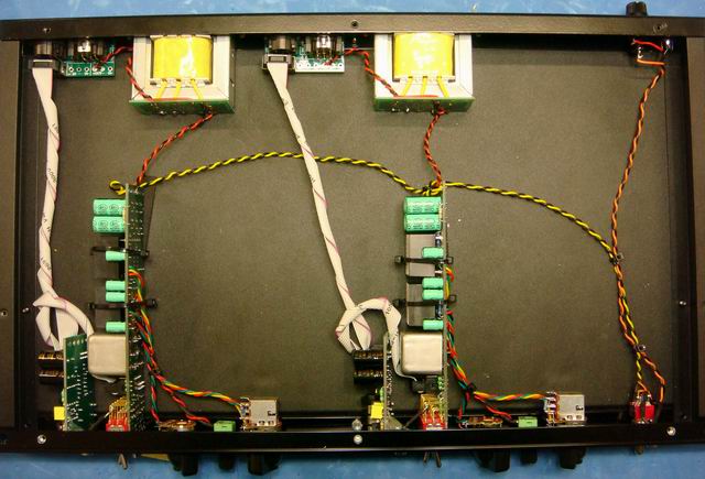 Errata[/color][/b][/u]#BD681 jumper is wrong in the photo below. Should be E-C. Also Dual99v does not use a Cload cap any more. So leave blank.
[img]http