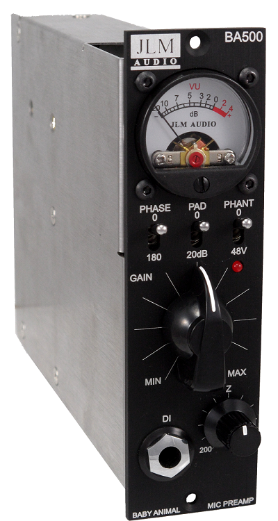
The BA500 is a 500/51x version of our well know Baby Animal mic pre.
BA500 Parts List here
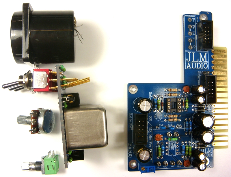
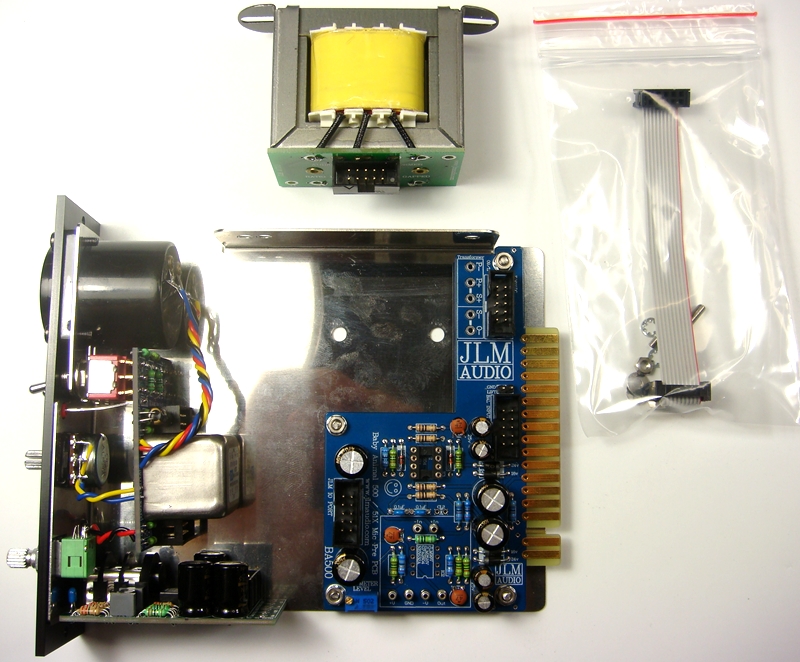
Complete BA500 kit with every part down to the last nut and bolt.
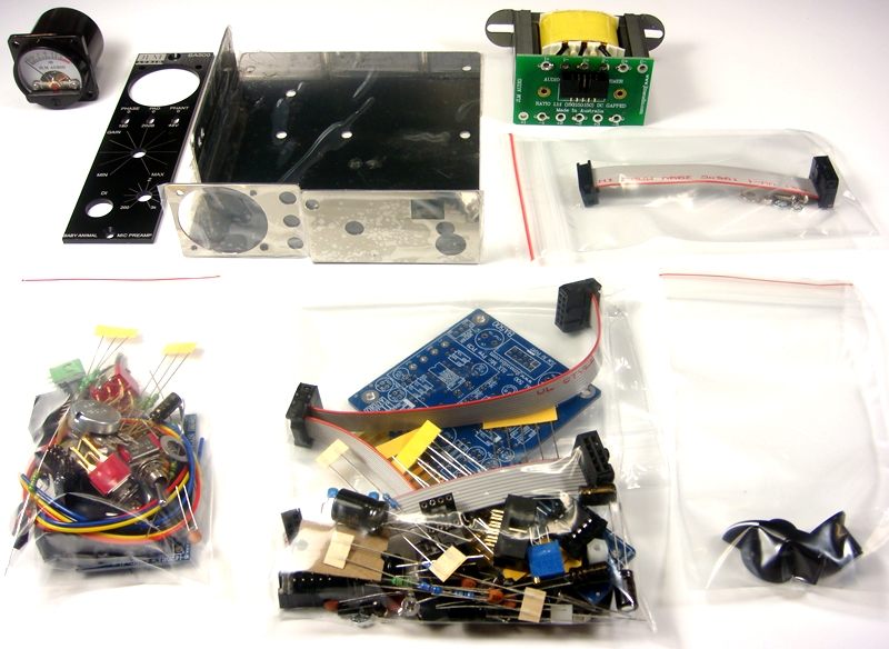
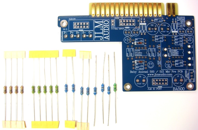
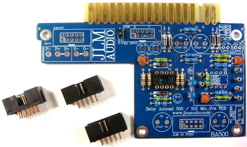
BA500 PCB kit
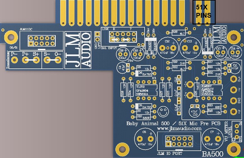
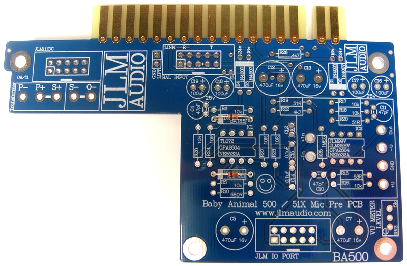
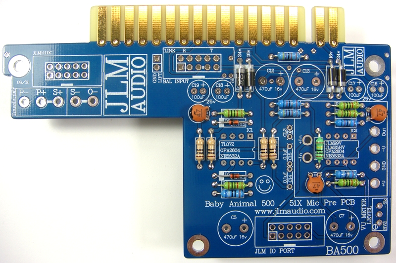
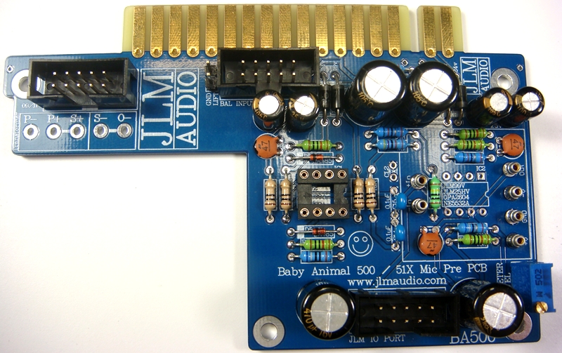
1. BA500 main pcb is a stripped down INX5 pcb so its overlay has the exact parts and values marked on it for the BA500 kit to make the build easy.
2. 51X and 500 compatible with 51X pins cut off. Kit fits all 500 and 51X racks and lunchboxes.
3. PCB automatically uses highest power available. +/-16v for 500 and +/-24v for 51X.
4. BA500 PCB also has mix buss out on pin 11 for Radial Workhorse racks.
BA500 Schematic here

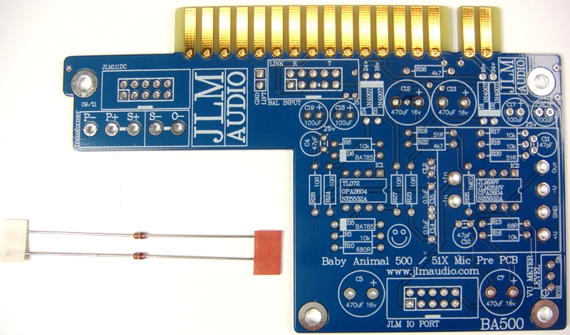
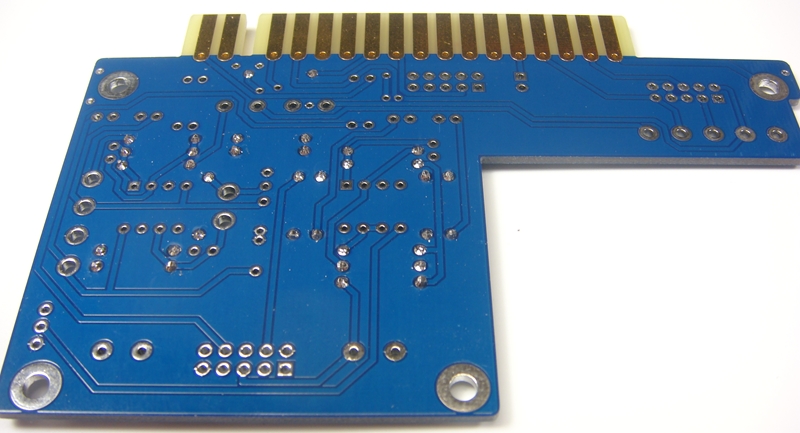
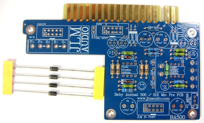
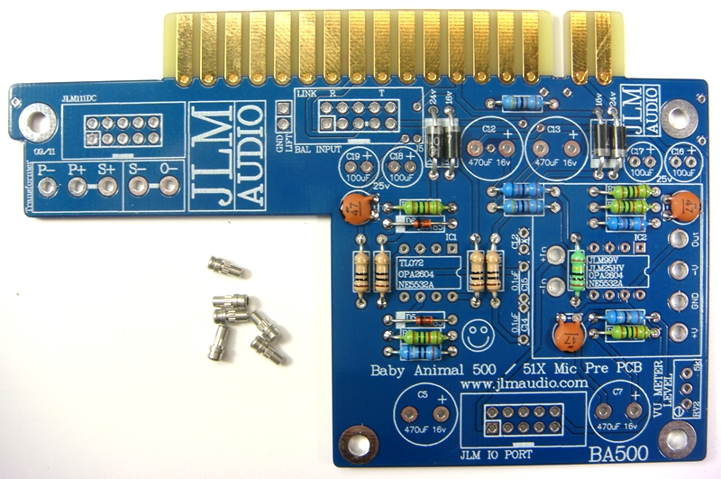
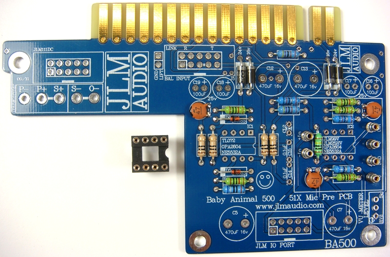
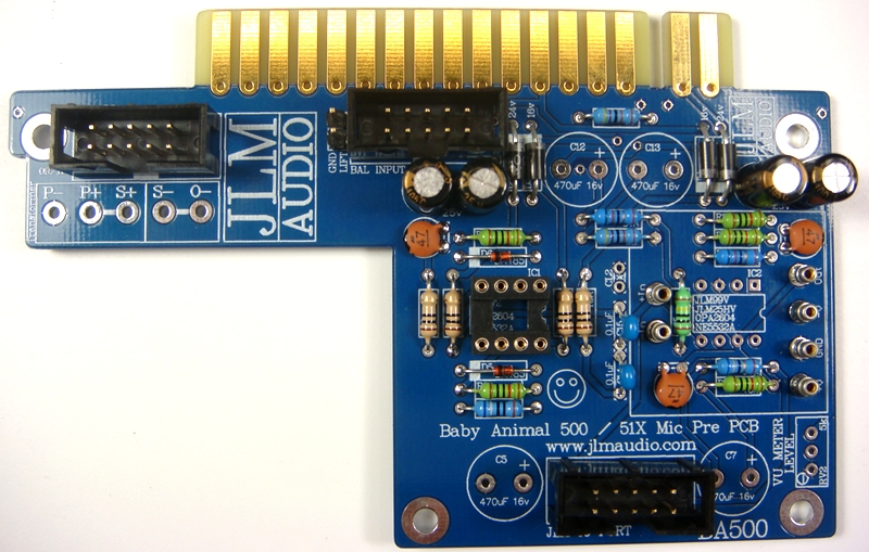
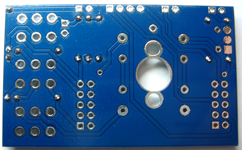
BA500 PCB. For 500 series racks cut and file 51X pins off)
Fit the two BAT85 diodes bending the legs sightly outwards to hold them in place.
Diodes are POLARIZED and must go in with there stripe matching the strip on the PCB overlay.
Solder the two BAT85 diodes bending the legs sightly outwards to hold them in place.
Cut BAT85 diode legs off at top of the solder joint and double check no solder joints missed soldering.
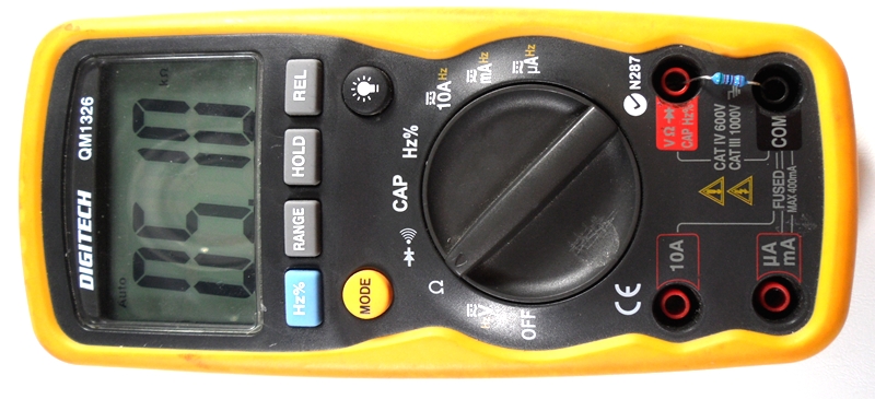
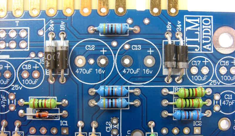
If you are not 100% with resistor colour codes use a multimeter to check values as you place the resistors
Fit all resistors at once bending the legs sightly outwards to hold them in place. This helps to make sure no resistors are put in the wrong position.
Note 1. Replacing R19 51R with new 33R give slightly better low frequencies response when using JLM111DC and JLM111DC compact output transformer.
In future kits we will be replacing all 51R with 33R. So R19 and R20 will both be changed to 33R on new PCBs.
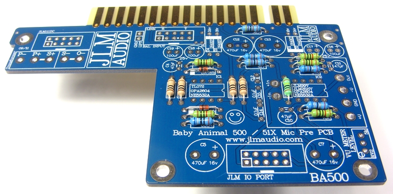
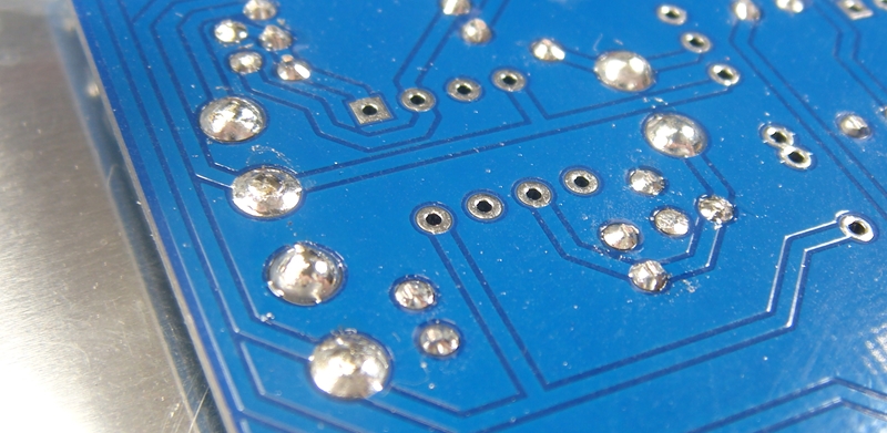
Solder all resistors while holding PCB firmly upside down on flat surface.
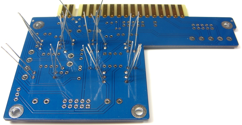
Cut all resistor legs off at top of the solder joint and double check no solder joints missed soldering.
Fit the 4 x 1N4007 diodes. Diodes are POLARIZED and must go in with there stripe matching the strip on the PCB overlay.
Solder 1N4007 diodes in once you have checked there POLARITY is correct.
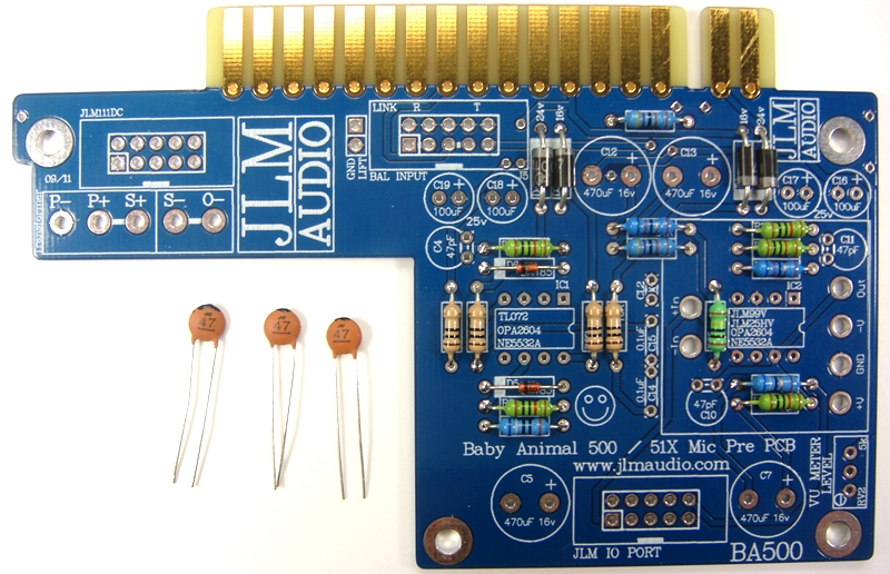
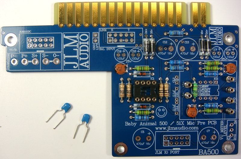
Fit 3 x 47pF ceramic caps in place. The 47pF caps are NOT Polarized so can go in either way around.
Fold 47pF caps down flat to PCB before soldering them.
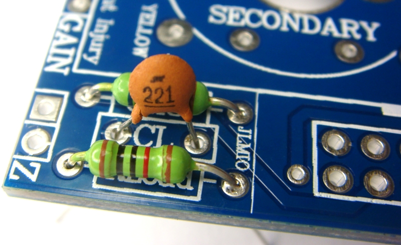
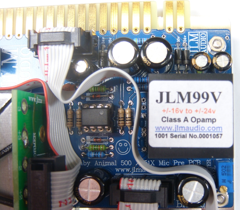
Note there is also a ceramic 220pF cap marked 221 that is for CL2 (Cload2) in the BA500 kit. Do NOT FIT CL2.
We have found NO CL2 is needed in the current configuration as long as Cload on the GO Between 500 is fitted.
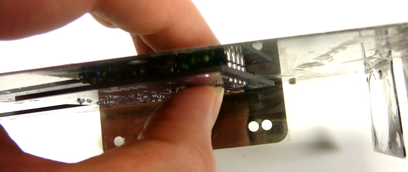
Fit 6 x 1mm sockets for 99v opamp. Do NOT press the sockets in. Just let them sit in the holes. Use a piece of cardboard or the stainless steel bracket to hold them in while turning the PCB over.
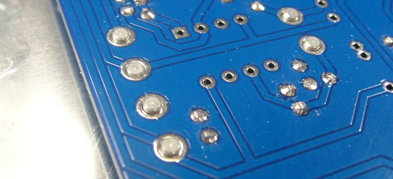
Solder 6 x 1mm sockets in place
Fit and solder DIP8 socket in other opamp position. Make sure the POLARIZED socket matches the PCB overlay.

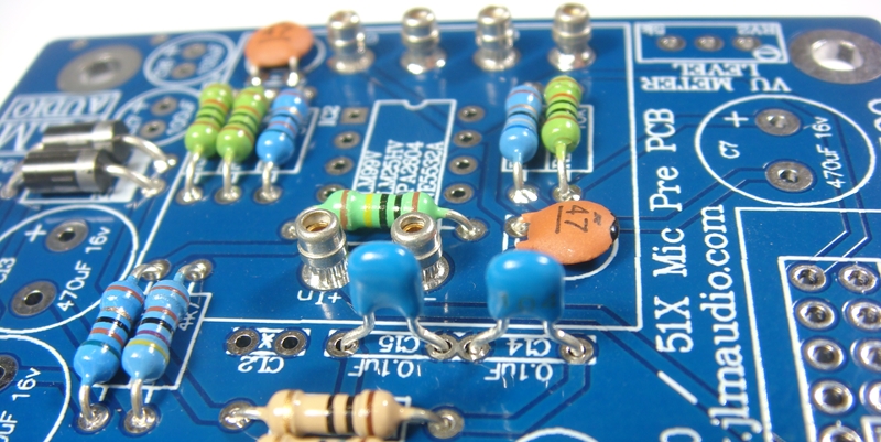
Fit and solder 2 x 0.1uF MONO caps in place. The 100nF caps are NOT Polarized so can go in either way around.
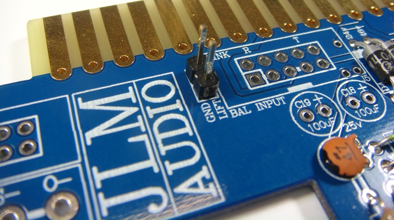
Fit and solder jumper pins in place

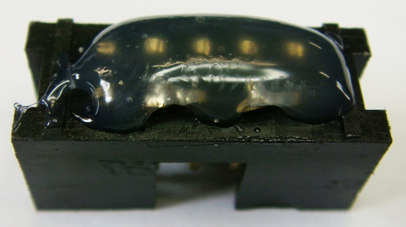
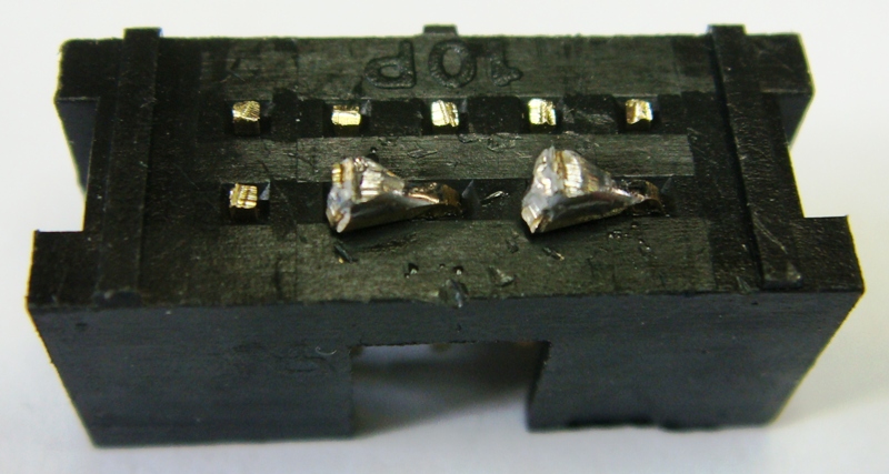
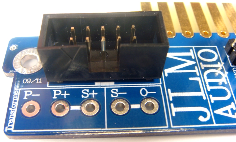
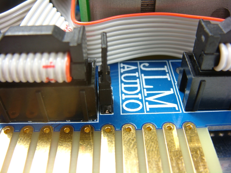
Fit and solder IDC headers in the POLARITY shown. Do not reverse. Triangle on header indicates pin 1 which is the square pad on the PCB.
The front opening in the IDC headers should both now be facing as shown below.
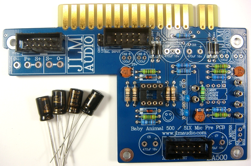
Fit and solder 4 x 100uF Electro caps to PCB. The 4 x 100uF caps are POLARIZED so must have there long positive leg fitted to + marked on PCB overlay.
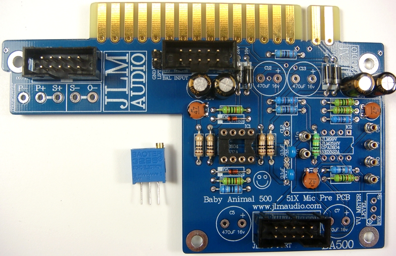
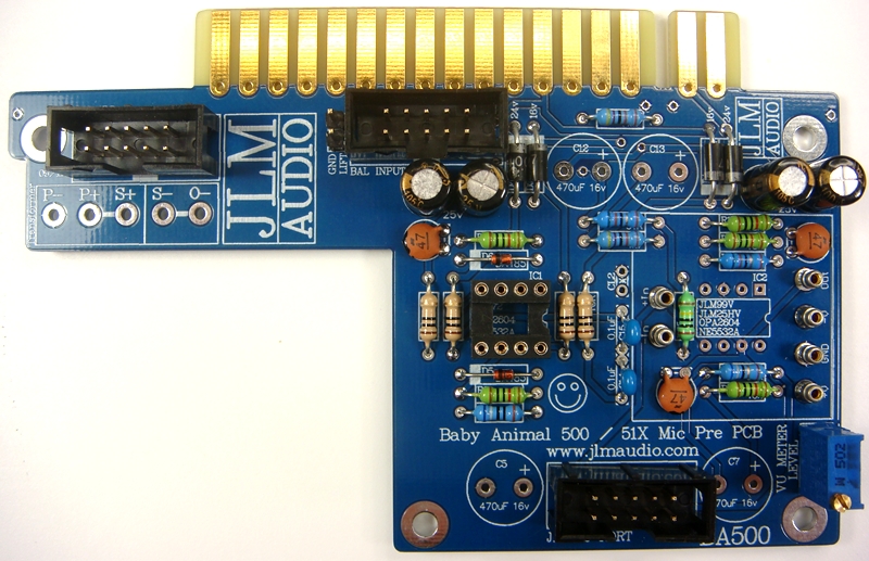
Fit and solder trim pot. The trim pot is POLARIZED so must go in as shown on PCB overlay. Adjustment screw should be as shown on overlay.
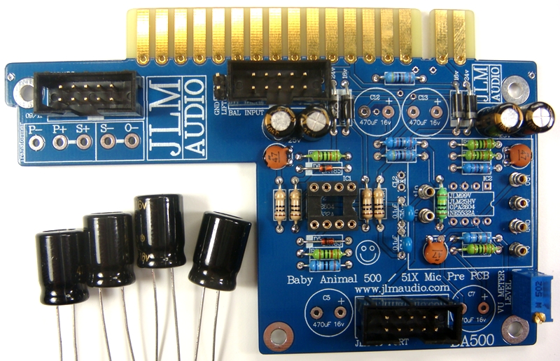
Fit and solder 4 x 470uF Electro caps to PCB. The 4 x 470uF caps are NON POLARIZED so can go in either way around.
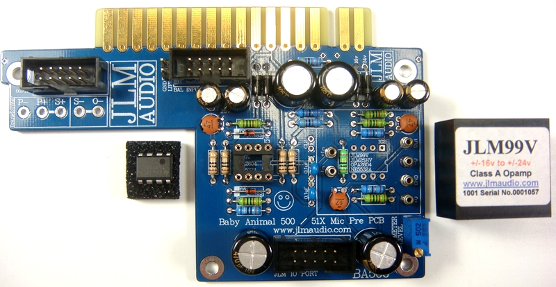
Fit OPA2604AP opamp in the correct POLARITY shown. 99v opamp can be fitted now or later. BA500 PCB is ready to go.
Put nuts and bolts etc back into zip lock bag the BA500 PCB kit came in to make sure they are not lost while you build the Small Go Between 500 PCB next.
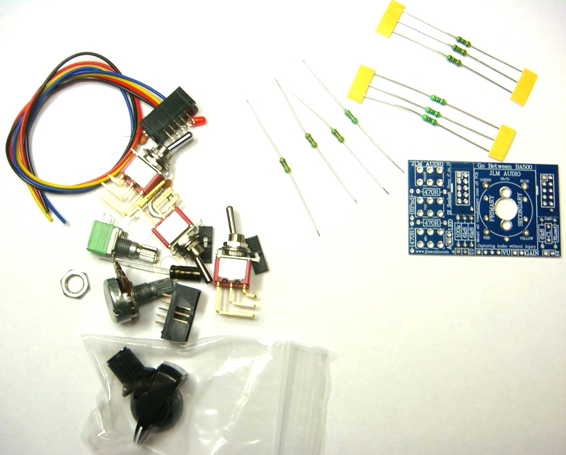
Go Between 500 kit
BA500 Schematic here
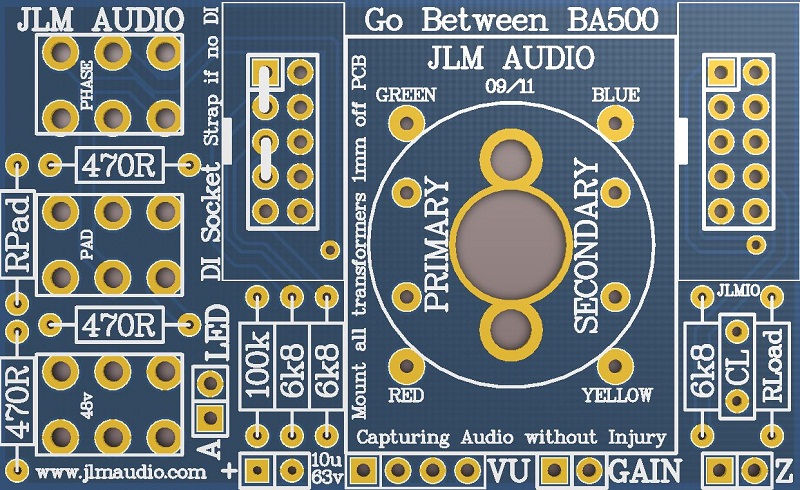
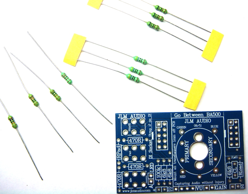
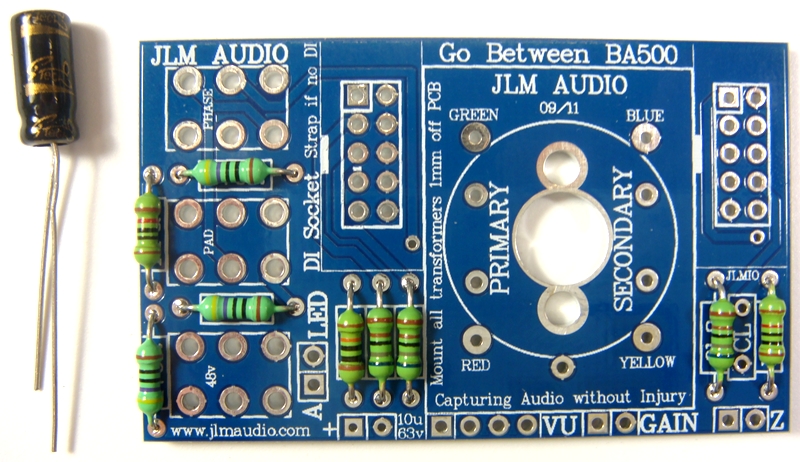
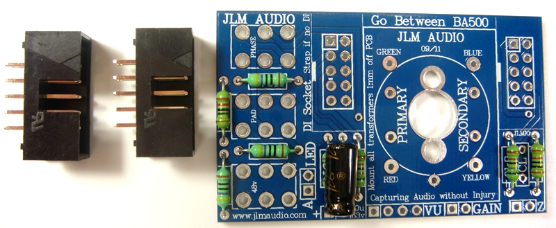
Go Between 500 PCB
If you are not 100% with resistor colour codes use a multimeter to check values as you place the resistors
Fit all resistors at once bending the legs sightly outwards to hold them in place. This helps to make sure no resistors are put in the wrong position.
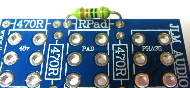
RPad is 120R for 20dB Pad (If you want unity gain with pad in and and gain at minimum make RPad 68R for 26dB Pad)
RLoad is 10k for OEP/VTX input transformer & JLM14 wired a 1:8 (Rload is 2k2 for JLM14 input transformer wired normally as 1:4)

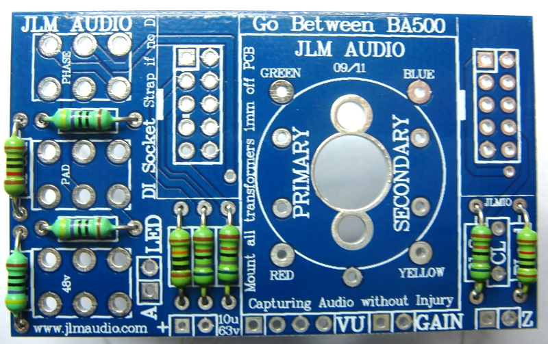
Solder all resistors while holding PCB firmly upside down on flat surface.
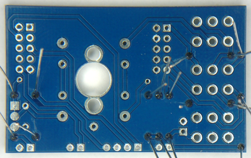
Cut all resistor legs off at top of the solder joint and double check no solder joints missed soldering.
Fit Cload 220pF ceramic caps in place. The 220pF cap is NOT Polarized so can go in either way around.
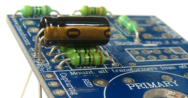
Fit & Fold cap as shown and solder 10uF Electro caps to PCB. The 10uF cap is POLARIZED so must have there long positive leg fitted to + marked on PCB overlay.
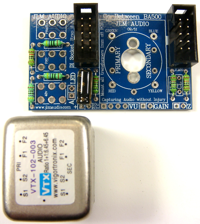
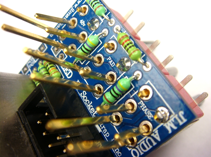
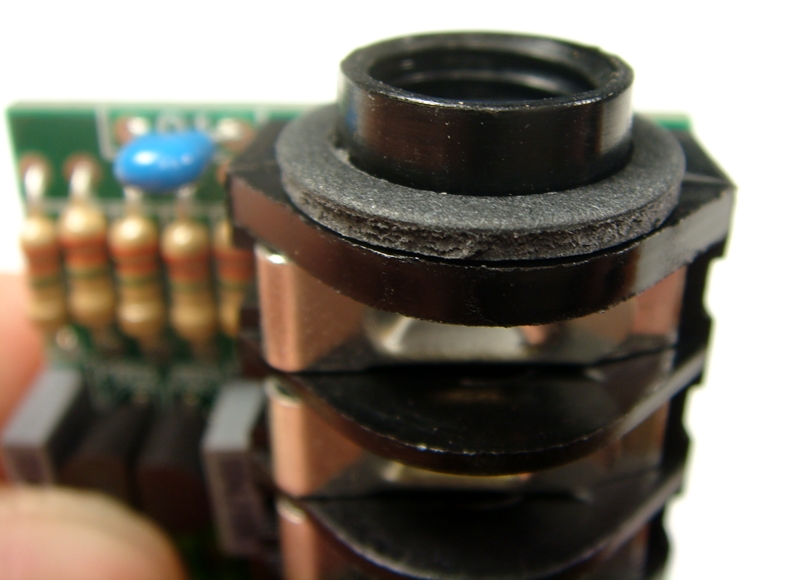
Fit and solder IDC headers in the POLARITY shown. Do not reverse. Triangle on header indicates pin 1 which is the square pad on the PCB. Trim back plastic ribs on header with its back against OEP/VTX transformer.
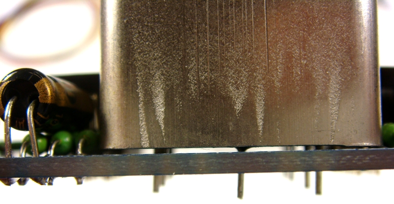
Fit OEP/VTX input transformer with 1mm gap from PCB and solder in place. It can only fit to the PCB one way around.
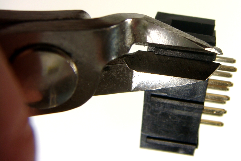
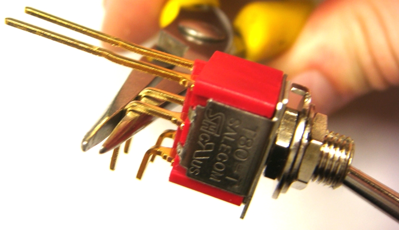
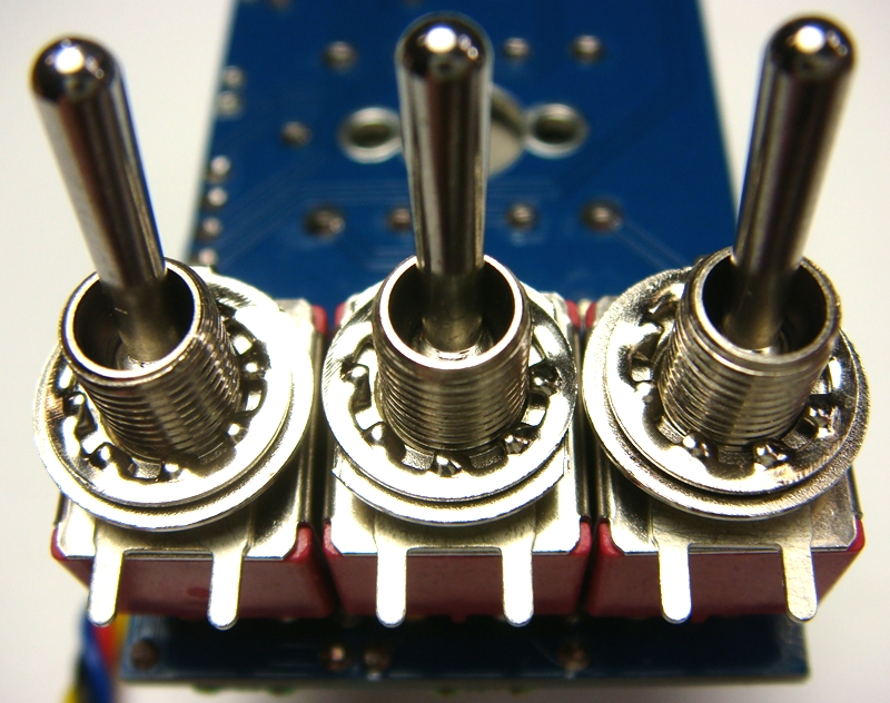
The three switches for the Go Between 500 need have to have there 6 legs straightened with a set of small long nose pliers like below.
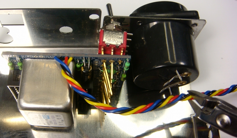
Fit switches as shown below so the PCB is at 90 degrees to the toggle.
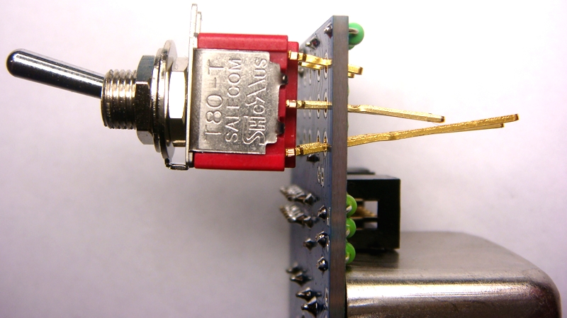
Line the three switches up and solder one terminal on each switch as shown below.
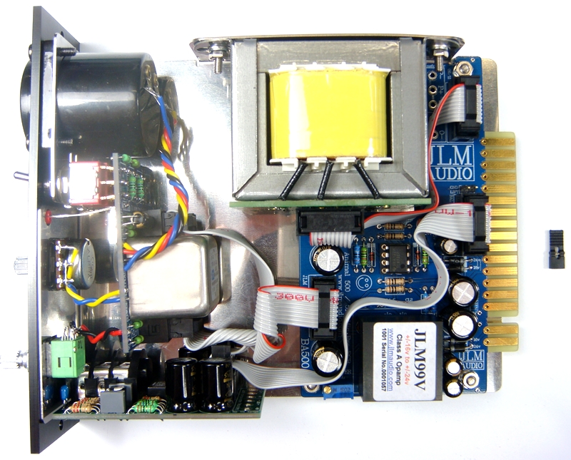
PCB's are now ready for final assembly
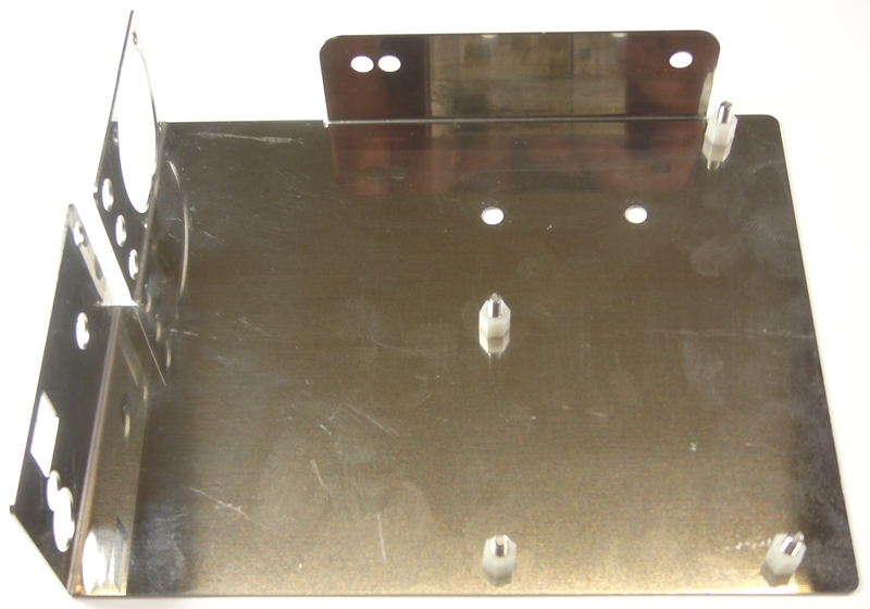
Fit the 4 x 12mm countersunk screws found in the LA500 PCB kit to the bracket and screw 6mm nylon spacers to them.
Nylon spacers have countersink on one side that should go down on to the bracket to take the protruding part of screws countersink.
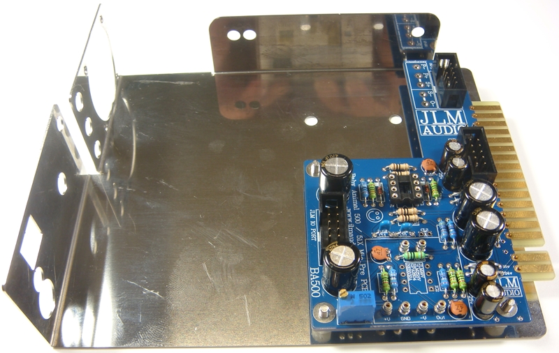
Last chance to cut off 51X pins if converting the PCB to a 500 version.
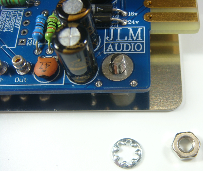
Fit BA500 PCB and hold down with shakeproof washers and nuts provided in the BA500 PCB kit.
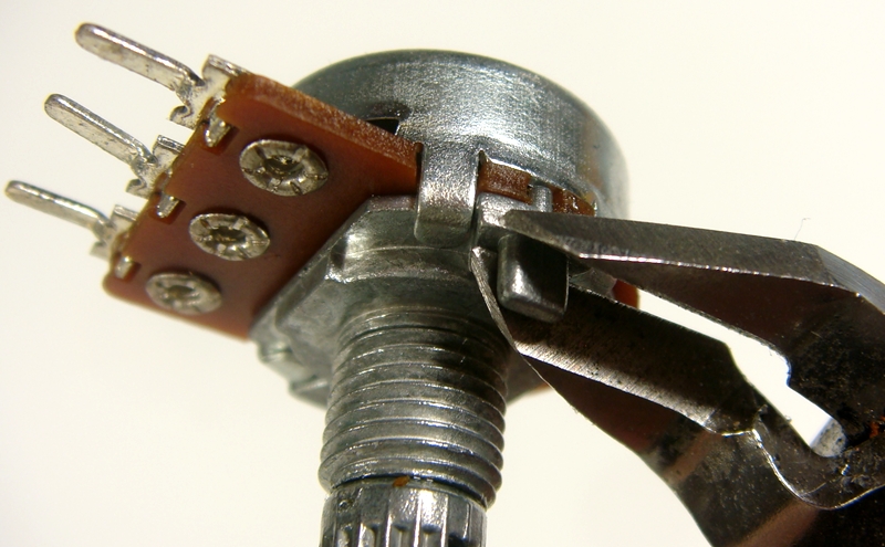
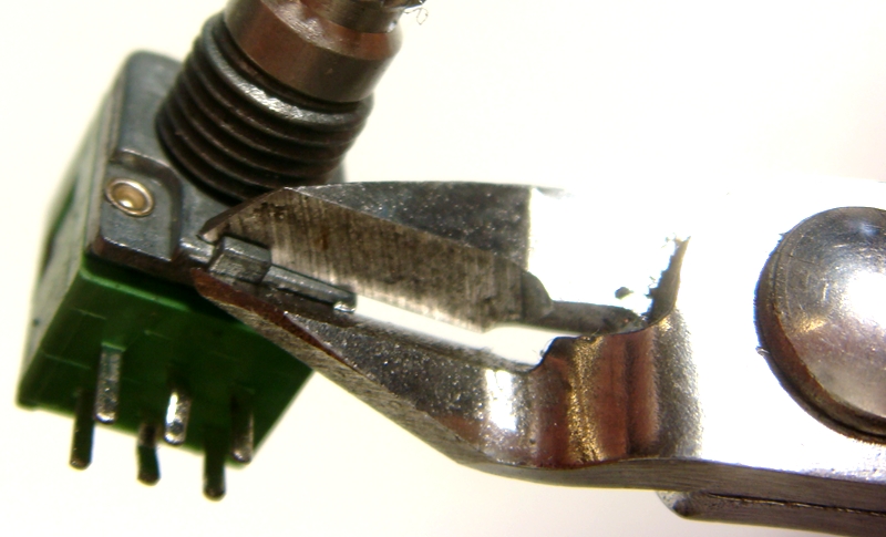
Remove locate tags on both pots with sidecutters as shown below.
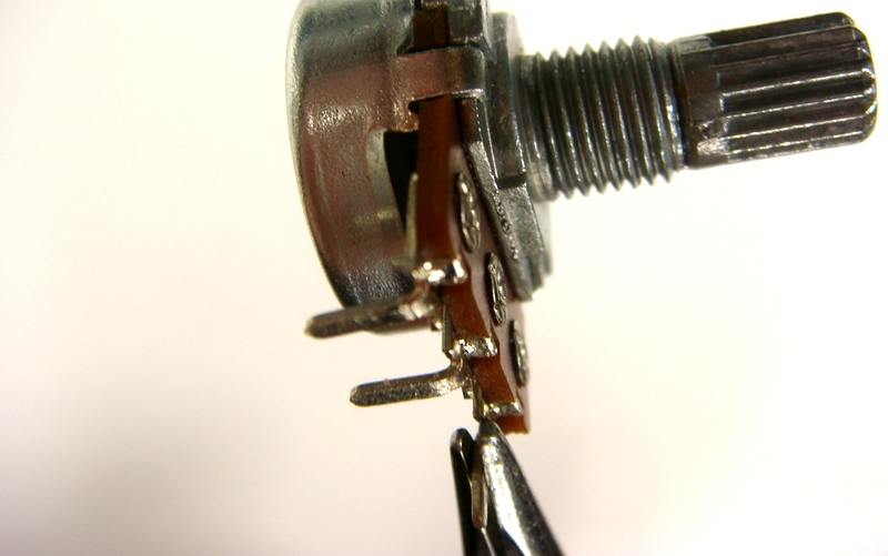
Fold legs 90 degrees with long nose pliers to make soldering easier later.
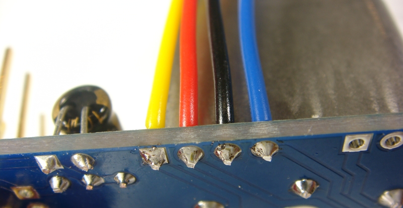
Strip 5mm of insulation of the 4 wire colours provided and twist wire strands together and tin with solder.
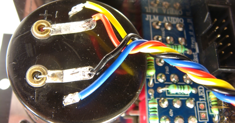
Place colours as shown for meter in GO between 500 PCB and solder in place.
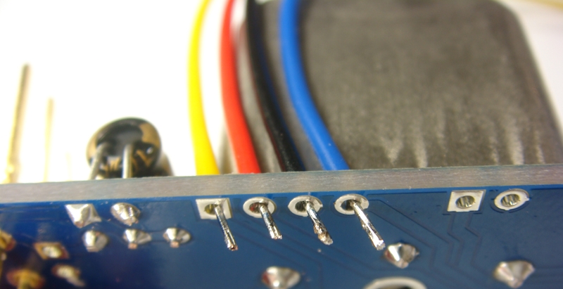
Solder into GO Between 500 PCB and cut excess off.
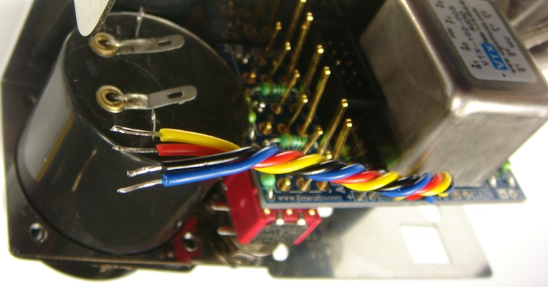
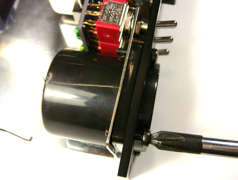
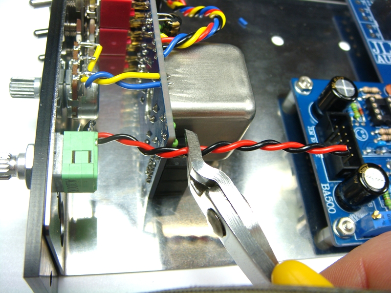
Fit meter into bracket and hold in place with one or 2 bolts hand tight. Twist 4 wires and cut to length.
Strip 5mm of insulation of the 4 wires and twist wire strands together and tin with solder.
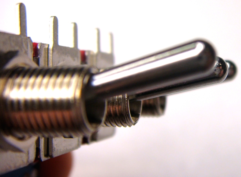
Wind the back nut fully down on to the 3 switches. Fit the flat washers on next.
Cut the sides of the middle flat washers with sidecutters so it does not overlap the other washers.
Fit the 3 shake proof washers on next. Fit to bracket and put on second nut and tighten.
Solder all toggle terminals and cut excess off.
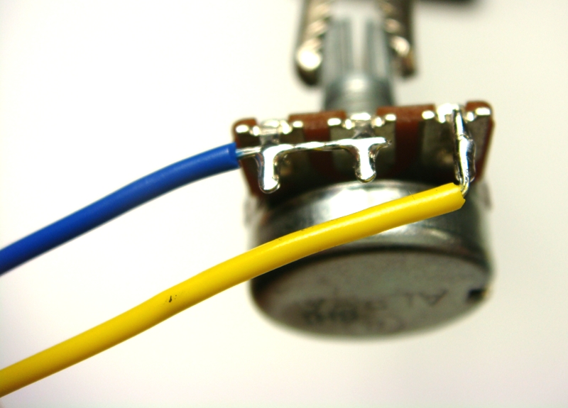
Solder wires to gain pot as shown.
Solder wires to Z pot as shown for OEP/VTX 100k pot. (Link unused front pot tags to back pot tags to make 50k pot for JLM14)
Fit front panel and hold in place with nut on gain pot.
Fit the 4 meter screws in GENTLY and do NOT over-tighten them or you may strip the bracket thread. Lock-tight can be useful in a always traveling lunchbox to stop them shacking loose.
Solder colours as shown on the meter terminals.
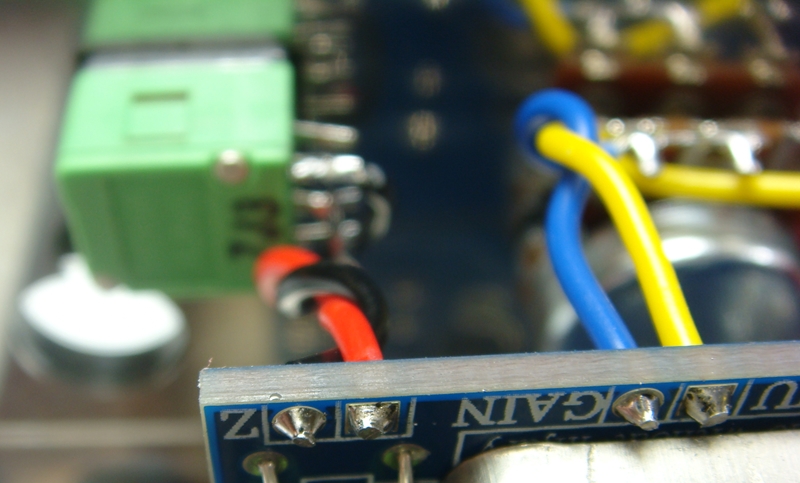
Trim gain pot wires and strip and tin them and solder to Go Between 500 pCB as shown below.
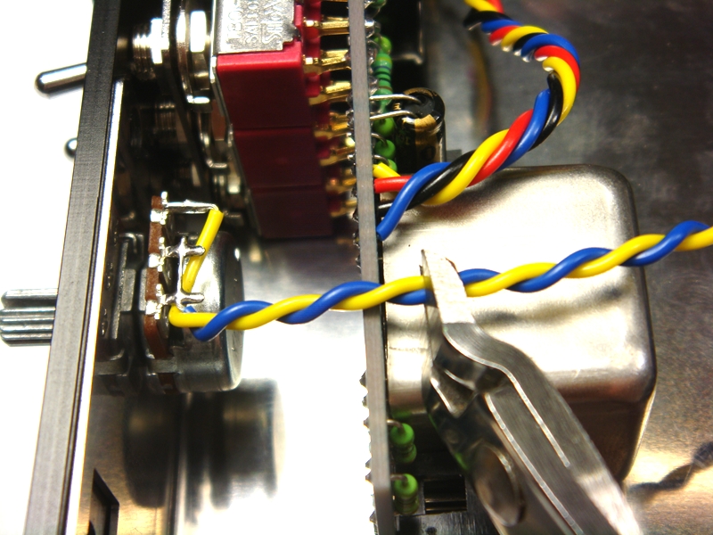
Trim Z pot wires and strip and tin them and solder to Go Between 500 PCB as shown below.
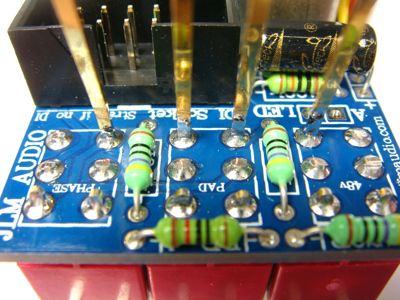
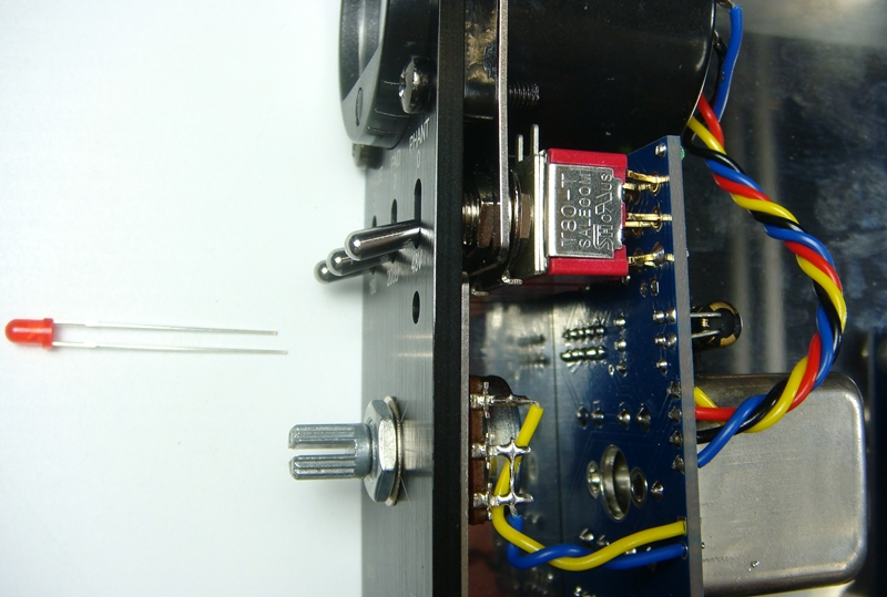
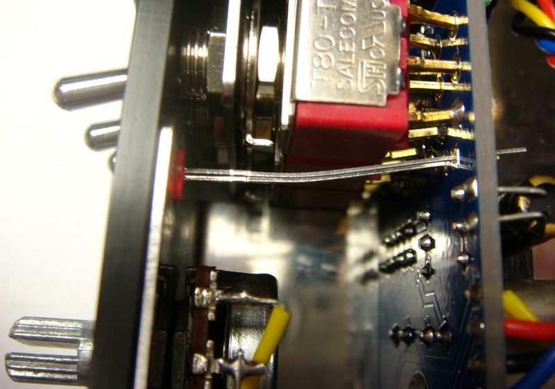
Fit 48v LED into GO between PCB and then push into front panel hole and solder and trim.
long LED leg shoudl go into the square solder PAD with the A beside it.
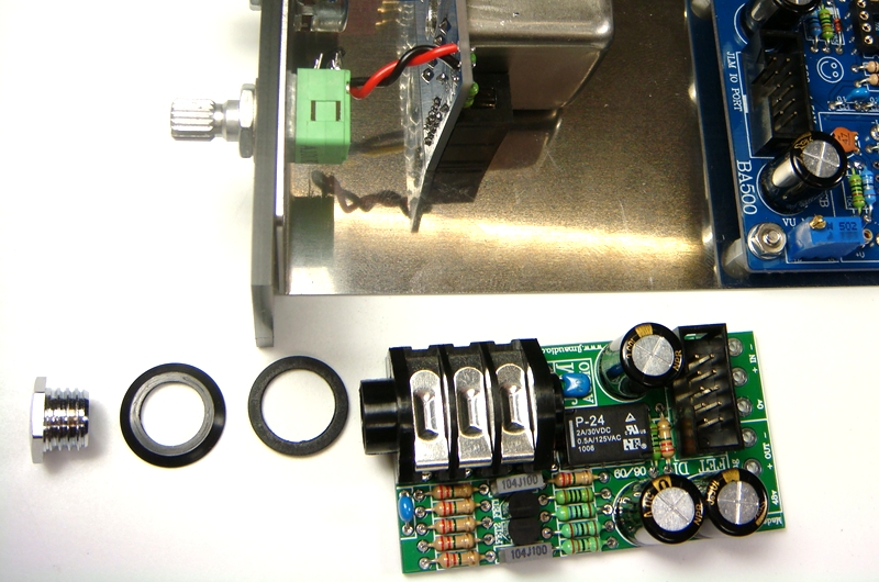
If you have ordered the FET DI kit fit to front panel as shown below. If no DI fit the 11mm blanking plug.
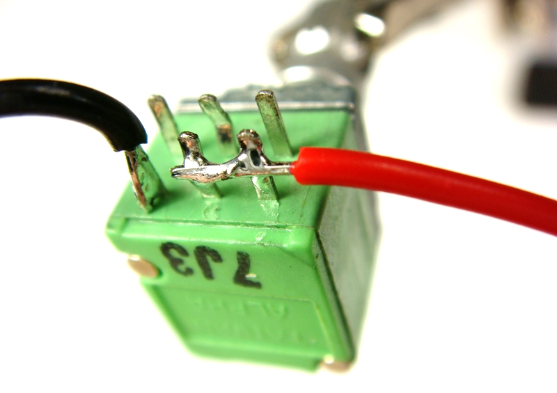
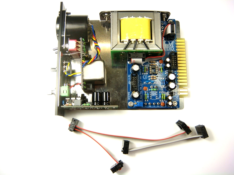
JLM111DC with wiring and hardware pack. Be warned do NOT touch the 3 yellow and black wires while handling the transformer as these are very thin wires and can easily be broken
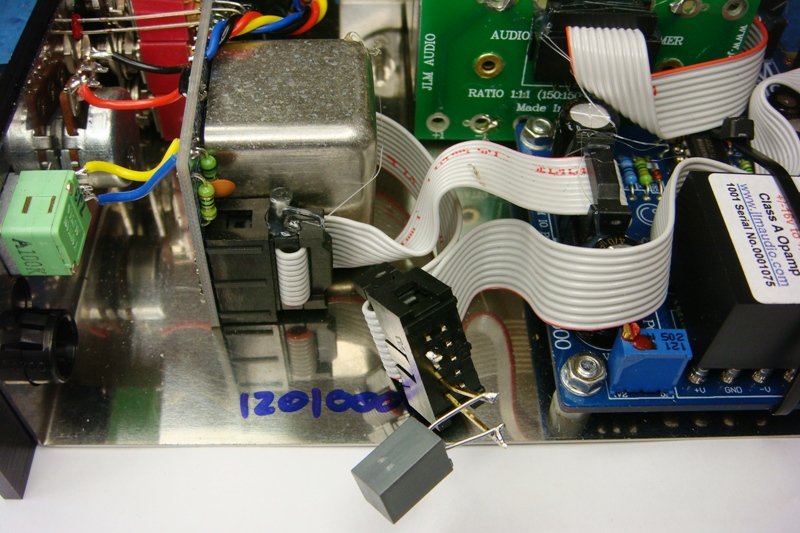
Fit ribbon cable between JLM111DC transformer and JLM111DC header on LA500 PCB.
Use shallow ribbon cable end with no cable relief clip fitted at the transformer end.
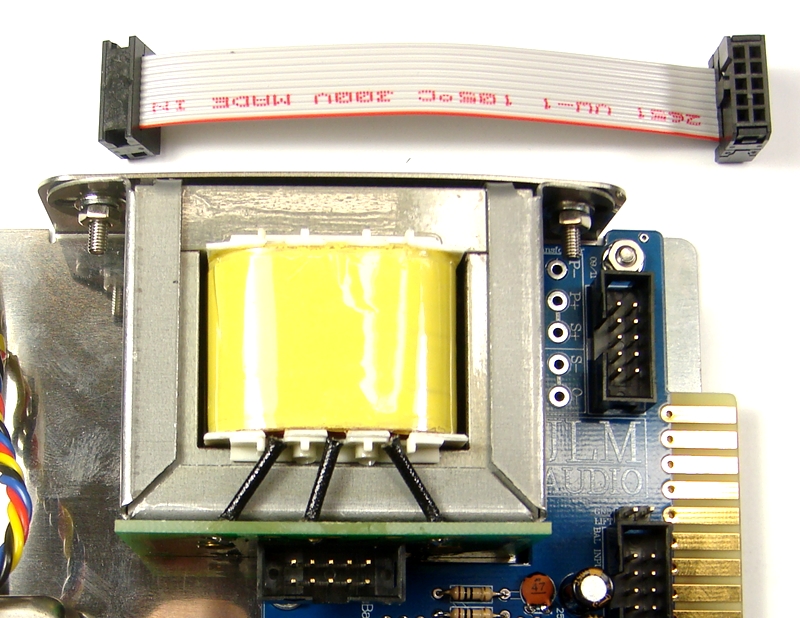
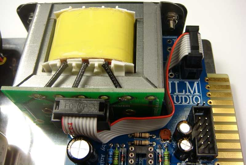
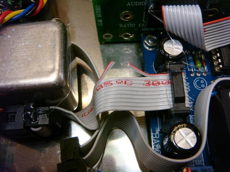
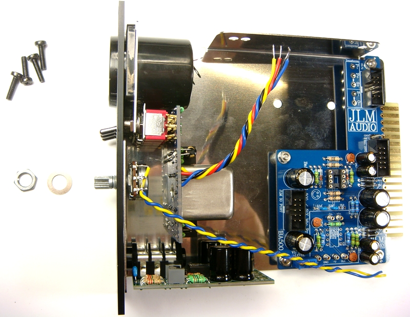
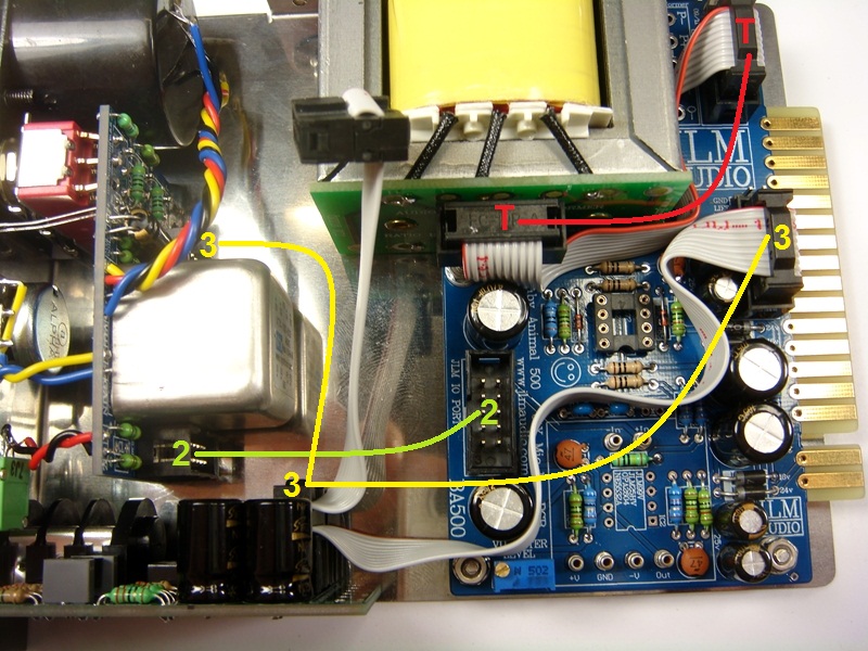
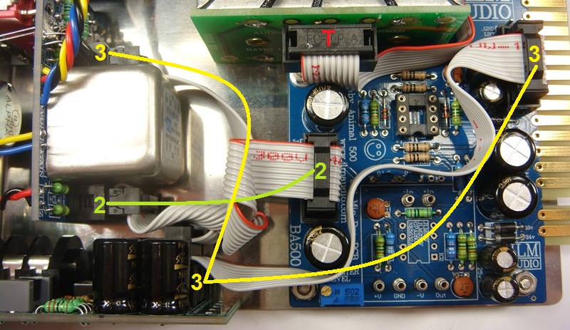
Fit ribbon cables provided to join the GO Between PCB headers to the BA500 headers as shown below.
Double check you have all headers on PCB correct way around and check red wire in ribbon cable lines up to triangle on header that marks pin 1 square solder pad.
Fit opamps to there socket as shown below. Note TL072 opamp pin 1 circle is closest the 99v.
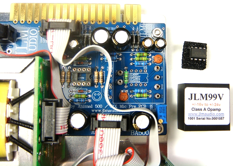
Fit GND jumper as shown below
Ready to test
Adjust blue 25 turn trim pot with small screw driver to get the VU meter 0VU point to line up to the reference level you want with a 1khz tone. Usually this would be +4dBM or 12 to 14dB down from 0dFS of your A/D.com/BA500/102%20Gain%20pot%20wiringJPG[/img]
Fit 48v LED into GO between PCB and then push into front panel hole and solder and trim.
long LED leg shoudl go into the square solder PAD with the A beside it.
[img]http