
Build Map at link below with PEQ500A pcb parts assembly order.
http://www.jlmaudio.com/builds/maps/PEQ500A_map.html
Build Photos below. You must be signed into the forum to see attachments.
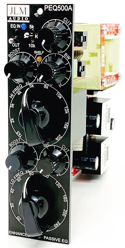
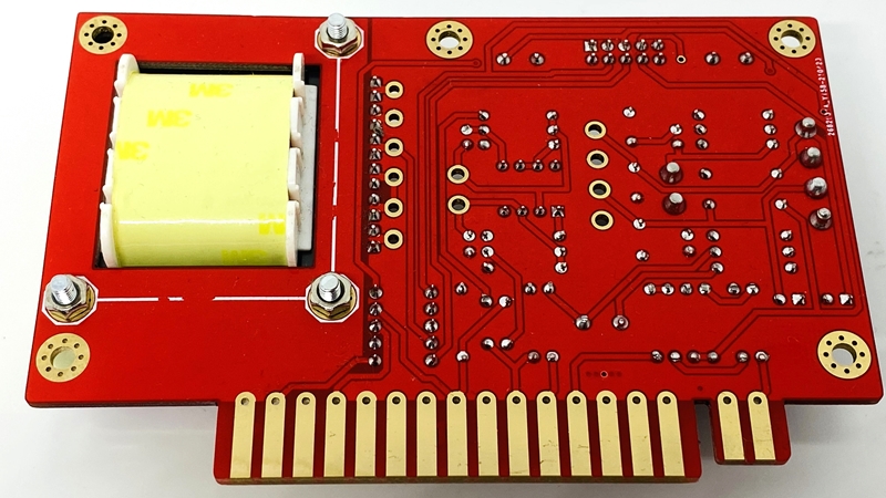
PEQ500A inside Top of PEQ500A PCB Bottom of PEQ500A PCB which comes with all precision SMD C0G caps & resistors fitted Break up PCB into sections with minimum flexing of the board Be careful while soldering not to damage any of the SMD parts under the PCB
There is a lot of room and not much soldering to be done so turn the PCB for best angle for easy soldering LO PCB parts LO PCB Built HI PCB Parts HI PCB Built (Cut off locate pin and solder 2 solder pads together) SWITCH PCB Parts SWITCH PCB Built EQ PCB Parts
WARNING If you have 24v relays (P24) in your kit do NOT fit them. Contact us for correct 12v (P12) relays
(screw down inductor firmly with black screw provided before soldering it in) EQ PCB Built Stick 6mm rubber foot to bottom of EQ PCB under inductor for extra support. PEQ500A Assembly
Double check you have cut of locate tab on dual 10k pot/switch
Fit HI PCB to front panel and do up the 2 x 10mm nuts tight. Bend short leg of orange LED down slightly less than 90degrees.
Then bend long leg of orange LED down slightly less than 90degrees.
The short leg will down be longer and goes in the pad closest to the front of the pcb. Fit orange LED to pcb and shelf panel hole and solder and trim legs Fit SWITCH PCB to front panel
Tighten 3mm bolt to standoff and 10mm nut to front panel Bend short leg of blue LED down slightly less than 90degrees
Then bend long leg of blue LED down slightly less than 90degrees
Cut blue tube into 2 x 10mm and fit over LED legs and trim legs to 15 to 17mm long
The short leg will down be longer and goes in the pad closest to the front of the pcb. Fit blue LED to pcb and EQ IN panel hole and solder and trim legs Fit LO PCB to front panel Fit EQ PCB to bracket and front panel and do up both 12mm nuts
Remove clear protective plastic from front of bracket first Plugin 6 pin cable between EQ & LO PCB
Plugin 10 pin 3 header cable between EQ & HI & SWITCH PCB PEQ500A ready for adding BIO500T PCB
(Do not fit Knobs until EQ is fully tested as they can be hard to get off)
When fitting knobs check all controls are fully CCW and try knobs just slightly on T18 spline to check dial lines up.
Swap knobs between pot splines until they all line up correctly before pushing them fully down the shaft.
If you need to remove a knob the break-off pieces of pcb left over are good between the front panel and a flat screwdriver
to stop marking the front panel as you lever off the knob

NEW BIO500T PCB schematic http://www.jlmaudio.com/BIO500/BIO500T%20Schematic%20210519.pdf
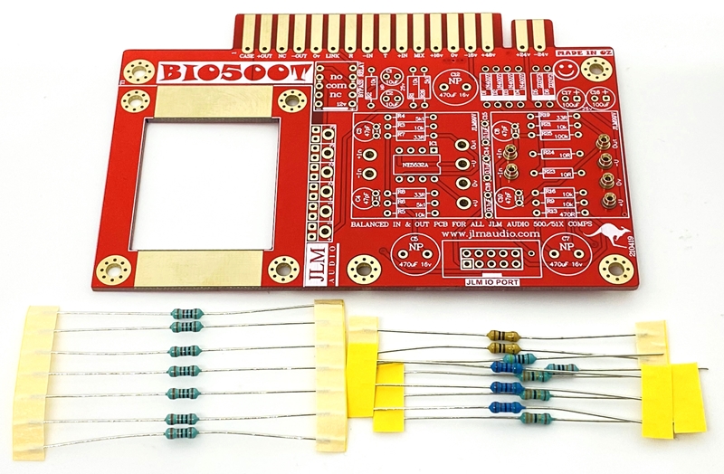
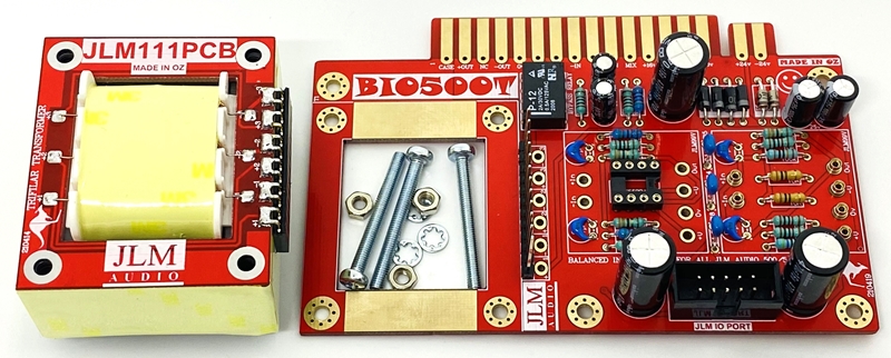
BIO500T PCB kit
Fully 51X and 500 compatible. 51X pins shorter so PCB will plug into 500 rack without having to cut them off.
PCB automatically uses the highest power available. +/-16v for 500 and +/-24v for 51X.
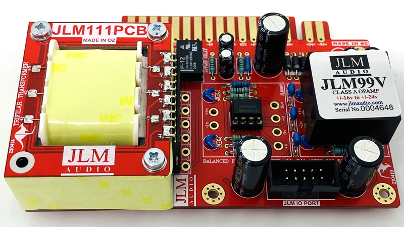
PEQ500A version of BIO500T comes with 2 x JLM99v and 12 x 1mm socket pins instead of NE5532A and DIP8 socket

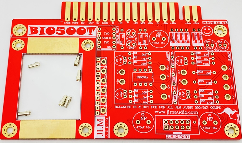
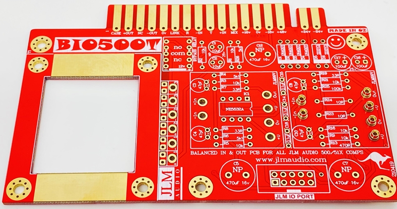
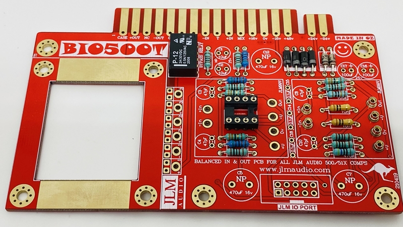
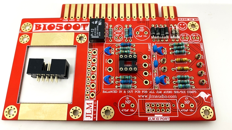
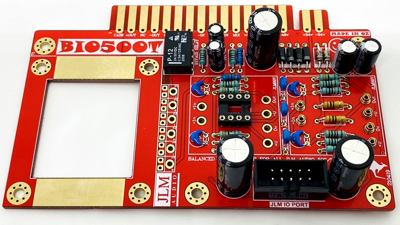
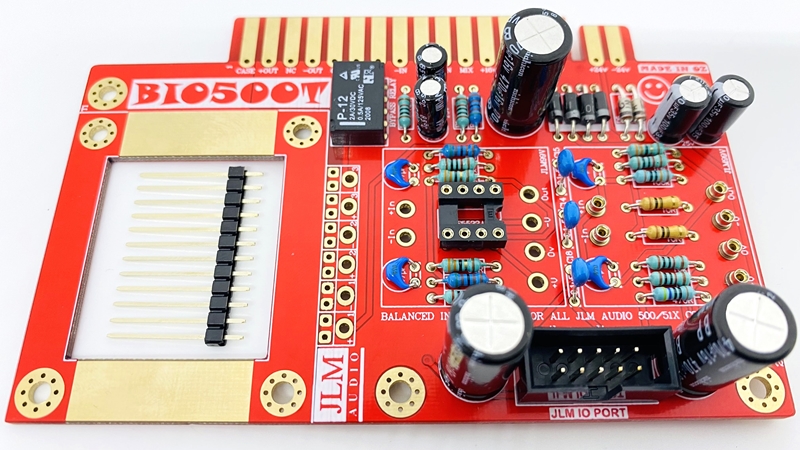
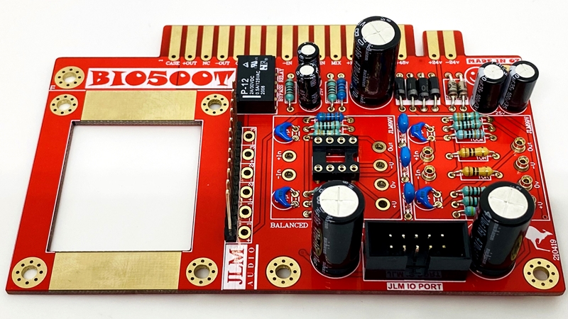
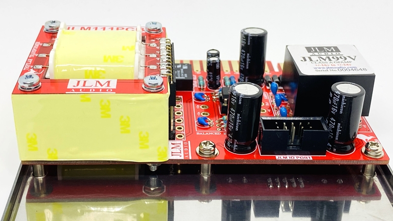
BIO500T PCB.
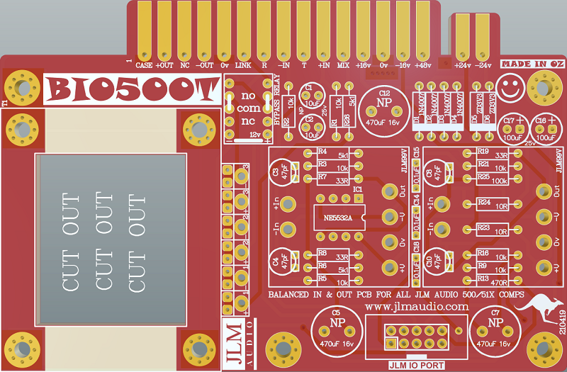
Fit 12 x 1mm sockets for 2 x 99v opamp. Do NOT press the sockets in. Just let them sit in the holes.
Use a piece of cardboard to hold them in while turning the PCB over.
(Photo shows LA500A version with 6 sockets but PEQ500A uses all 12 sockets for 2 x JLM99v opamps instead)
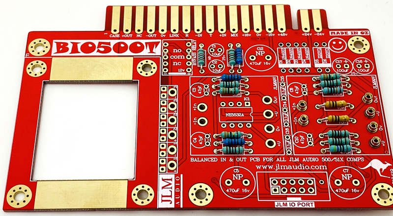
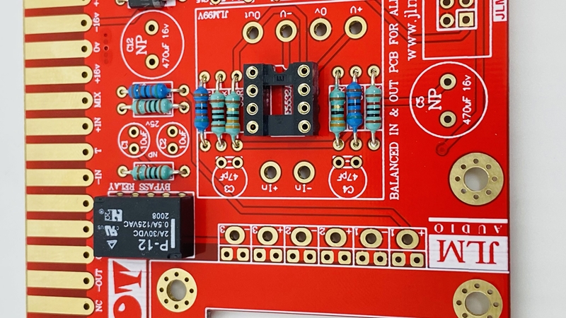
If you are not 100% with resistor colour codes use a multimeter to check values as you place the resistors
Fit all resistors at once bending the legs slightly outwards to hold them in place. This helps to make sure no resistors are put in the wrong position.
Solder all resistors while holding PCB firmly upside down on a flat surface.
Cut all resistor legs off at top of the solder joint and double-check no solder joints missed soldering.
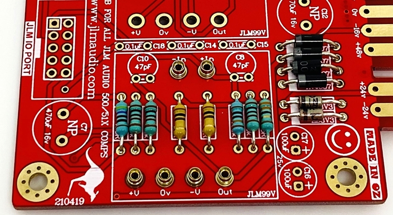
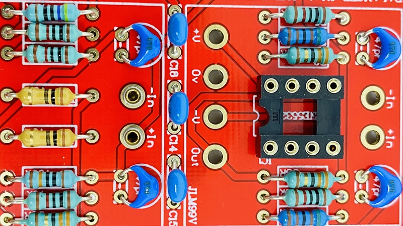
Fit the 4 x 1N4007 diodes (& 2 x 3v3 Zener diodes BIO500v2). D1 to D6 Diodes are POLARIZED and must go in with their stripe matching the strip on the PCB overlay. Solder diodes in once you have checked their POLARITY is correct.


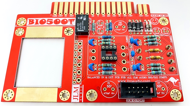
Fit and solder Relay (DIP8 socket not used in PEQ500A). Make sure the POLARIZED socket matches the PCB overlay. Bend 2 legs out to hold the relay in place for soldering. Solder relay in place once POLARITY has been checked.
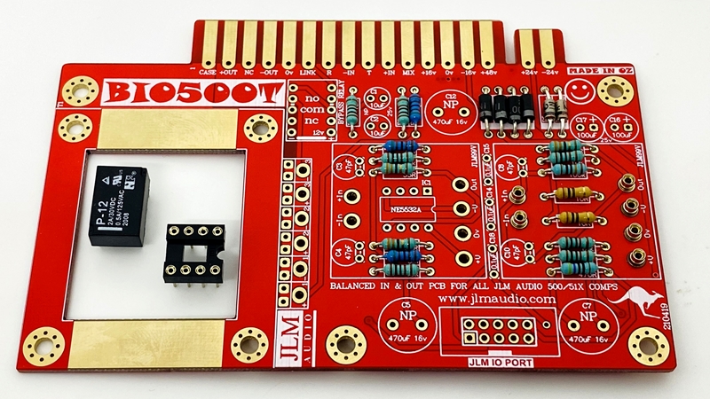
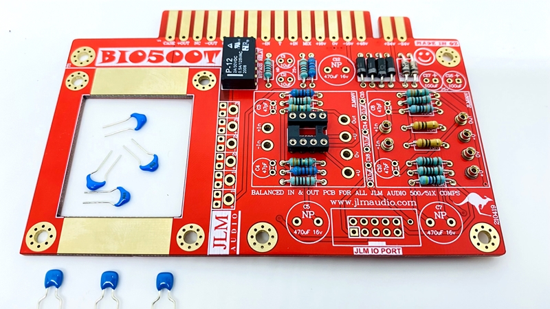
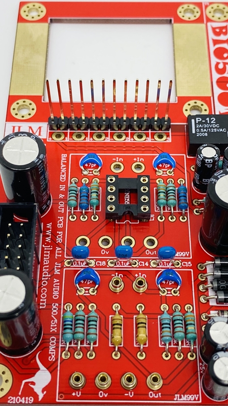
Fit and solder 3 x 0.1uF MONO caps & 4 x 47pF in place. The 100nF & 47pF caps are NOT Polarized so can go in either way around.
Caps 01.uF should be marked 104 or 0.1u or 100n. 47pF should be marked 470 or 47p. Fold 47pF caps down flat to PCB before soldering them.

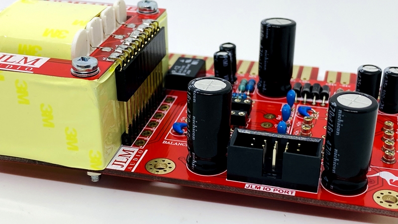
Fit and solder IDC headers in the POLARITY shown. Do not reverse. The triangle on the header indicates pin 1 which is the square pad on the PCB.
The front opening in the IDC headers should both now be facing as shown below.

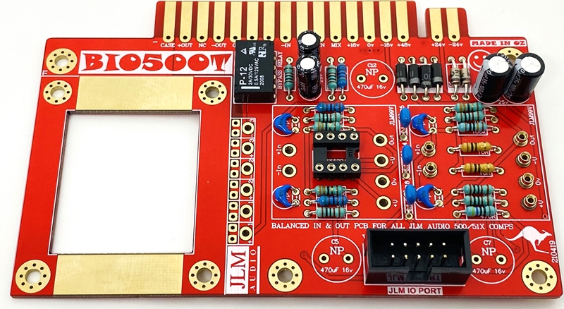
Fit and solder 100uF & 10uF Electro caps to PCB.
The 2 x 100uF caps are POLARIZED so must have their long positive leg fitted to + marked on PCB overlay.
The 2 x 10uF caps are NON polar types so can go in either way around on the PCB.
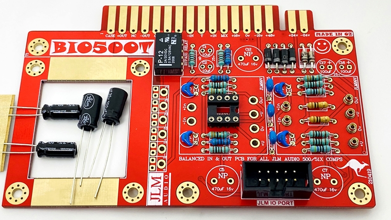

Fit and solder 470uF Electro caps to PCB.
The 3 x 470uF caps are NON polar types so can go in either way around on the PCB.

Fit and solder Gold Pins to PCB.
Some PCB batch have had holes a bit to small, if so click link below to see what to do https://www.jlmaudio.com/forum/viewtopic.php?p=4902#p4902
Fit Transformer to PCB
Fit NE5532A opamp in the correct POLARITY shown. 99v opamp can be fitted now or later. LA500 PCB is ready to go.

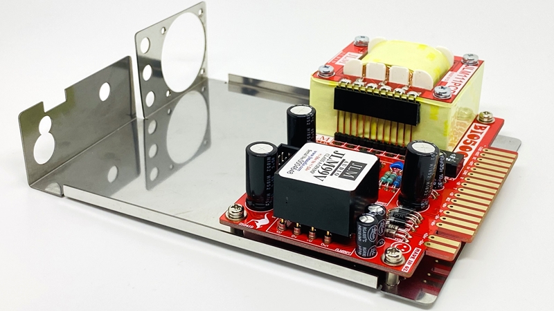
Fit BIO500T PCB to Bracket (LA500A bracket shown but PEQ500A has the same rear mounting standoff to screw the pcb too.)


Setup & Testing
The 500R 25turn trimpot is for setting unity gain and matching level between pairs of PEQ500A. With a 1kHz tone, turn off the power to the 500 rack with the PEQ500A in it. The PEQ500A will go into hard relay bypass. Set reference level like 0dBu (any level will do as long as you remember it) then power up the 500 rack and switch EQ to EQ out and adjust trimpot for same 0dBu. If doing a pair make sure they are set to the same frequencies as even in EQ off it affects level slightly.
If you would like to check everything is working then with music playing set high boost to full and step though the frequencies to make sure you can hear the boost working on all frequencies. Then press BW so shelf orange led lights and step though all frequencies. If shelf is not working then check you soldered the 2 solder pads together on the HI PCB. Even in shelf the BW with change the slope into the shelf. Do this for each boost and cut. Plugin doctor set to use hardware is a perfect way to check the frequencies and there match. But if you bought a pair of PEQ500A we would have matched everything so that will be near perfect.
