500 Tester Dual and single Build Thread
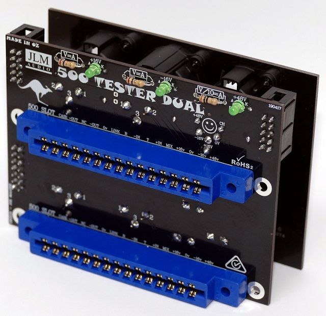
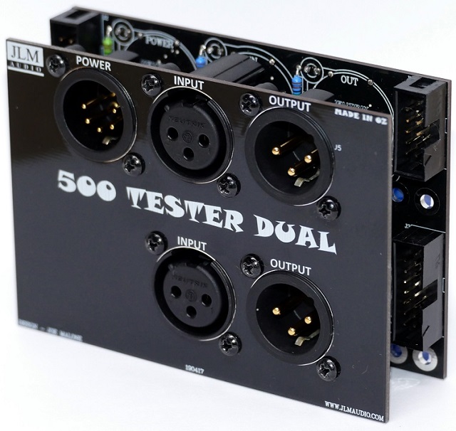
Dual 500 Tester build map at link below
http://jlmaudio.com/builds/maps/500Dual_Map.html
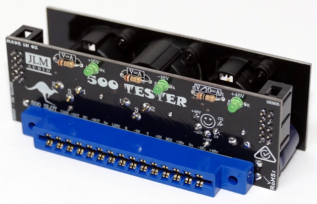
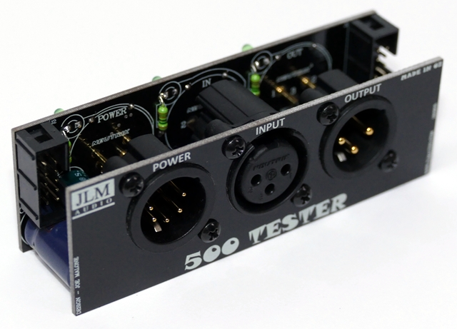
Single 500 Tester build map at link below
http://jlmaudio.com/builds/maps/500Single_Map.html
10-pin IDC headers are for linking multiple single or dual testers so only one power supply is needed
pin1,2 0v
pin 3,4 link pin 6 of edge connector
pin 5,6 +16v
pin 7,8 -16v
pin 9,10 +48v
14-pin IDC headers on the dual tester. The first 12 pins are half of Tascam DB25 pinout.
So 2 dual testers and be used to fit 500 modules into mixing console etc and easily ribbon cable out to D25 patchbays
Since all in and outs and power are on the 10 pin and 14 pin IDC connectors the XLRs and XLR front panel can be left off making the depth shorter for mounting inside non 500 consoles
pin 1 0v
pin 2 -in left channel
pin 3 +in left channel
pin4 0v
pin 5 -out left channel
pin 6 +out left channel
pin 7 0v
pin 8 -in right channel
pin 9 +in right channel
pin 10 0v
pin 11 -out right channel
pin 12 +out right channel
pin 13.14 0v not normally used
500 Tester Dual and Single Build Thread
Moderator: Joe Malone
- Joe Malone
- Site Admin
- Posts: 2080
- Joined: Wed Jan 24, 2007 11:35 pm
- Location: Brisbane, Australia
- Contact:
500 Tester Dual and Single Build Thread
Joe
JLM Audio
Capturing Audio without Injury
JLM Audio
Capturing Audio without Injury
Re: 500 Tester Dual and Single Build Thread
Thank you for the links, I will order soon 500 Tester Dual Build. Can you deliver to Europe? All September I will by at my parents Munich home
- Joe Malone
- Site Admin
- Posts: 2080
- Joined: Wed Jan 24, 2007 11:35 pm
- Location: Brisbane, Australia
- Contact:
Re: 500 Tester Dual and Single Build Thread
OK cool. Yes we send several parcels every day to Europe
Joe
JLM Audio
Capturing Audio without Injury
JLM Audio
Capturing Audio without Injury
Re: 500 Tester Dual and Single Build Thread
Hi Joe.
Received and tested with power.
The idc 10 pins is a power connector for other pcb´s?
The idc 14 pins is for input/output connections?
Can i have the diagram of that?
Thanks, Luís
Received and tested with power.
The idc 10 pins is a power connector for other pcb´s?
The idc 14 pins is for input/output connections?
Can i have the diagram of that?
Thanks, Luís
- Joe Malone
- Site Admin
- Posts: 2080
- Joined: Wed Jan 24, 2007 11:35 pm
- Location: Brisbane, Australia
- Contact:
Re: 500 Tester Dual and Single Build Thread
HI Luis
Added the info to first post above.
Joe
JLM Audio
Capturing Audio without Injury
JLM Audio
Capturing Audio without Injury
Re: 500 Tester Dual and Single Build Thread
Thanks Joe.
I sent to you one answer to your email.
- Joe Malone
- Site Admin
- Posts: 2080
- Joined: Wed Jan 24, 2007 11:35 pm
- Location: Brisbane, Australia
- Contact:
Re: 500 Tester Dual and Single Build Thread
I haven't seen your email?
Joe
JLM Audio
Capturing Audio without Injury
JLM Audio
Capturing Audio without Injury
Re: 500 Tester Dual and Single Build Thread
Nops....
Invoice for the pcb?
Information about the StereoBus pcb?
Luís Neves
Invoice for the pcb?
Information about the StereoBus pcb?
Luís Neves