Talkback Comp Build Thread
Moderator: Joe Malone
- Joe Malone
- Site Admin
- Posts: 2081
- Joined: Wed Jan 24, 2007 11:35 pm
- Location: Brisbane, Australia
- Contact:
Talkback Comp Build Thread
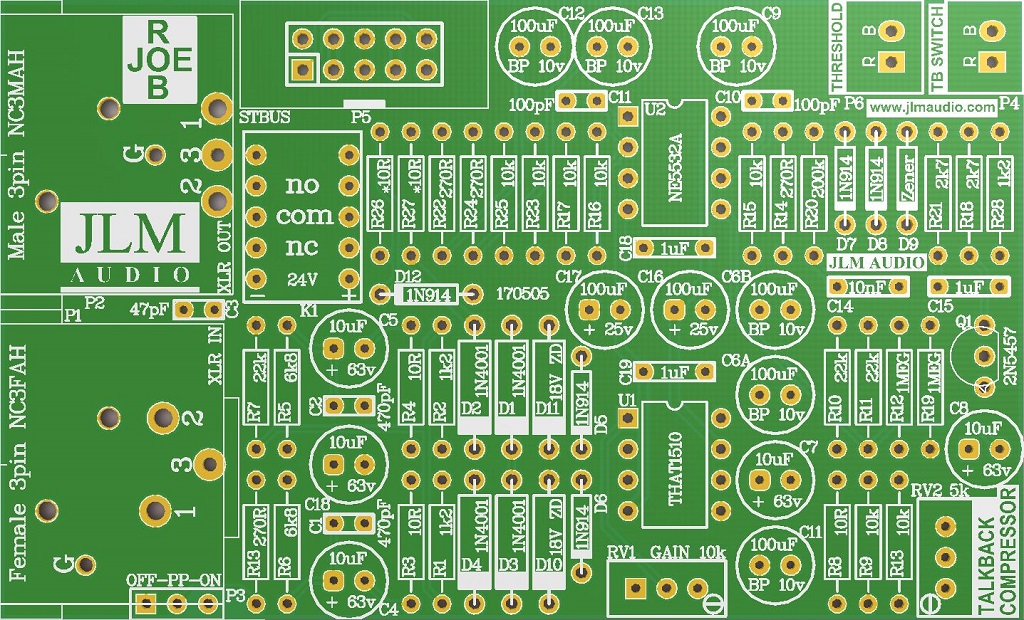
Fit all parts to pcb except one marked zener.
*10R are 10R if powering with 36vdc and have 18v zeners fitted to the PCB. Or if using any +/-12v to +/-18v with no 18v zeners fitted.
BOM for Talkback Comp at this link https://jlmaudio.com/TalkbackComp/BOM%20Talkback%20Comp%20170505.pdf
Use step by step build map at this link https://jlmaudio.com/builds/maps/talkbackcompmap.html
Either link zener with wire or short wires in threshold connector together to enable comp.
Turn both trim pots fully counterclockwise.
Power up with +/-18vdc
Send in 1k tone of -10dBu or less into input XLR so comp is not compressing at all.
Adjust VR2 clockwise until you drop the signal at the XLR output of the comp by 1dB.
Done.
You can now set RV1 for whatever mic gain you need.
The jumper beside the output XLR can be set for 18v phantom power or none.
Enjoy.
JLM STBUS 10pin output (Same as on AMP HEAD, Stereo IO kit etc)
Pin 1 Left +
Pin2 Left -
Pin 3 & 4 V+
Pin 5 & 6 0v
Pin 7 & 8 V-
Pin 9 Right -
Pin 10 Right +
Comp is mono so Left and Right BALIO & XLR Out are all linked together.
To stop crosstalk when talkback not being used Out + & - signals are shorted togehter by relay and comp locked fully down by relay.
Pressing Talkback button removes short on comp and output.
Joe
JLM Audio
Capturing Audio without Injury
JLM Audio
Capturing Audio without Injury
Re: Talkback Comp Build Thread
Hello Joe,
hope you‘re fine and had a good time at the AES.Seems some beautifull things are coming (I loved the 500 series VUPPM and the FX processor announcements!).
For the Talkback Comp:
1.:I‘d like to have full phantom power because I use condenser type microphones which need full +48vdc.Can I do it by classic feeding it via two 6K81 (matched) resistors to input pins 2 & 3?
I guess I can leave the +18vdc (jumper PP) disabled?
2.:For talkback use I‘d like to have a simple hpf on it,a first order fixed frequency (say 90 to 100Hz) would be o.k. for me.Possible?
3.:I see we can adjust threshold and mic gain.What‘s the output level,are we talking about line level around 0dBu?
4.:The TB-switch switches the relay,right? Would be easy to extend it to a jack for a footswitch,no?
Thank you in advance,
best regards from munich,
Udo.
- Joe Malone
- Site Admin
- Posts: 2081
- Joined: Wed Jan 24, 2007 11:35 pm
- Location: Brisbane, Australia
- Contact:
Re: Talkback Comp Build Thread
HI Udo great to hear from you. Yes several things coming soonkante1603 wrote:Hello Joe,
hope you‘re fine and had a good time at the AES. Seems some beautiful things are coming (I loved the 500 series VUPPM and the FX processor announcements!).
Talkback PCB has the 2 x 6k8 resistors already with 10uF smoothing cap. Just feed 48v into PP terminal for 48v phantom power. Do not fit any jumper to the other 2 pins.For the Talkback Comp:
1.:I‘d like to have full phantom power because I use condenser type microphones which need full +48vdc.Can I do it by classic feeding it via two 6K81 (matched) resistors to input pins 2 & 3?
I guess I can leave the +18vdc (jumper PP) disabled?
Change C4 & C5 from 10uF to 1.5uF each to HPF -3dB @ 90Hz. Must be 50v or more when using 48v phantom power.2.:For talkback use I‘d like to have a simple hpf on it,a first order fixed frequency (say 90 to 100Hz) would be o.k. for me.
Just add a resistor or pot across output XLR pin 2 & 3 to pad output. Output is driven by 2 x 270R resistor so it can be shorted by the relay.3.:I see we can adjust threshold and mic gain.What‘s the output level,are we talking about line level around 0dBu?
Yes will work but needs to be a fully floating TS jack as it cannot connect to 0v.4.:The TB-switch switches the relay,right? Would be easy to extend it to a jack for a footswitch,no?
Joe
JLM Audio
Capturing Audio without Injury
JLM Audio
Capturing Audio without Injury
Re: Talkback Comp Build Thread
Thank you very much Joe,
ordered some stuff some minutes ago.
Will you send the schematics (watermarked as always) with the Talkback Compressor kit?
Have a nice day,
best regards,
Udo.
ordered some stuff some minutes ago.
Will you send the schematics (watermarked as always) with the Talkback Compressor kit?
Have a nice day,
best regards,
Udo.
- Joe Malone
- Site Admin
- Posts: 2081
- Joined: Wed Jan 24, 2007 11:35 pm
- Location: Brisbane, Australia
- Contact:
Re: Talkback Comp Build Thread
HI Udo Yes I will send you the schematic now so you can study it before the kit arrives.kante1603 wrote:Thank you very much Joe,
ordered some stuff some minutes ago.
Will you send the schematics (watermarked as always) with the Talkback Compressor kit?
Have a nice day,
best regards,
Udo.
Joe
JLM Audio
Capturing Audio without Injury
JLM Audio
Capturing Audio without Injury
Re: Talkback Comp Build Thread
Thanks a lot Joe,
looking forward to receive the schematics,will definetely make things clearer for me.
Best regards,
Udo.
looking forward to receive the schematics,will definetely make things clearer for me.
Best regards,
Udo.
Re: Talkback Comp Build Thread
Hi Joe,
thank you for the schematics!
So D9 (Zener) can be omitted,yes?
It‘s also not in the BOM.
Shorting it out enables the compressor whether by closing/switching the threshold connector or directly by wire.
If we don‘t need the comp. we just leave it open (meaning omit D9)?
Can we bring the gain pot to a front panel? If yes which taper is prefered?
Thank you in advance,
Udo.
- Joe Malone
- Site Admin
- Posts: 2081
- Joined: Wed Jan 24, 2007 11:35 pm
- Location: Brisbane, Australia
- Contact:
Re: Talkback Comp Build Thread
D9 is optional to raise the threshold level. You can use a series string of diodes and zeners to have switchable threshold levels.kante1603 wrote:Hi Joe,
thank you for the schematics!
So D9 (Zener) can be omitted,yes?
It‘s also not in the BOM.
Shorting it out enables the compressor whether by closing/switching the threshold connector or directly by wire.
If we don‘t need the comp. we just leave it open (meaning omit D9)?
Can we bring the gain pot to a front panel? If yes which taper is prefered?
Thank you in advance,
Udo.
Normally you would just short the threshold pins together to enable the comp
Gain pot for best control on front panel use is a 10k rev log pot.
If using for talkback you will be amazed at how set and forget it can be and work with constant output no matter what input level.
Joe
JLM Audio
Capturing Audio without Injury
JLM Audio
Capturing Audio without Injury
Re: Talkback Comp Build Thread
Hi Joe,
if I‘m right then first things first:HAPPY BIRTHDAY!!!
(I‘m in the same „league“)
Have built it today,looking good so far.
Am I right that the output is quite hot?
Can you tell us a rough gain range for Rgain (from ccw to cw) with the compressor disabeled?
The compressor bias went well,although I found a more usefull starting point at about -15dBu on my generator to set the -1dB point.
For now I only have a generator (close to 0 ohms output imp.) and a receiver (100k on input),so measured values will change a bit I think.
Will do a real world test in the studio next week with some microphones (50 to 200ohms) into a DAW interface or active speakers (10k to 20k inputs) and report back.
Looks promising!
Best regards,
Udo.
Re: Talkback Comp Build Thread
Hello Joe,
The package arrived the other day.
Thank you very much.
If possible, could you send me a schematic for the Talkback Compressor kit and the Dsub 4 kit?
Best regards,
The package arrived the other day.
Thank you very much.
If possible, could you send me a schematic for the Talkback Compressor kit and the Dsub 4 kit?
Best regards,
Last edited by Norikazu on Tue Apr 02, 2019 4:01 pm, edited 1 time in total.
- Joe Malone
- Site Admin
- Posts: 2081
- Joined: Wed Jan 24, 2007 11:35 pm
- Location: Brisbane, Australia
- Contact:
Re: Talkback Comp Build Thread
HI NorikazuNorikazu wrote:Hello Joe,
The package arrived the other day.
Thank you very much.
If possible, could you send me a schematic for the Talkback Compressor kit and the Dsub 4 kit?
Yes send an email to me at joe@jlmaudio.com and I will send it when I am on the workshop computer
Joe
JLM Audio
Capturing Audio without Injury
JLM Audio
Capturing Audio without Injury
Re: Talkback Comp Build Thread
Is there anyway to add very simple GR metering on this? Doesn't need to be accurate. I've VU buffer pcb's handy if that simplify things?
thanks
Paul
thanks
Paul
- Joe Malone
- Site Admin
- Posts: 2081
- Joined: Wed Jan 24, 2007 11:35 pm
- Location: Brisbane, Australia
- Contact:
Re: Talkback Comp Build Thread
A high brightness led across the threshold plug wires will give a compression threshold led. A uA meter across the same wires may be able to be calibrated to be like a SSL GR meter but haven't experimented with this.mrclunk wrote:Is there anyway to add very simple GR metering on this? Doesn't need to be accurate. I've VU buffer pcb's handy if that simplify things?
thanks
Paul
Joe
JLM Audio
Capturing Audio without Injury
JLM Audio
Capturing Audio without Injury
Re: Talkback Comp Build Thread
So i couldn't find a high brightness LED that would work so i made a little TL072 buffer circuit to drive an GR LED. Works well.
Next question..
How would i go about powering an Electret (TB) mic with this circuit?
Can i just remove one of the 6K8 resistors and put a 9V zener across the PP to ON jumper terminals.
My PSU Desk psu is +/- 17VDC
Think that should work...
thanks
paul
Next question..
How would i go about powering an Electret (TB) mic with this circuit?
Can i just remove one of the 6K8 resistors and put a 9V zener across the PP to ON jumper terminals.
My PSU Desk psu is +/- 17VDC
Think that should work...
thanks
paul
- Joe Malone
- Site Admin
- Posts: 2081
- Joined: Wed Jan 24, 2007 11:35 pm
- Location: Brisbane, Australia
- Contact:
Re: Talkback Comp Build Thread
HI Paul Sorry missed this post. Do you have a link to the Electret mic you are going to use and I will draw up the best way to use it.mrclunk wrote:So i couldn't find a high brightness LED that would work so i made a little TL072 buffer circuit to drive an GR LED. Works well.
Next question..
How would i go about powering an Electret (TB) mic with this circuit?
Can i just remove one of the 6K8 resistors and put a 9V zener across the PP to ON jumper terminals.
My PSU Desk psu is +/- 17VDC
Think that should work...
thanks
paul
Joe
JLM Audio
Capturing Audio without Injury
JLM Audio
Capturing Audio without Injury