
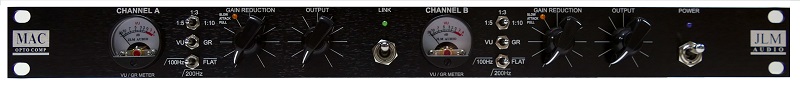
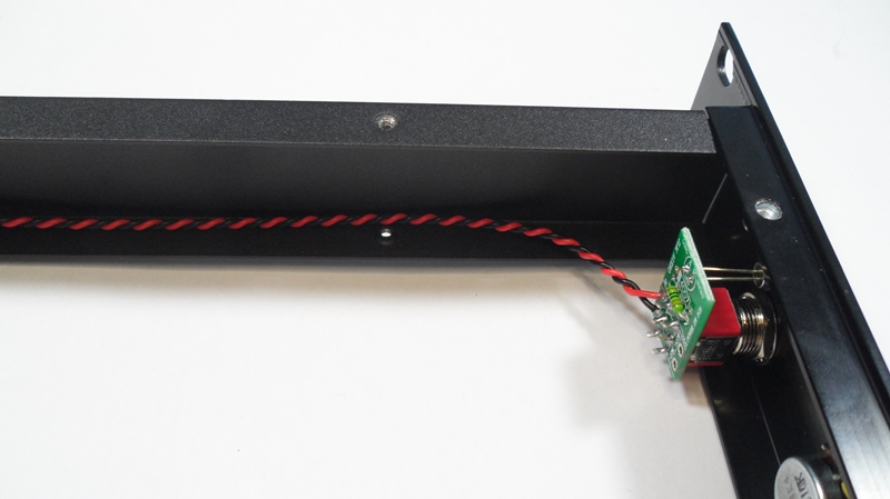
Comp has new pull switches for threshold to activate the slow attack feature with orange led on front panel
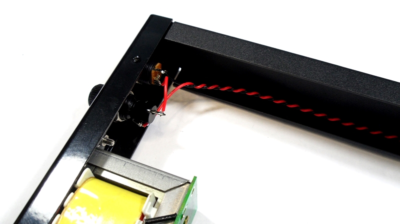
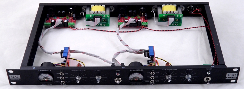
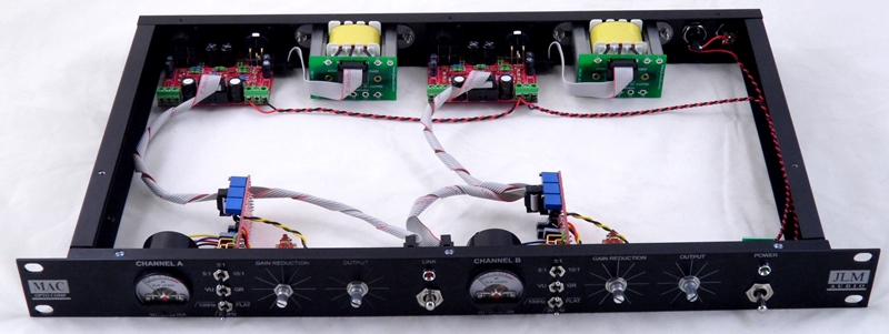
Final led colours are red for link and green for power on. (Not the blue and green as shown)
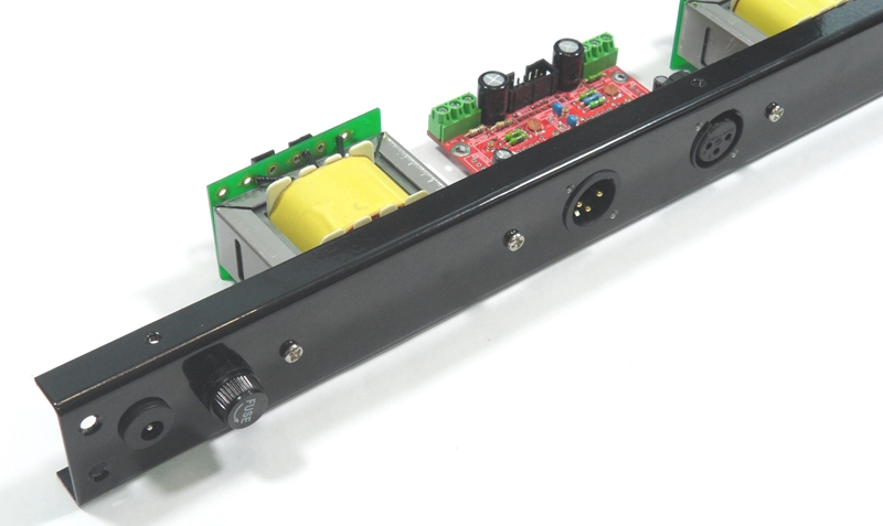
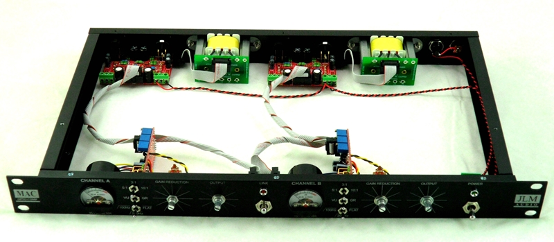
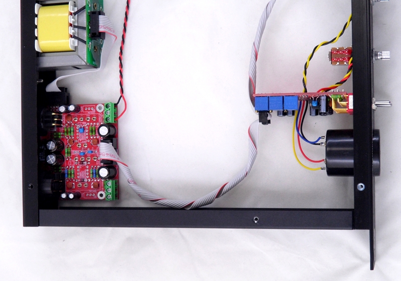
MAC RACK KIT Build Thread using LA500SCv3 & LA500POTv4 kits like our LA500A comps so has very little wiring to do
MAC rack kit uses 2 x dINgO kits
dINgO schematic at the link below
http://www.jlmaudio.com/dingo/dINgOv4 f ... ematic.pdf
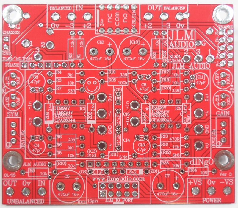
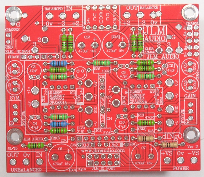
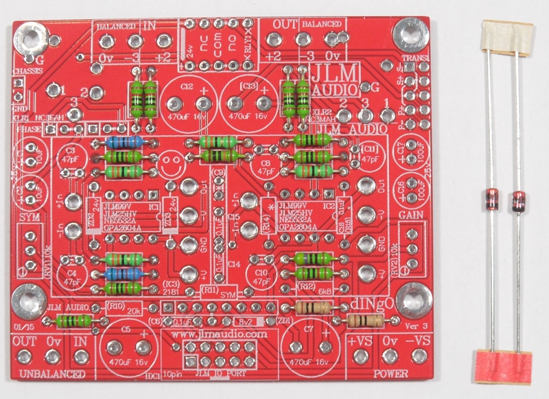
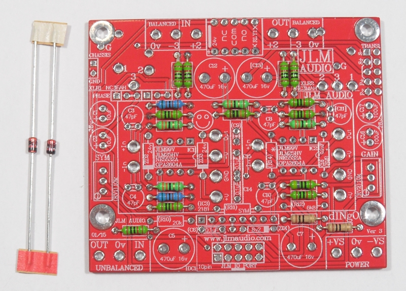
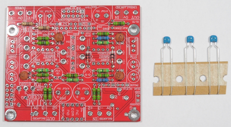
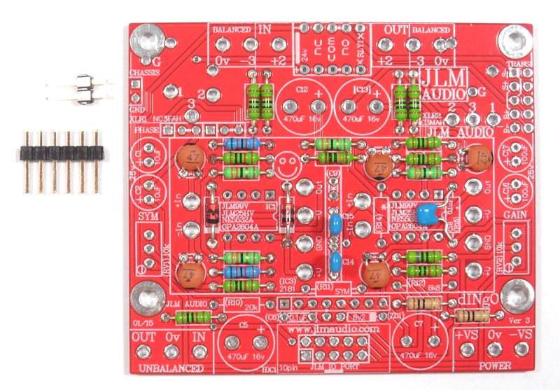
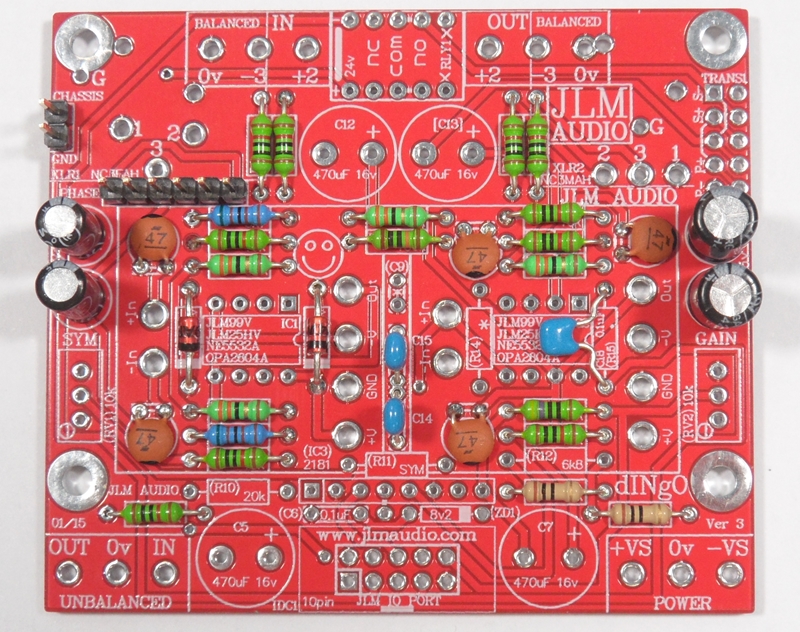
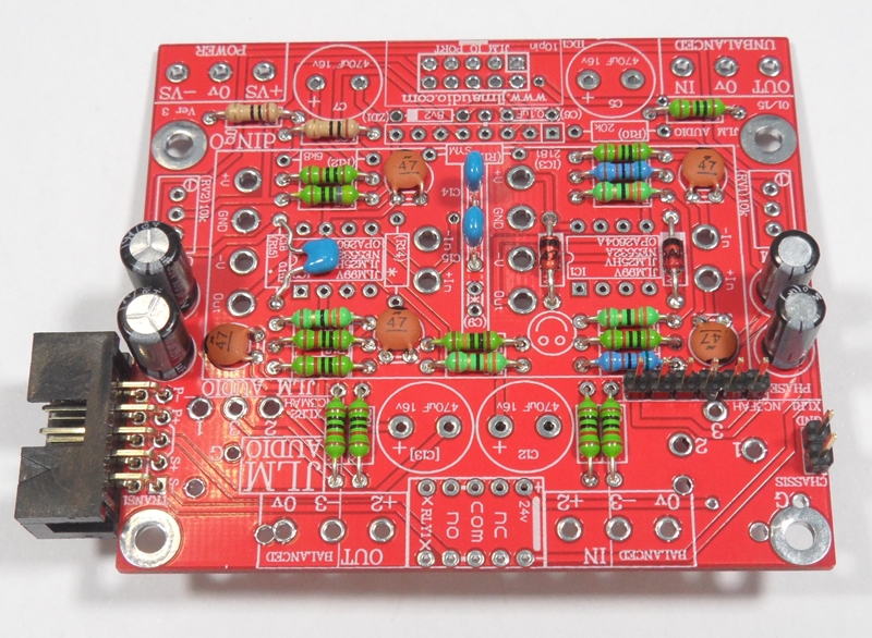
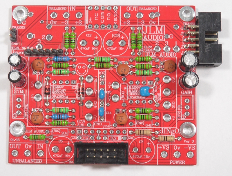
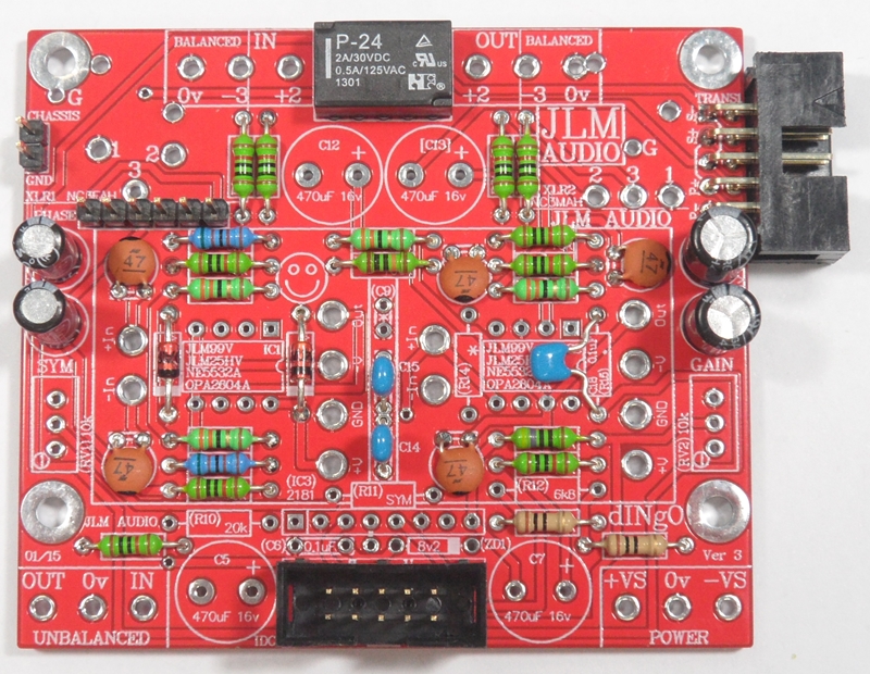
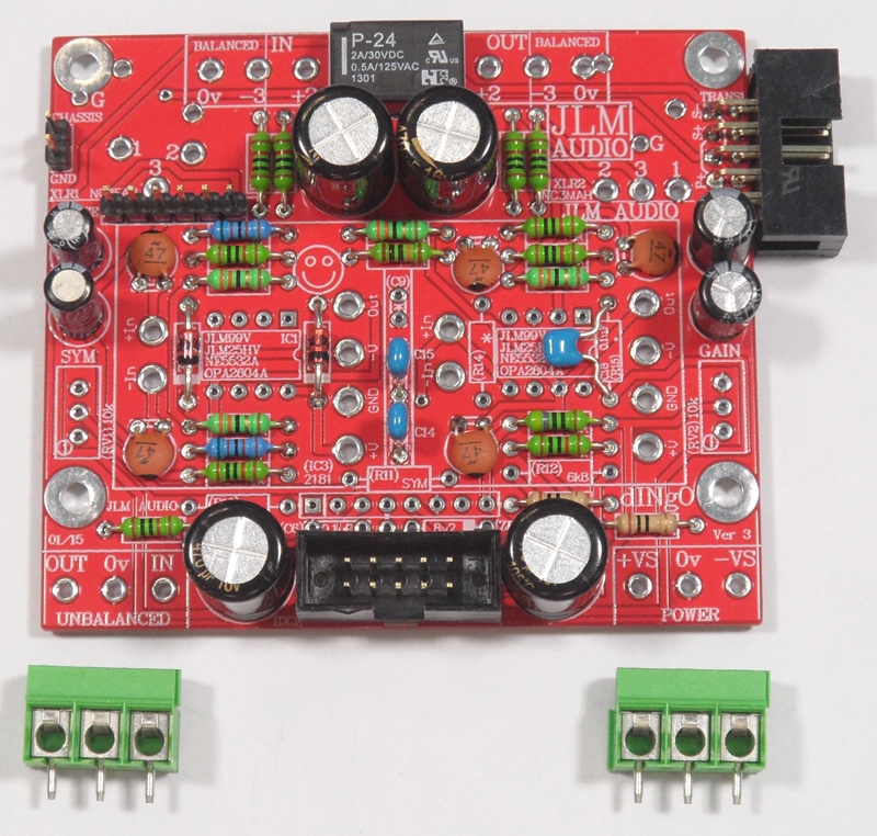
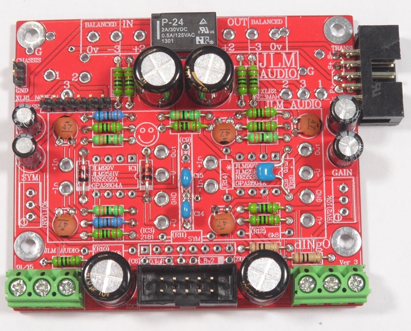
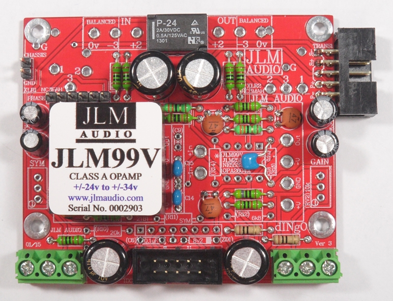
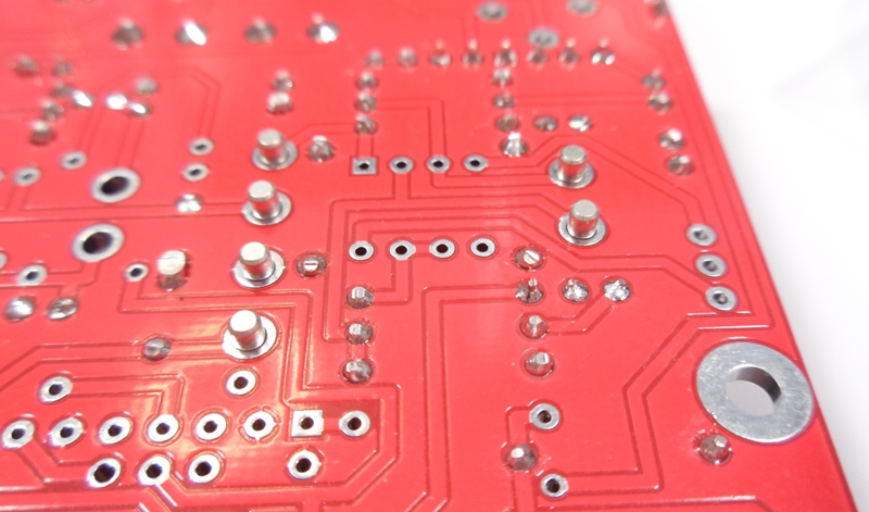
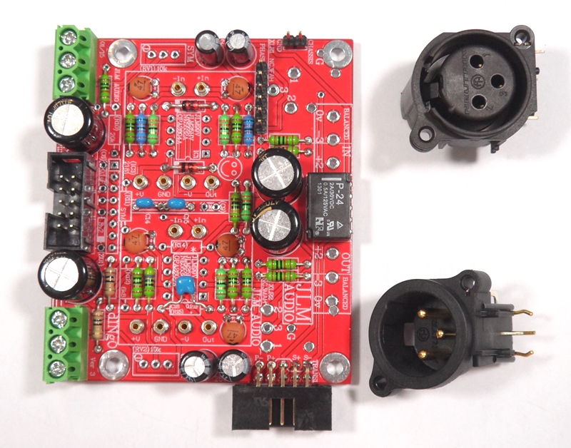
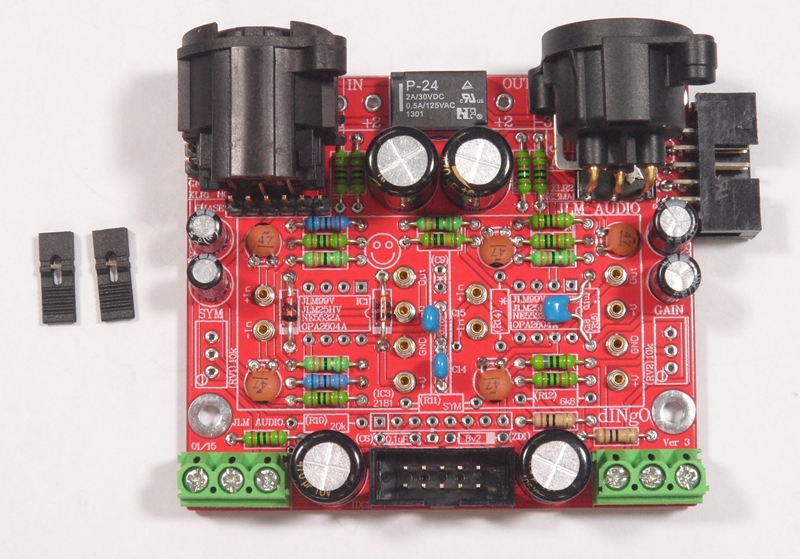
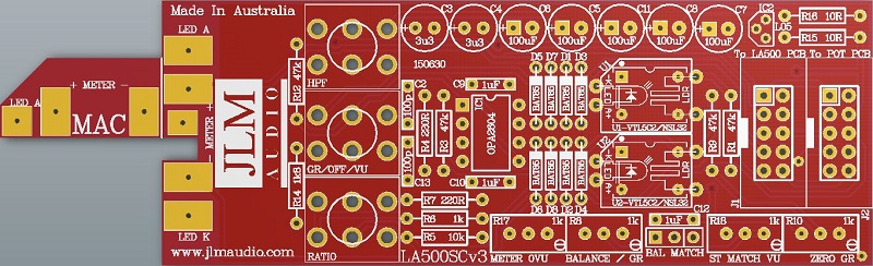
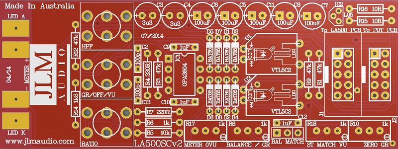
Blank dINgO PCB with full overlay shown (All parts numbers in () or [] brackets are not used with JLM99v opamps)
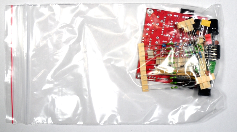
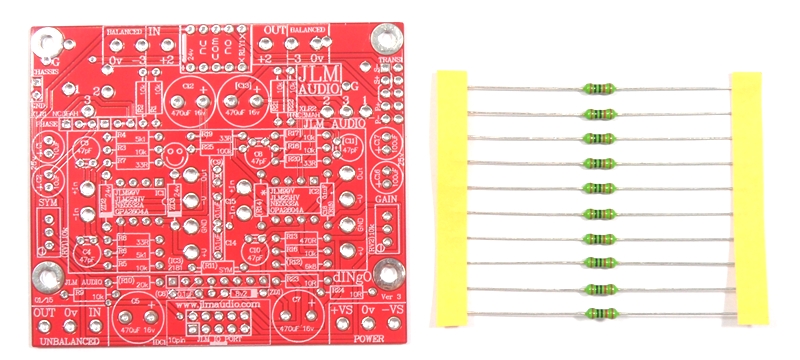
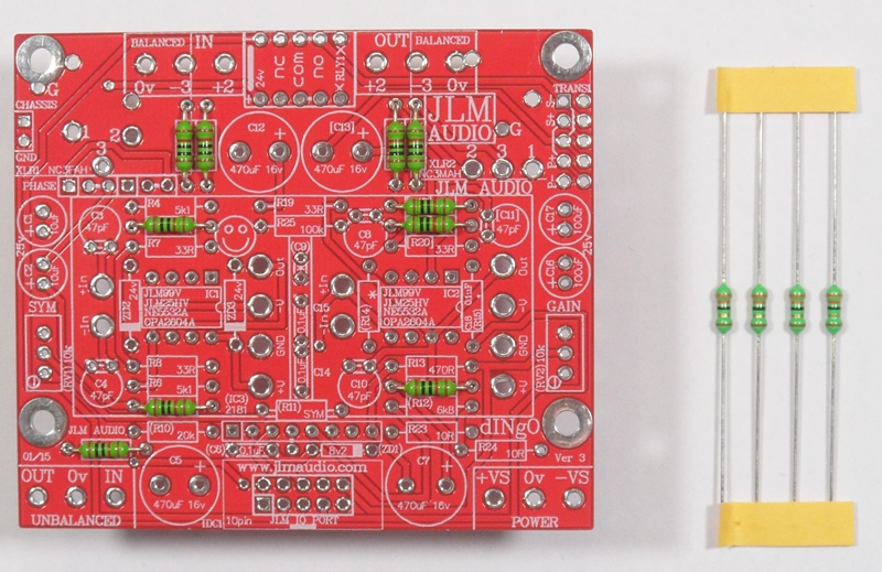
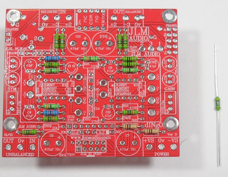
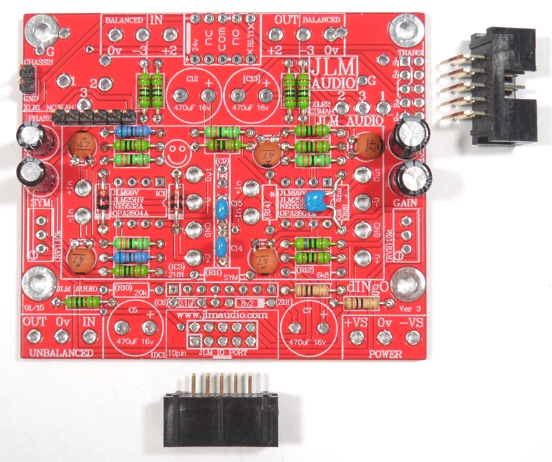
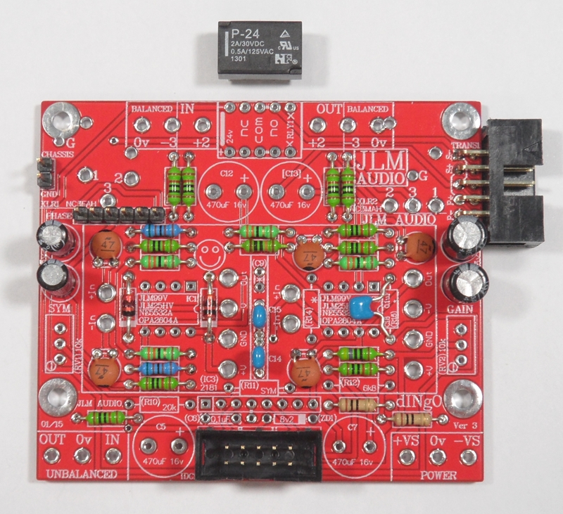
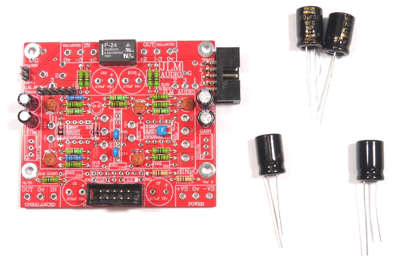
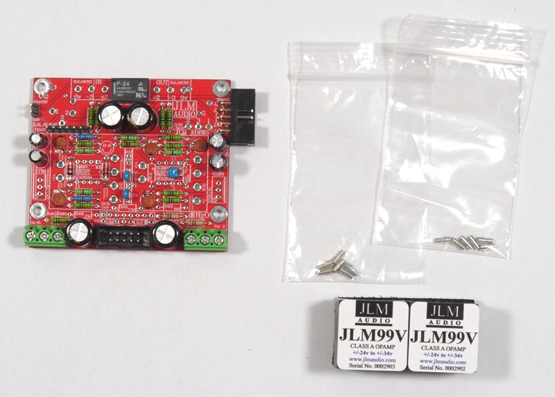
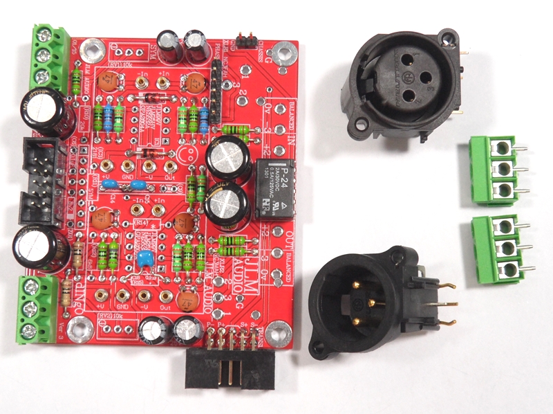
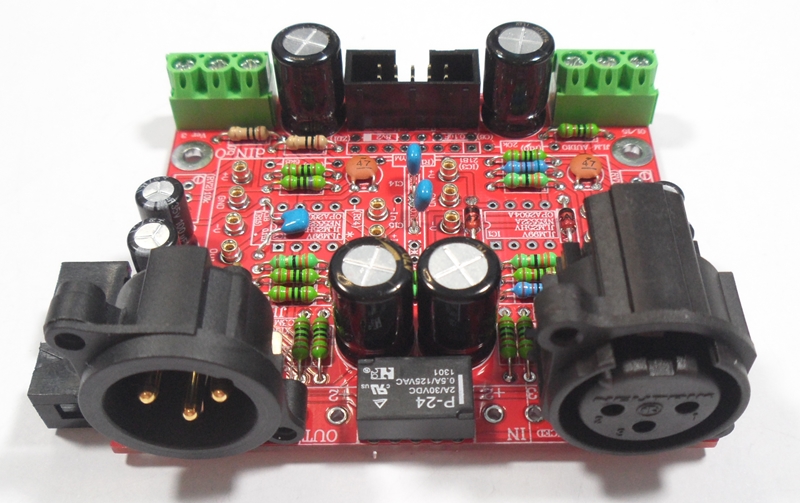
dINgO kit with all small parts shown. There will also be PCB XLR's in MAC rack kit.
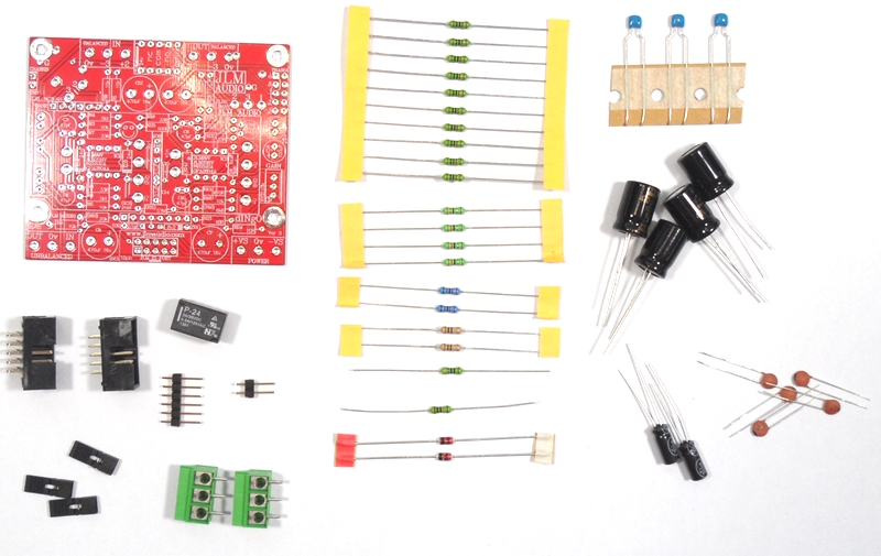
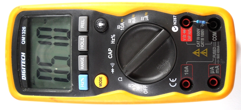
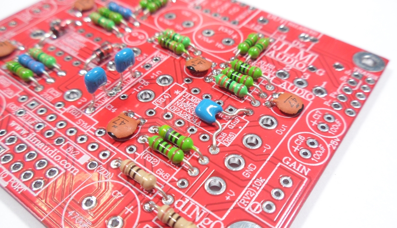
If you are not 100% with resistor colour codes use a multimeter to check values as you place the resistors
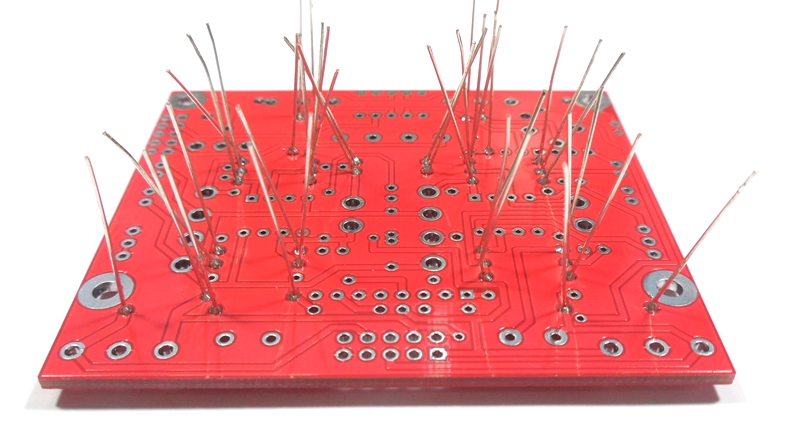
Fit all resistors at once bending the legs sightly outwards to hold them in place. This helps to make sure no resistors are put in the wrong position.
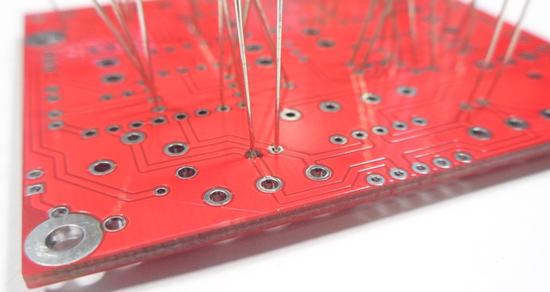
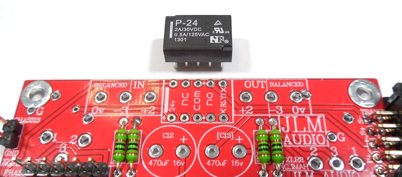
Start with fitting of the 10k resistors into the PCB and bend the legs slightly outwards so they do not fall out when PCB is turned over.
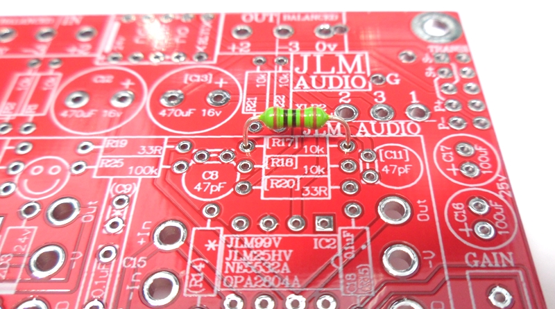
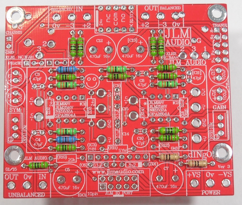
Fitting of the 33R resistors
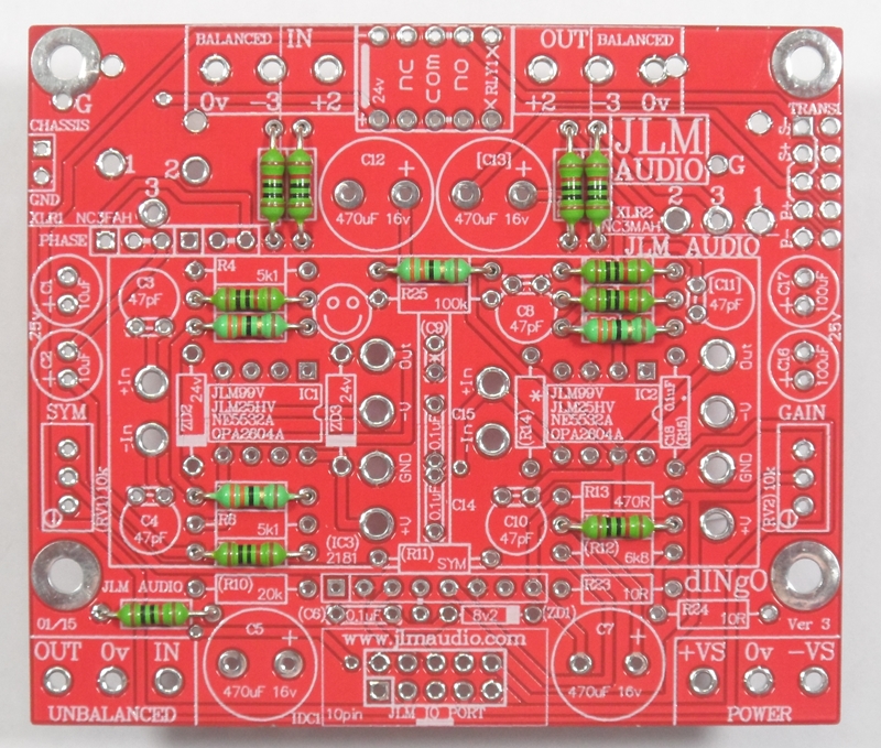
Fitting of the 5k1 resistors

Fitting of the 10R resistors
Fitting of the 470R resistor
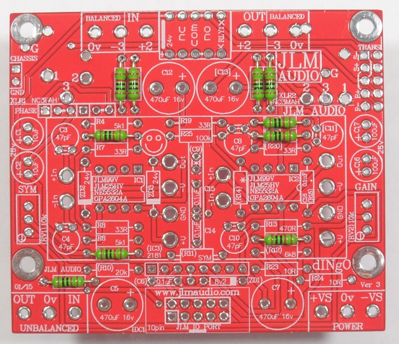
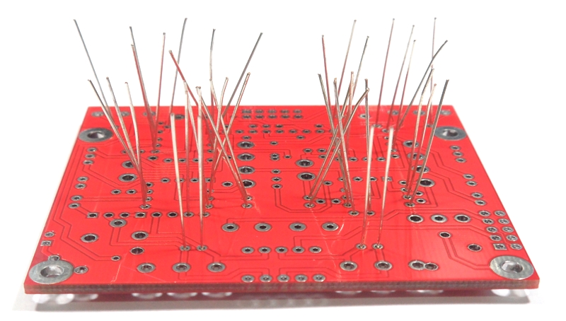
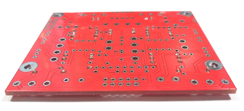
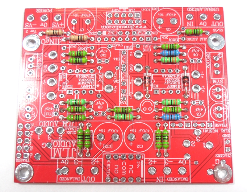
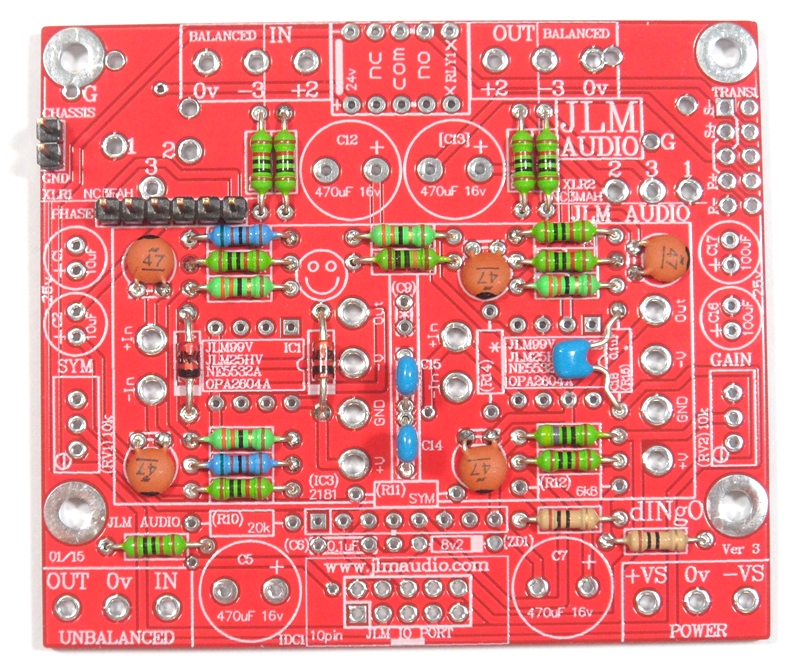
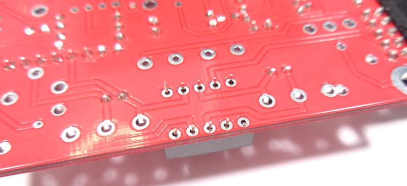
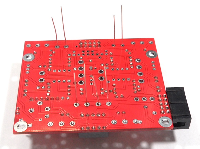
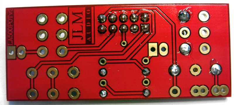
Turn over PCB on flat surface and solder and trim all resistors legs
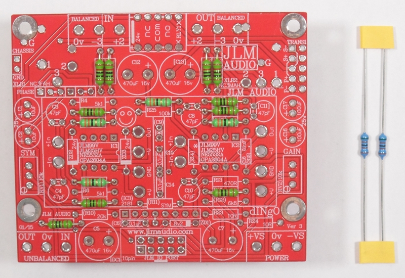
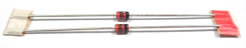
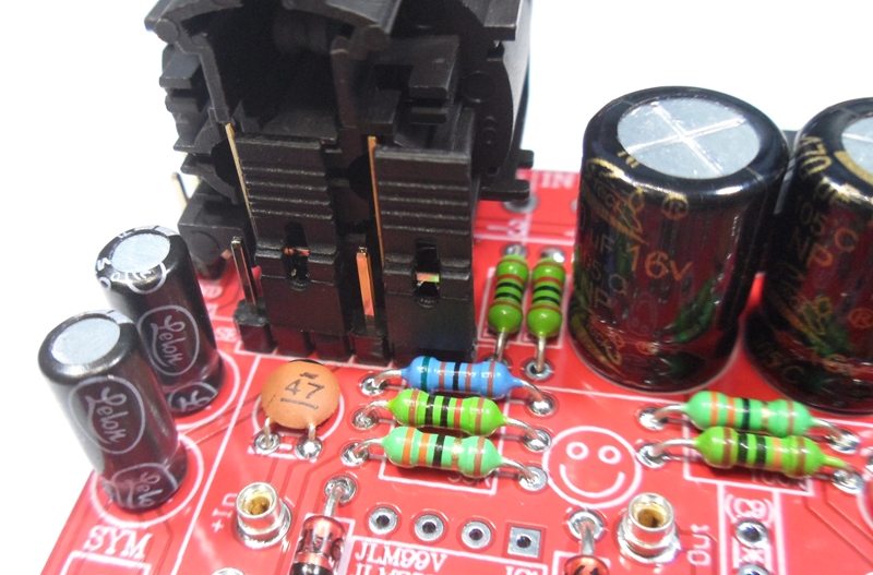
Fit the two 24v zener diodes with stripes lined up with stripe on PCB and solder and trim legs

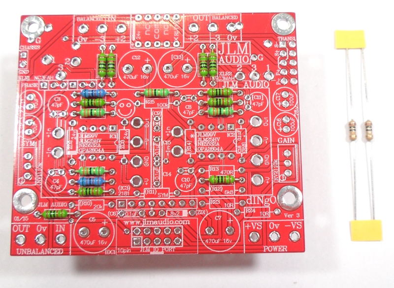
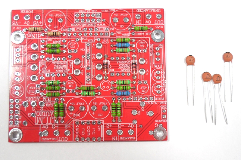
Fit the 4 x 47pF ceramic caps folded flat to the PCB and solder and trim legs

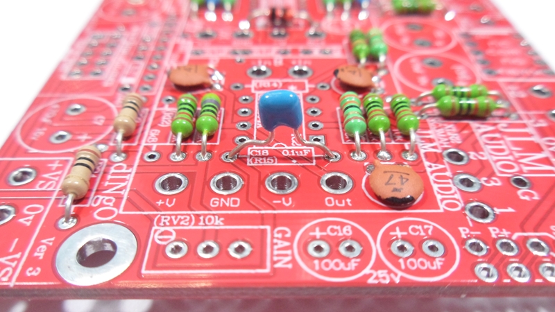
Fit the 3 x 100nF mono caps with one folded flat to the PCB and solder and trim legs
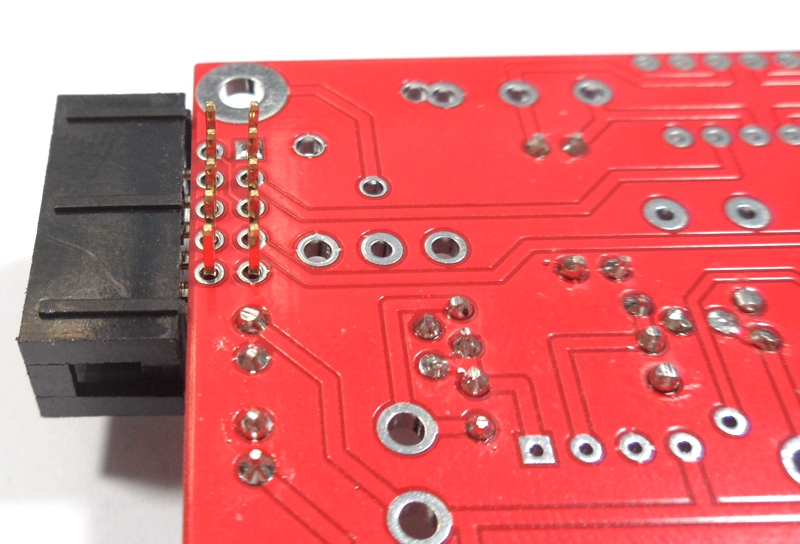
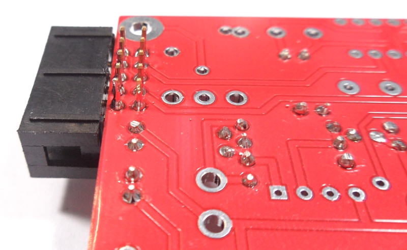
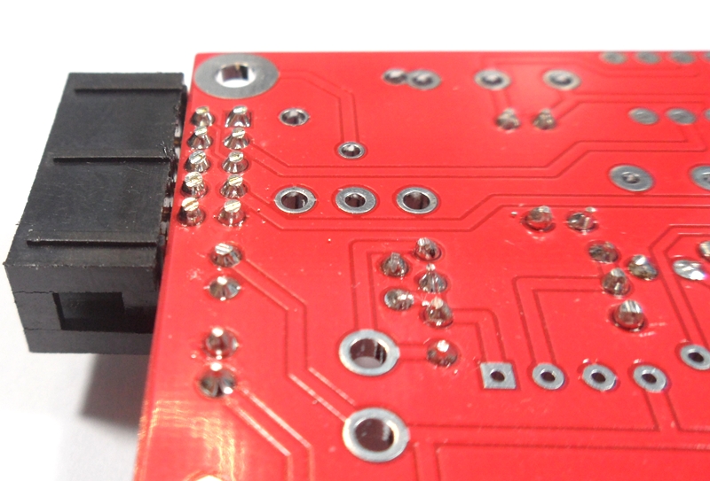
Fit the 2 x gold pin sets to the PCB and solder. Best to solder one pin on each and check if they are sitting straight before soldering all pins.

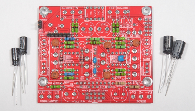
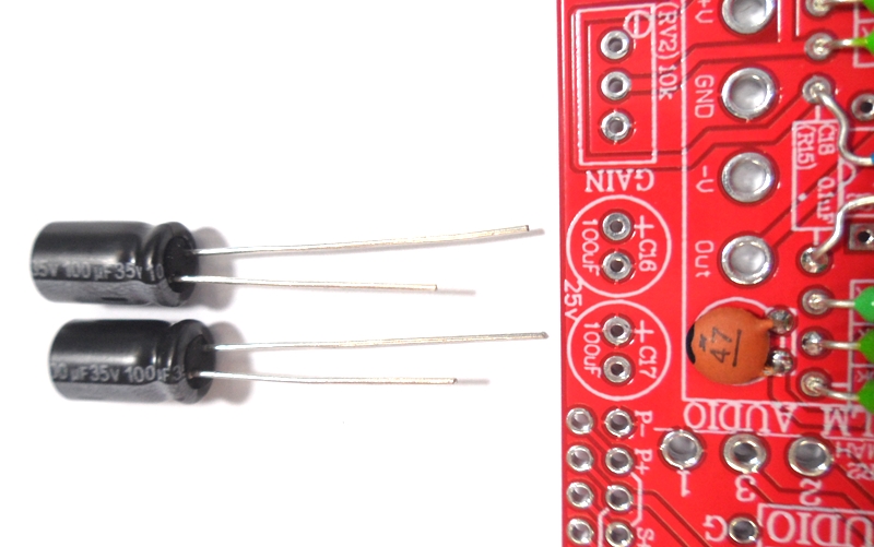
Fit the 2 x 10uF & 2 x 100uF electro caps the check way around to the PCB and solder and trim legs. (+leg is the long leg of the cap)
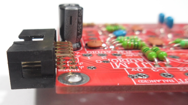
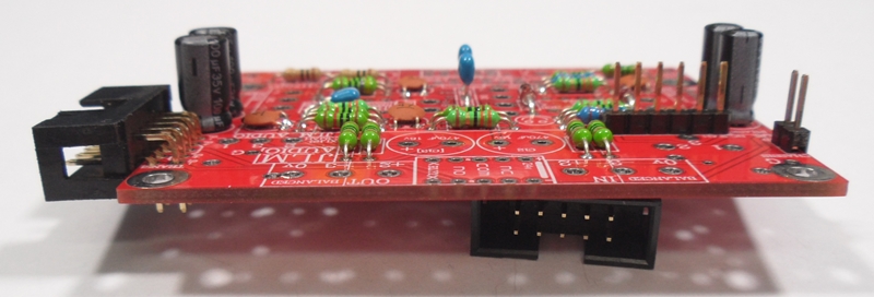
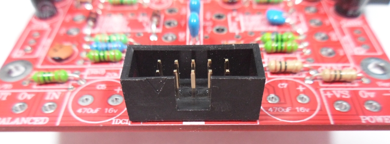
Fit 2 x 10pin IDC headers to the PCB and solder and trim legs.

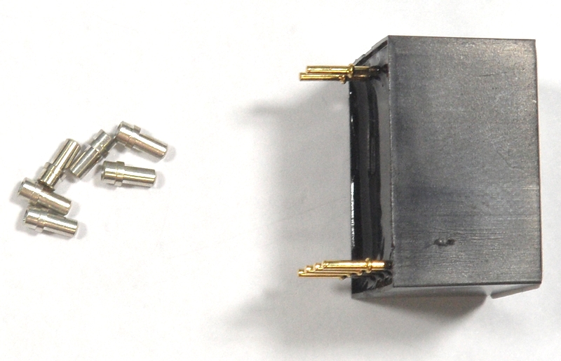
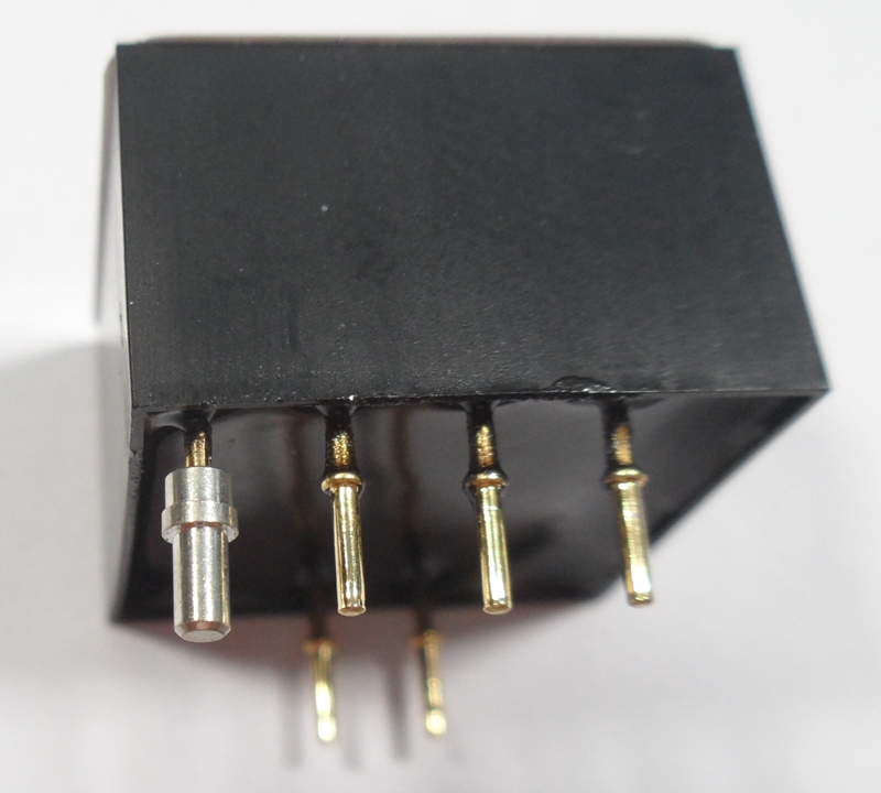
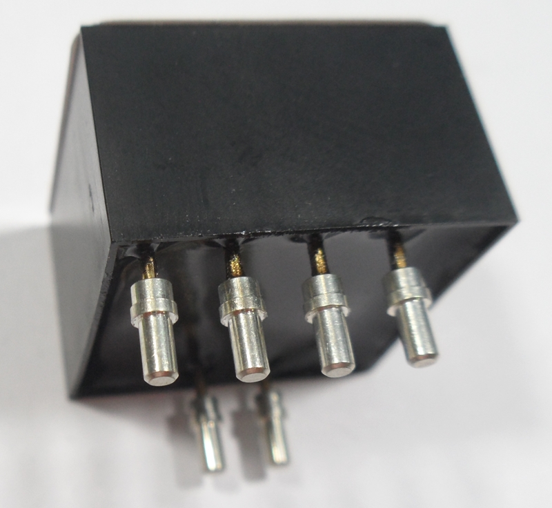
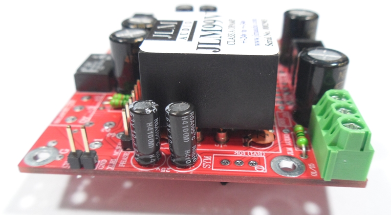
Fit 24v relay to the PCB and solder and trim legs. Make sure stripe on relay matches stripe on PCB
Fit 4 x 470uF 16v Non Polar electro caps to the PCB and solder and trim legs. These are Non Polar so can be fitted either way around.
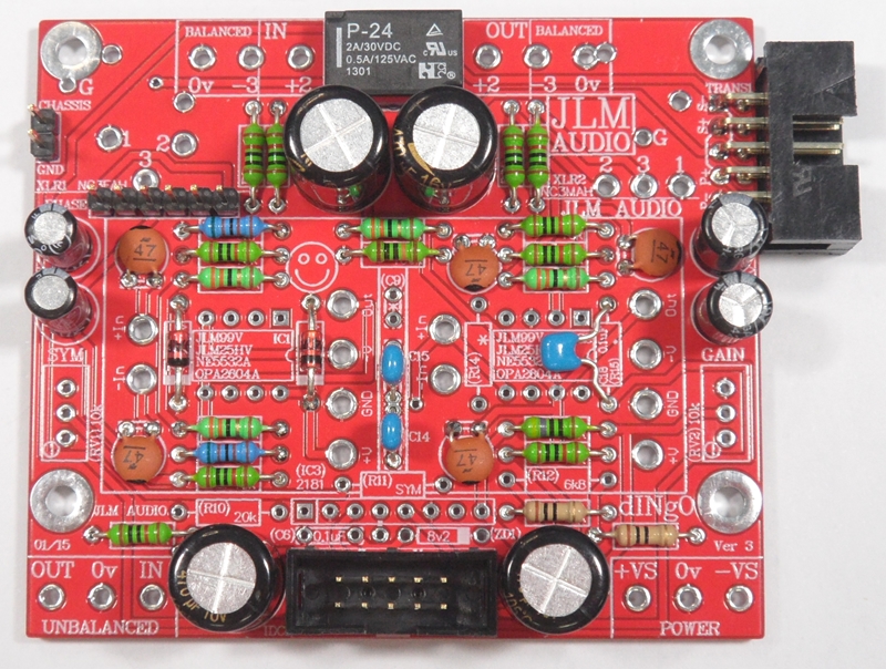
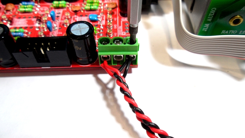
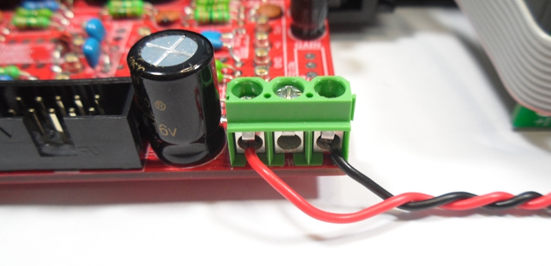
Fit 2 x 3way terminal block to the PCB and solder and trim legs.
Fit 12 pins for the 2 x JLM99v opamps to the PCB and solder and trim legs.

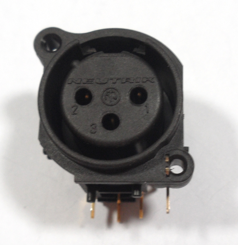
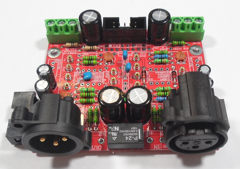
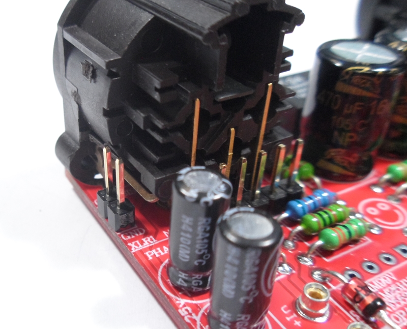
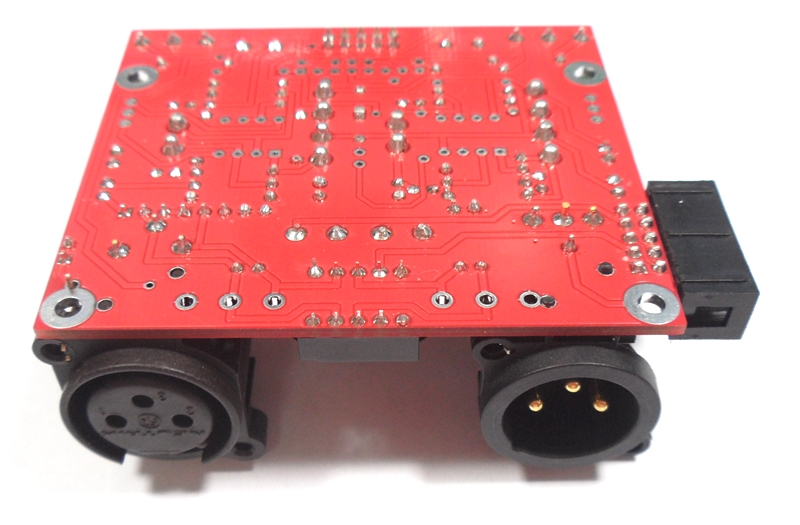
Fit Male and Female XLR to the PCB and solder and trim legs. There maybe left over 3 way terminal blocks in the kit.
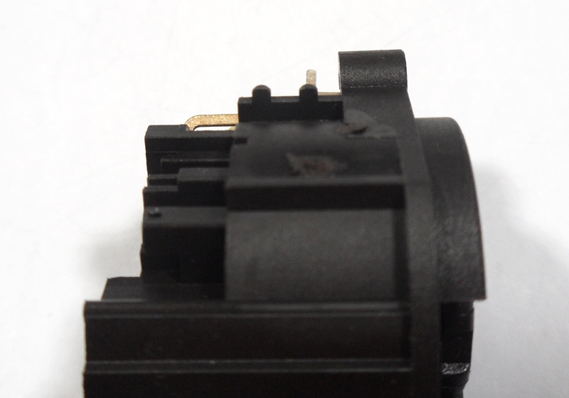
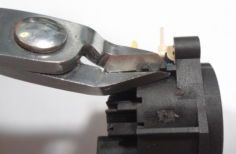
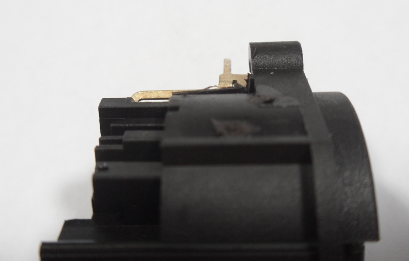
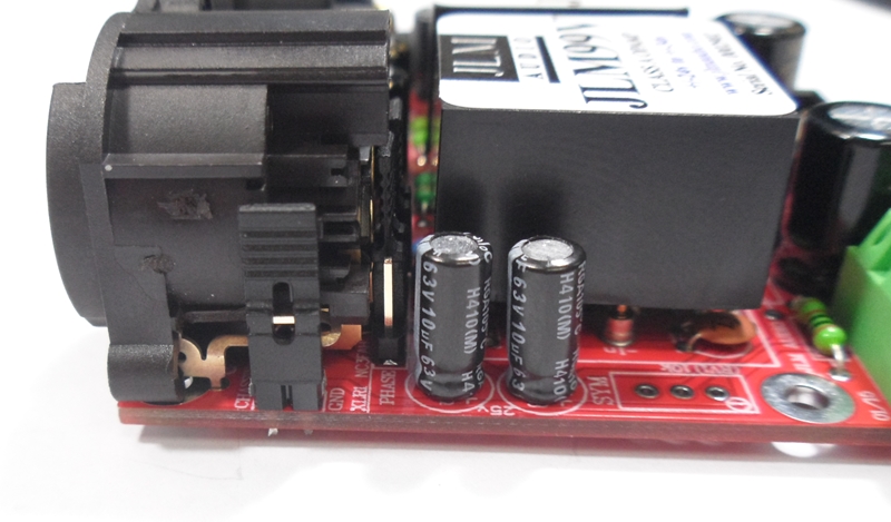
Trim side of Female XLR with sidecutters as shown
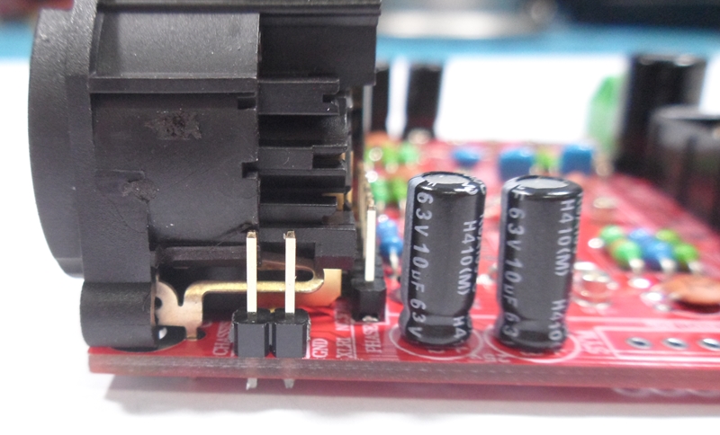
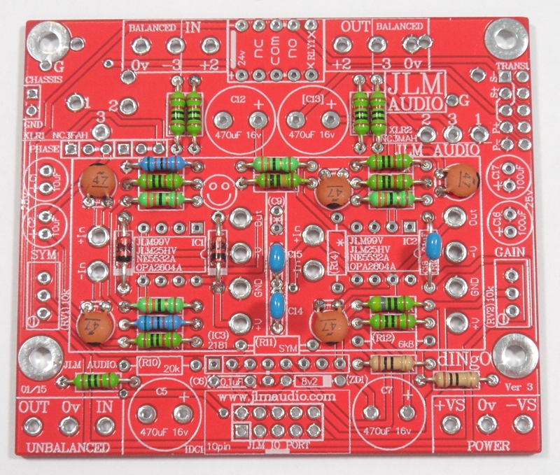
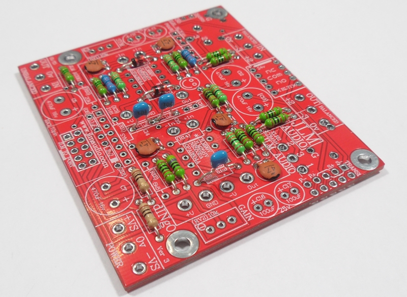
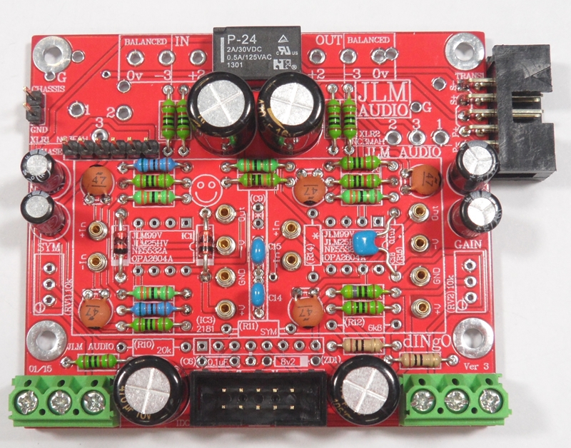
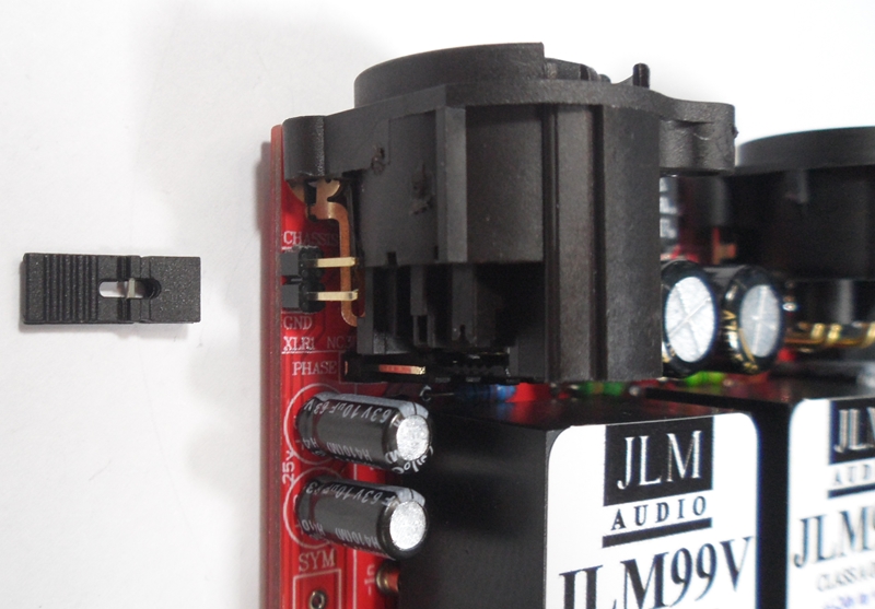
Fit input polarity jumpers as shown for correct phase.
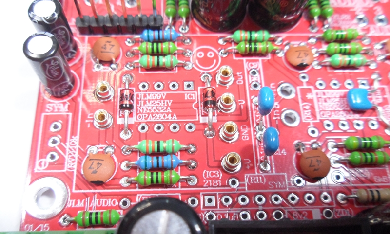
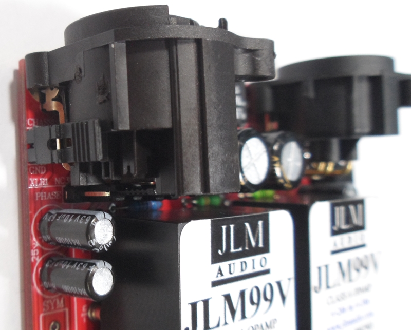
Fit 2 x JLM99v opamps to the 12 sockets on the PCB

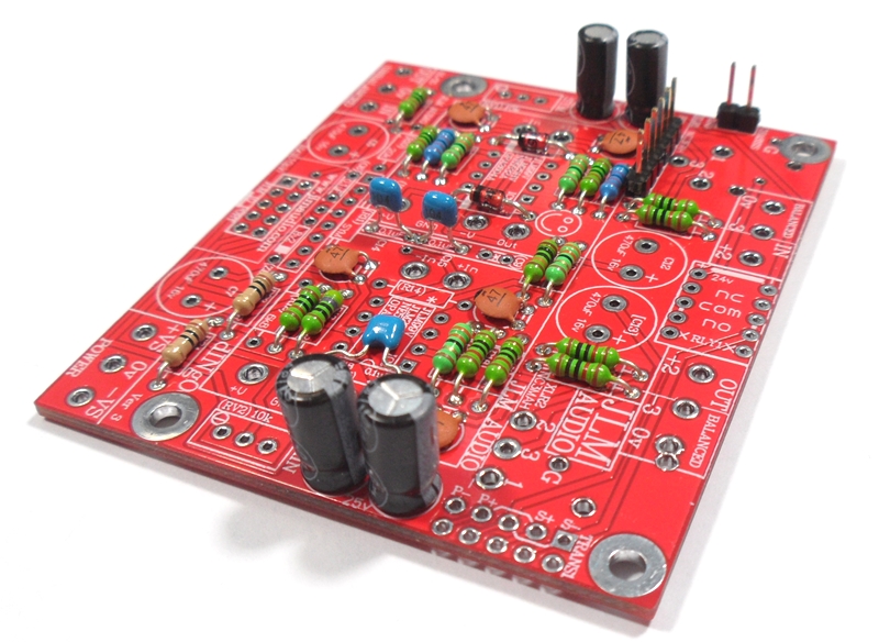
Fit ground link jumper beside XLR. Thid dINgO is built and ready. Build second dINgO and then move on to MAC PCB kits.

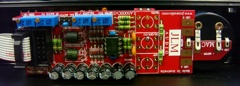
THE LA500SCv3 PCB is the MAC PCB but with no hand wiring and slow attack parts added
NEW LA500SCv3 PCB has extra MAC part so no meter wiring is needed in MAC rack kits
and some extra holes under U1 & U2 optos which are not used for now
MAC schematic at the link below is the same.
http://www.jlmaudio.com/MAC/MACSCH.pdf
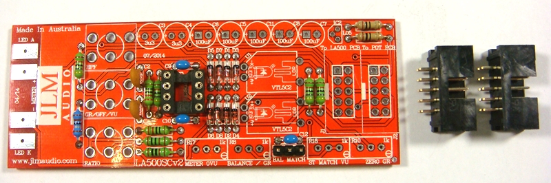
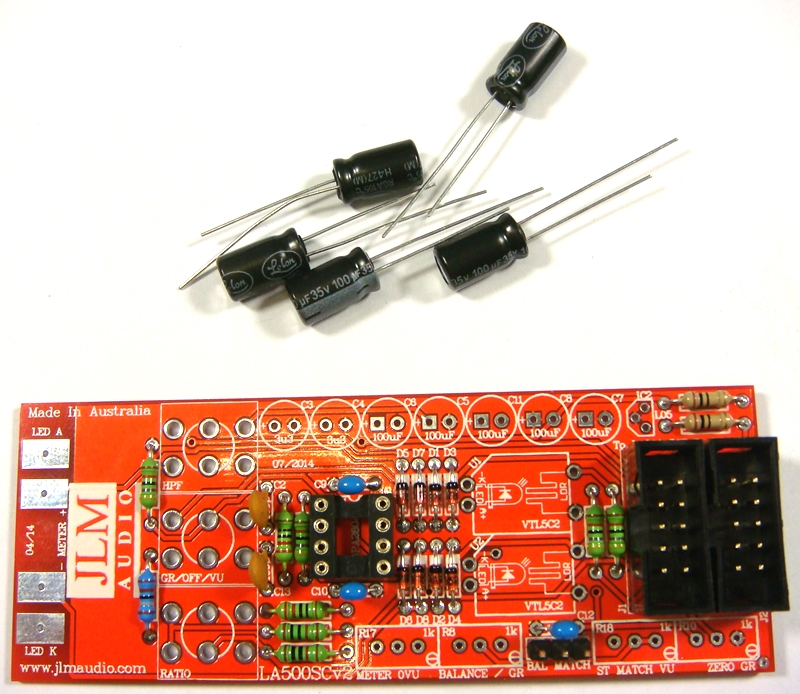
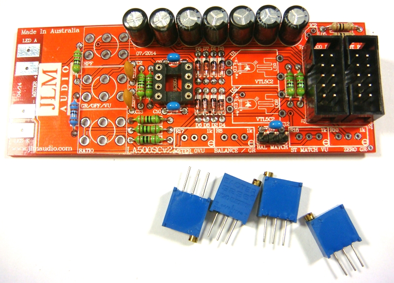
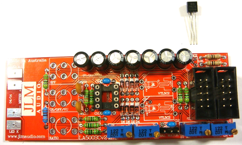
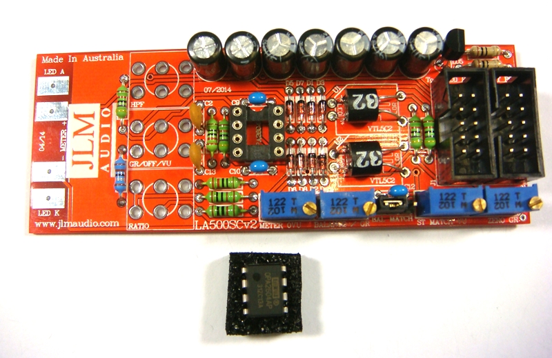
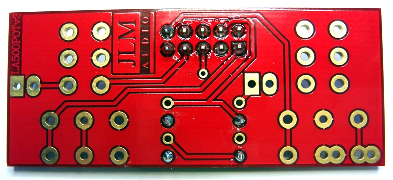
LA500SCv3 PCB parts kit
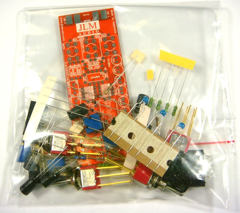
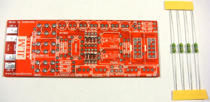
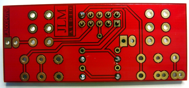
LA500SCv2 PCB. PCB overlay has all values and there are no options.
so PCB can be assembled directly from overlay.
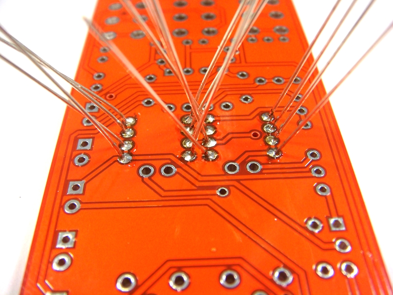
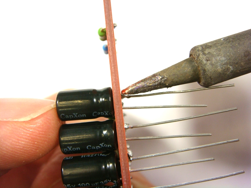
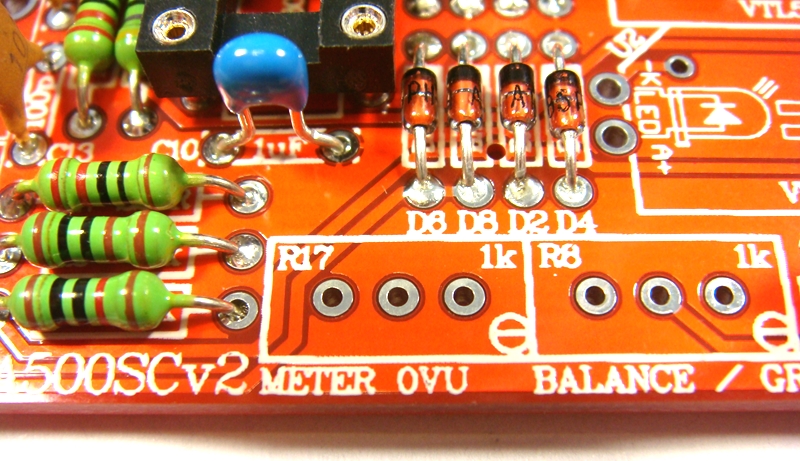
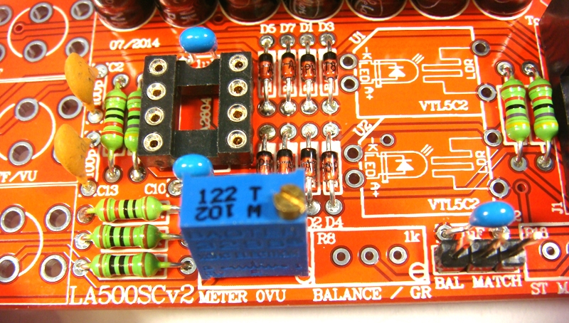
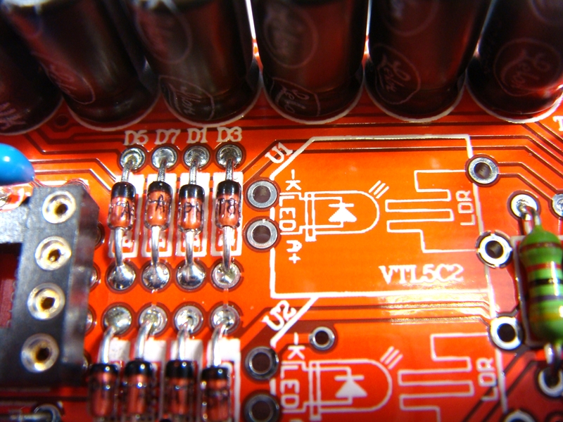
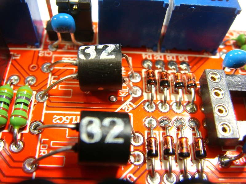
Fit all 8 x BAT85 diodes with there Cathode POLARIZED black stripe matching the white stripe on the MAC PCB overlay
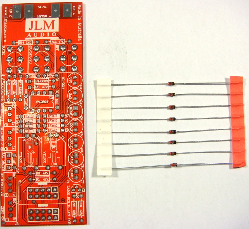

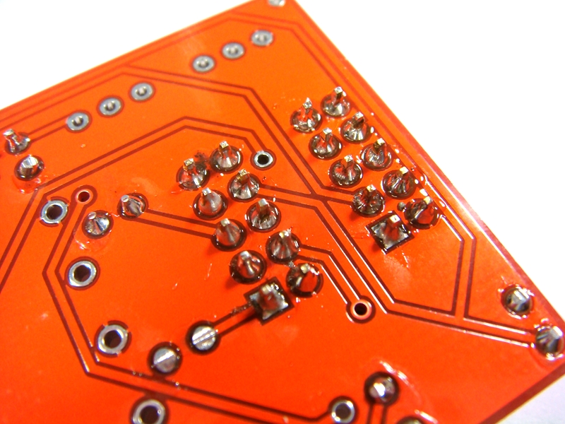
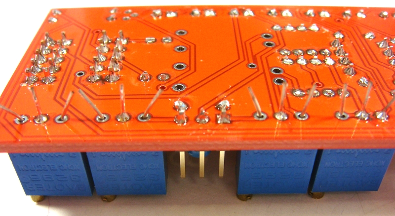
Solder all BAT85 diodes while holding PCB firmly upside down on flat surface. Make sure none of the center close pads are NOT shorted together.

Cut all diodes legs off at top of the solder joint and double check no solder joints missed soldering or are shorted together.
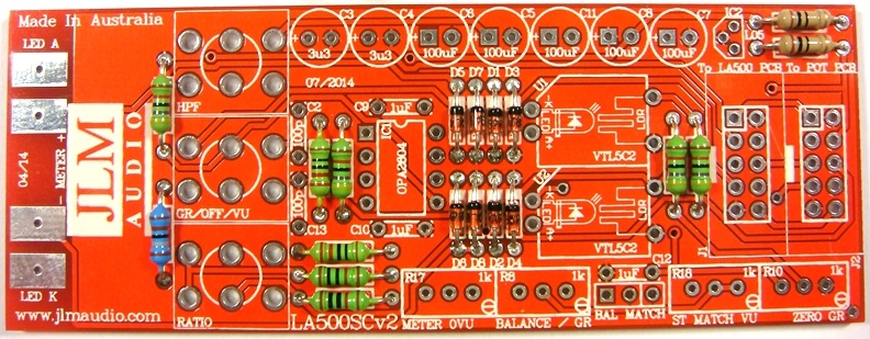
If you are not 100% with resistor colour codes use a multimeter to check values as you place the resistors
Fit all resistors at once bending the legs sightly outwards to hold them in place.
This helps to make sure no resistors are put in the wrong position.
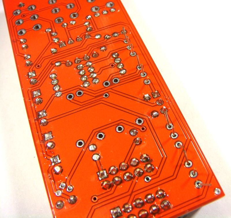
Solder all resistors while holding PCB firmly upside down on flat surface.
Cut all resistor legs off at top of the solder joint and double check no solder joints missed soldering.
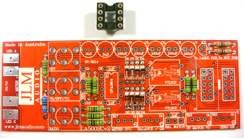
Fit and solder DIP8 socket in other opamp position. Make sure the POLARIZED socket matches the PCB overlay.
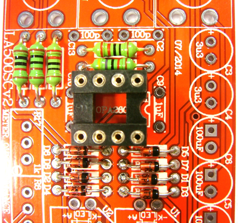
Fit and solder 3 x 1uF MONO caps in place.
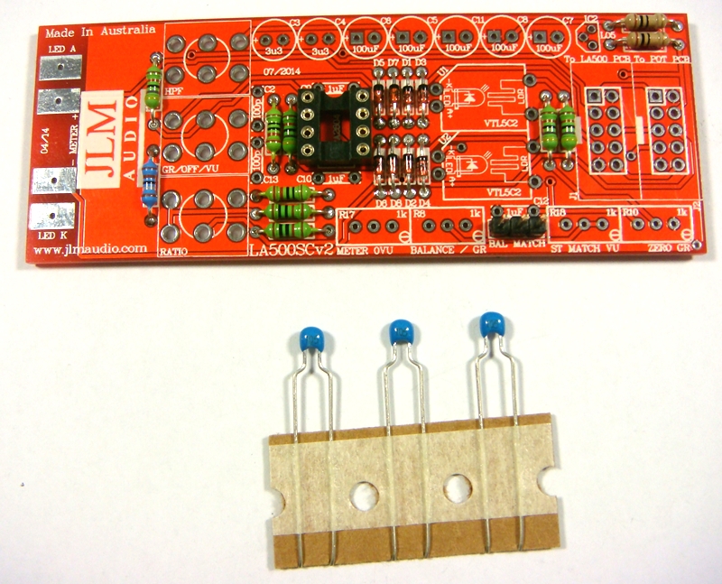
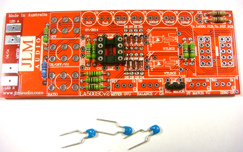
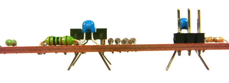
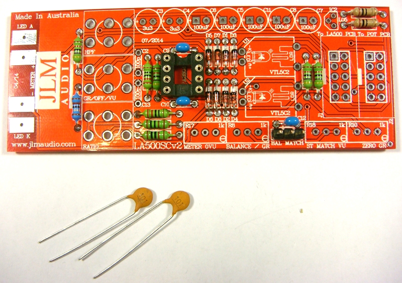
Fit 2 x 100pF ceramic caps in place.
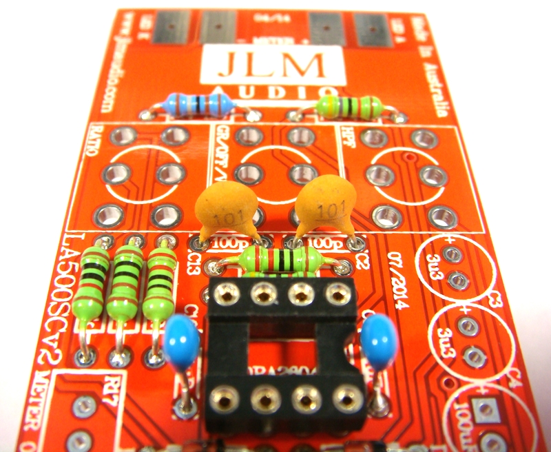
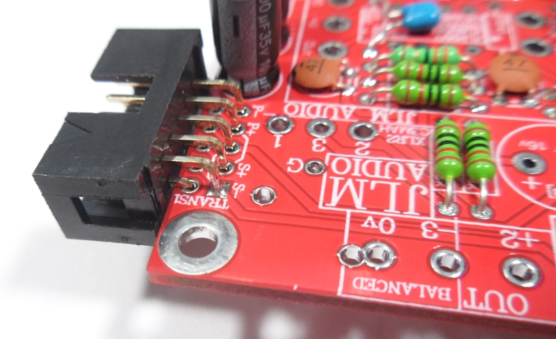
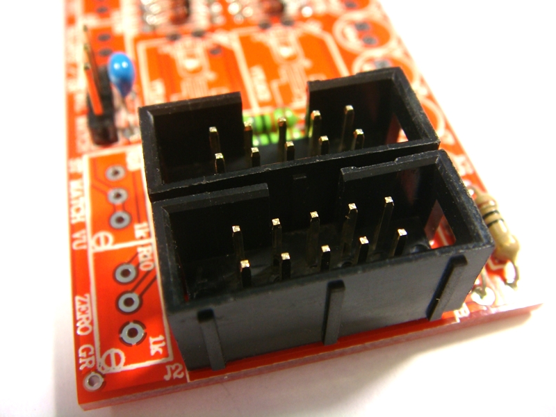
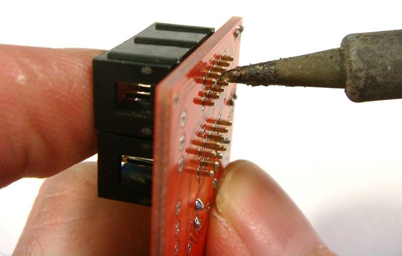
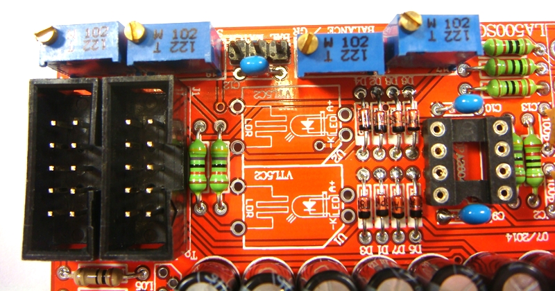
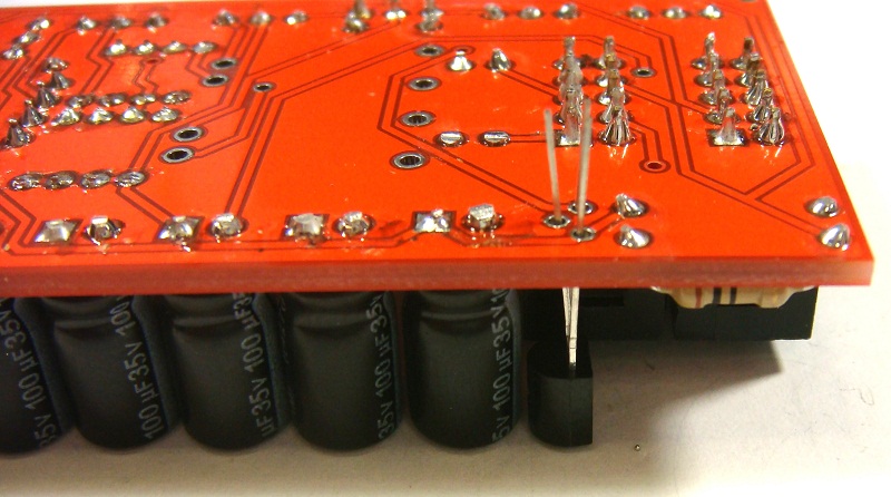
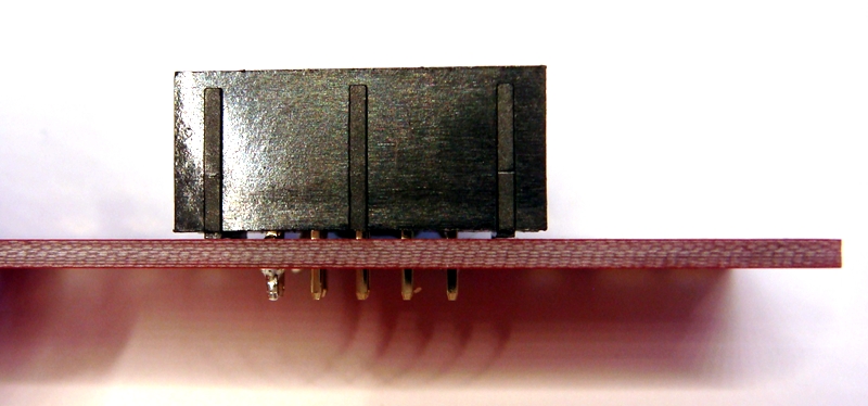
Fit and solder IDC headers in the POLARITY shown. Do not reverse. Triangle on header indicates pin 1 which is the square pad on the PCB.
The front opening in the IDC headers should both now be facing as shown below.
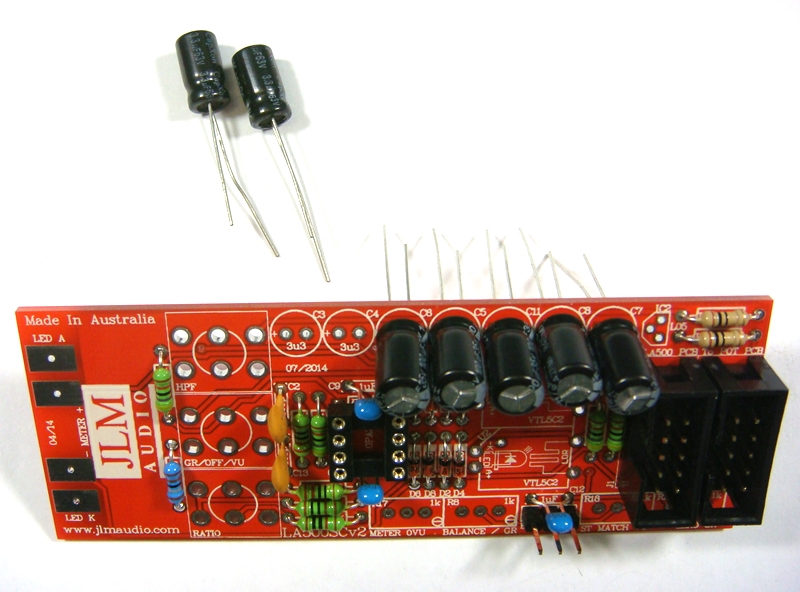
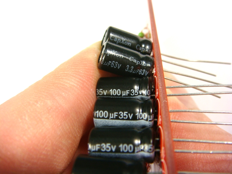
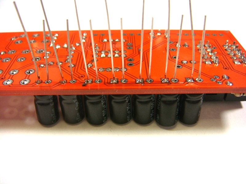
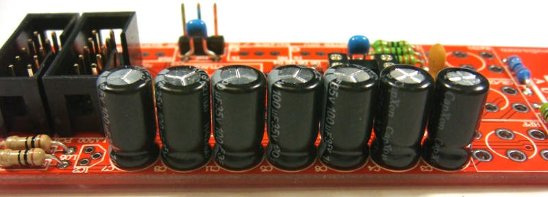
Fit and solder Electro caps to PCB. The 5 x 100uF caps are POLARIZED so must have there long positive leg fitted to + marked on PCB overlay.
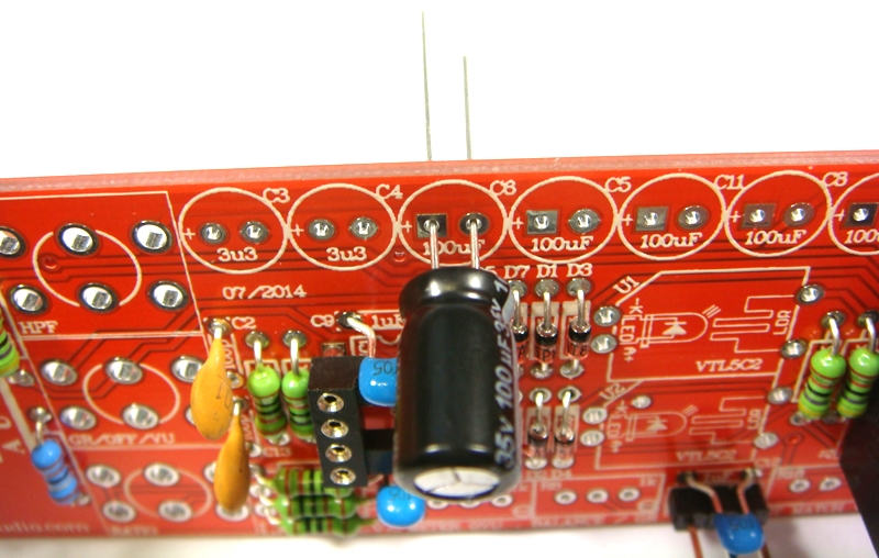
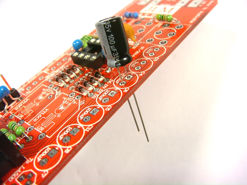
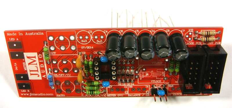
2 x 3.3uF acaps are NON polar types so can go in either way around on the PCB.
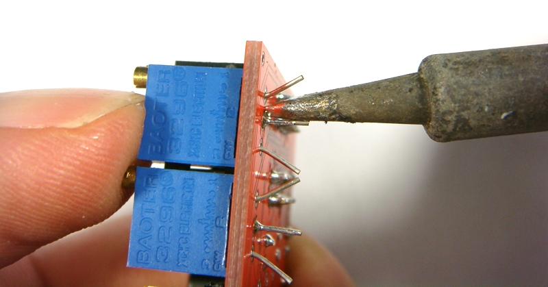
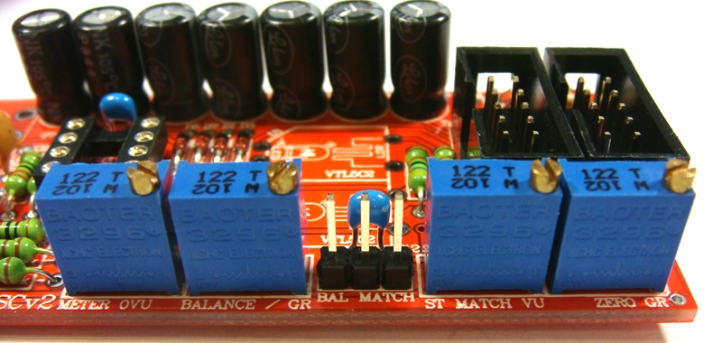
Fit and solder 4 trim pots as shown 1k = 102 code. Place pot so trim screw is in corner shown below
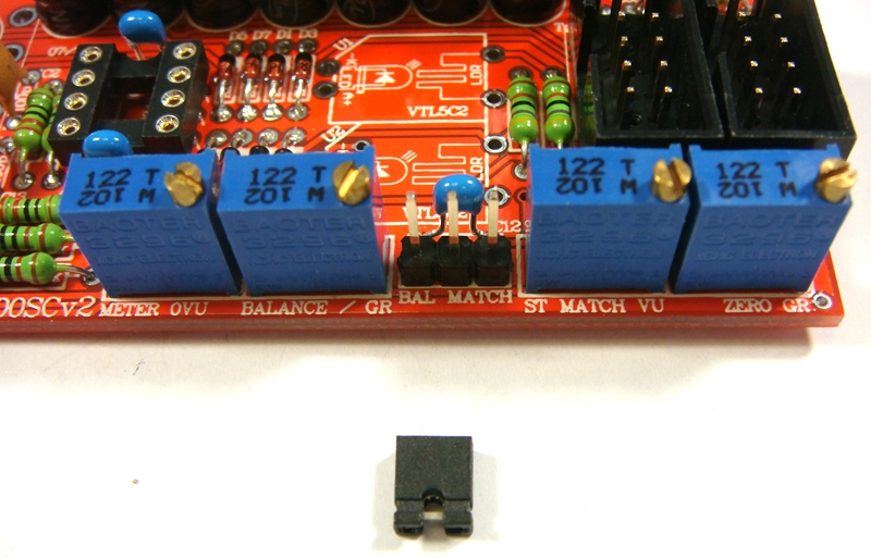
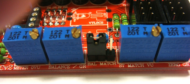
Fit and solder 3 pin header as shown below
Fit shunt to the 2 pins to the left
Fit and solder 78L05 5v regulator as shown below
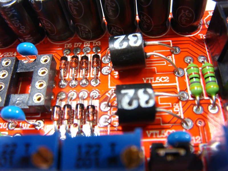
Fit and solder NSL32 optos as shown below. Short legs are LED & Long legs are LDR on NSL-32.
The NSL32 Cathode has a dot marked on the case which goes to -K. Be gentle with the wire legs on the opto when shaping them for the PCB.
Note: If you are building a stereo matched pair. Fit the 2 optos in the plastic bag marked U1 into the U1 position on each separate PCB and same for the bag with the U2 pair.
If building just one comp use the 2 optos in the bag and either opto can go into U1 or U2.
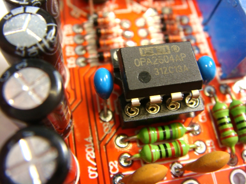
Plug in OPA2604AP opamp the correct way around as shown below and put the built LA500SCv2 and the 3 switches left over back in the plastic bag and move on to the LA500POTv2 kit.
Note LA500POT PCB has been replaced with dedicated MACPOTv2 (needs 2 jumper wires added) & now MACPOTv3
Just build the MACPOT pcbs as their overlay shows as no mods or changes are needed.
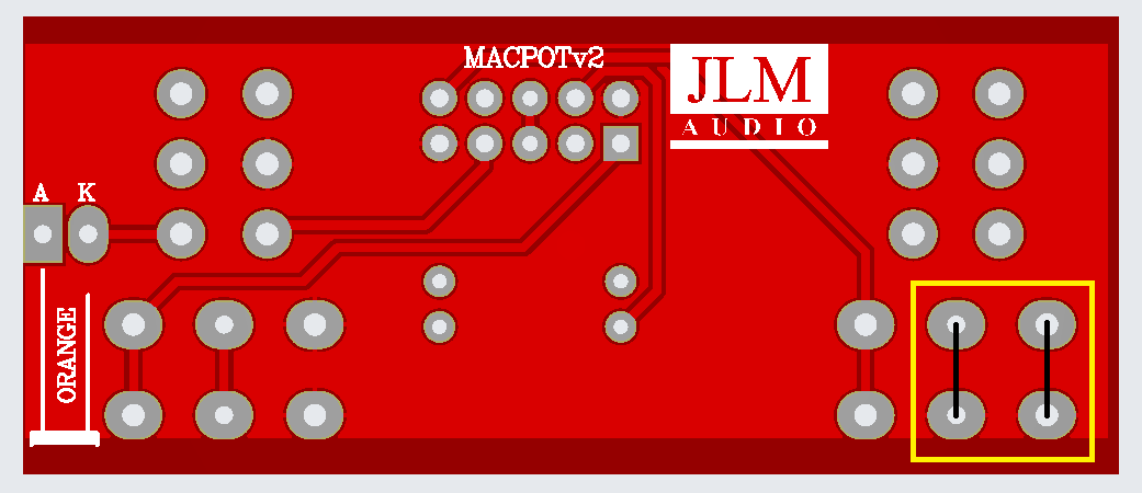
MACPOTv3 has the 2 missing 0v ground on the makeup pot pins fixed so the 2 jumpers are not needed.
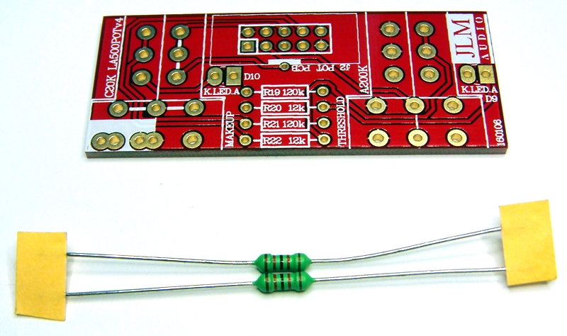
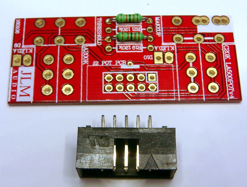
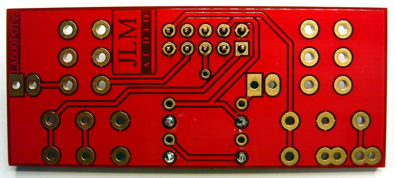
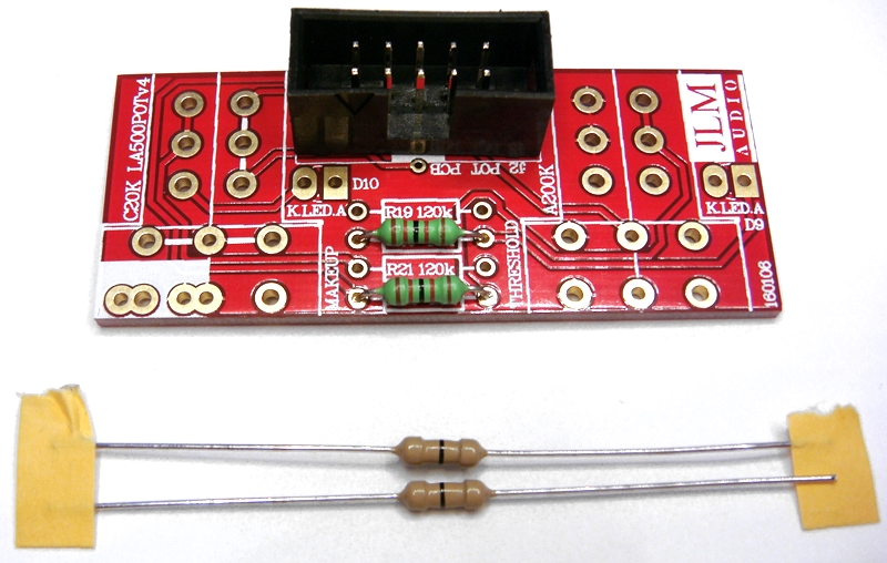
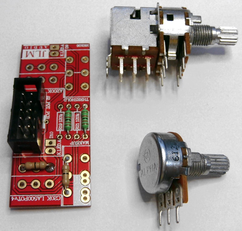
LA500POTv4 kit Custom build photos for MAC RACK kit
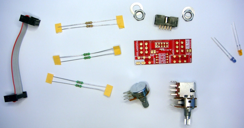
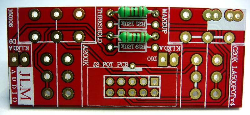
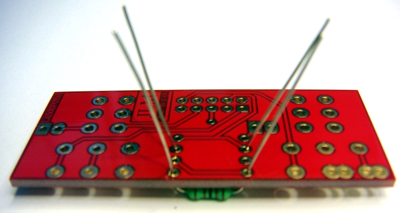
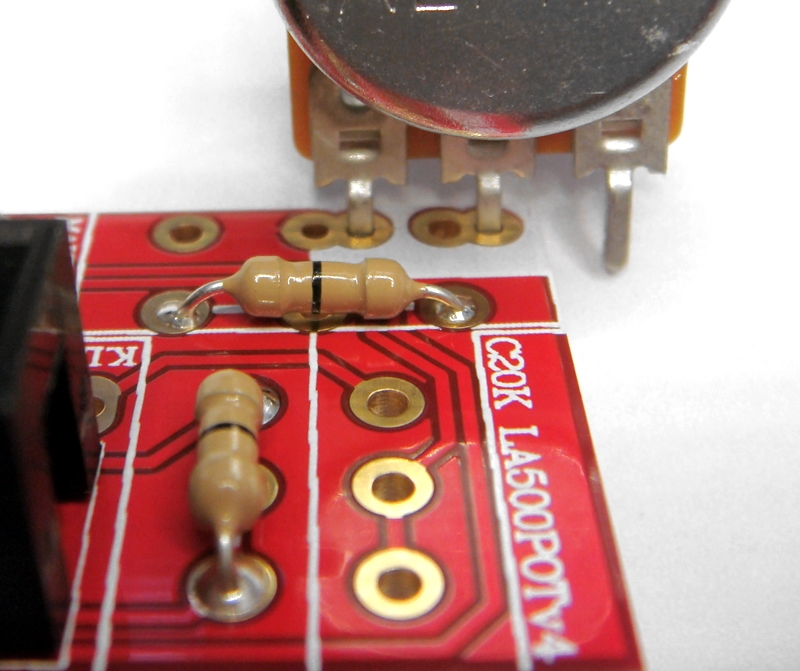
Start with fitting of the two 12k resistors into the PCB and bend the legs slightly outwards so they do not fall out when PCB is turned over.
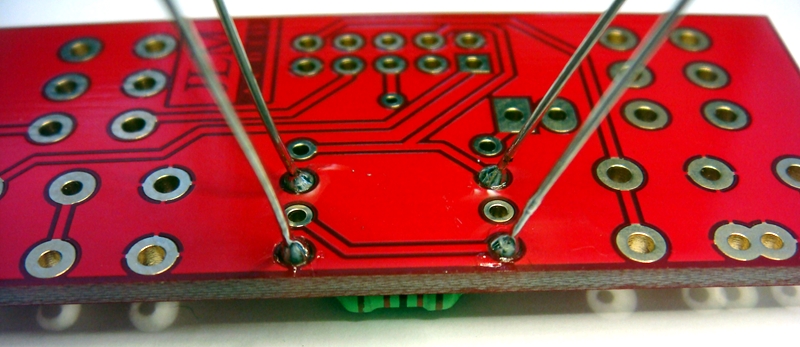
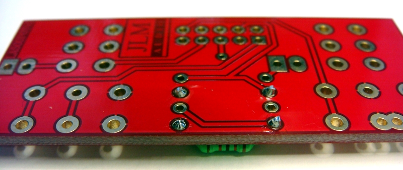
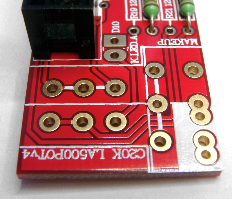
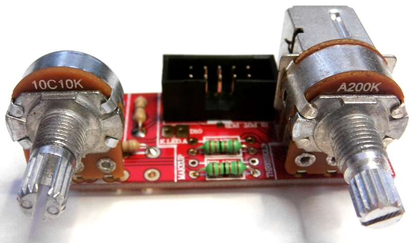
Fit 10 pin IDC header as shown below

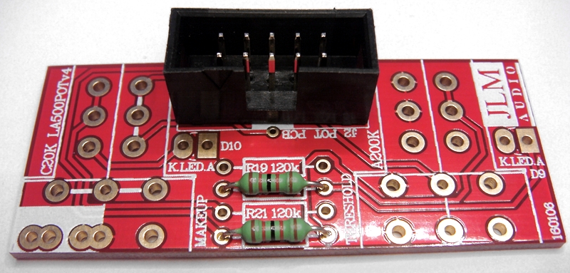
Fit 2 x 0ohm link resistors as shown below
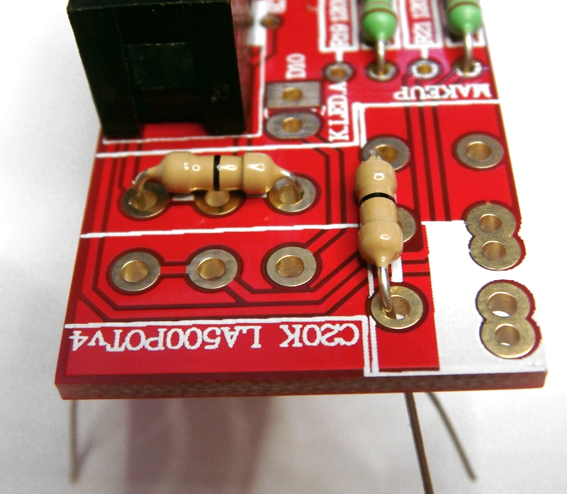
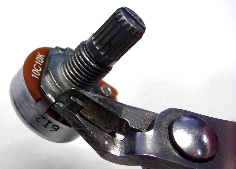
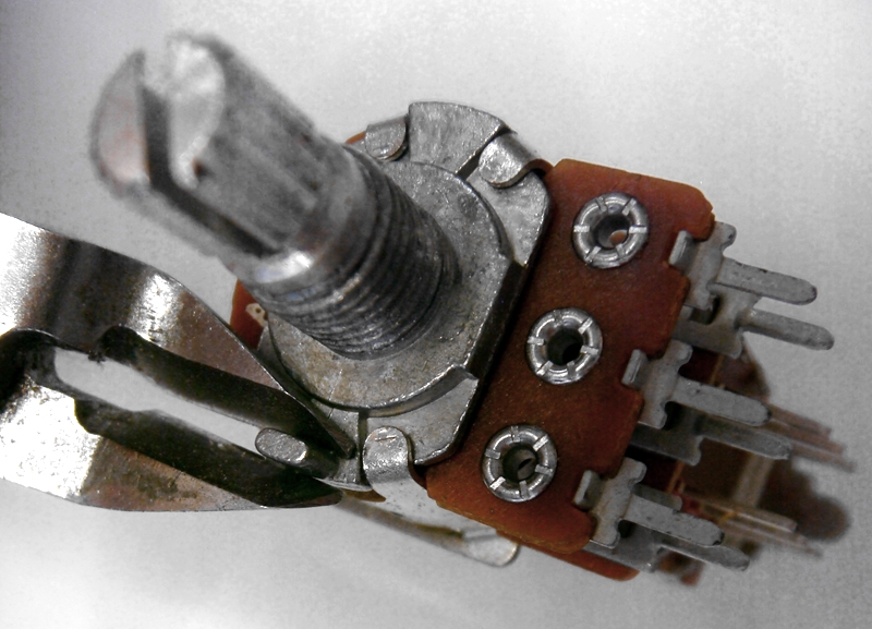
Cut off locate tabs on pots and fit as shown below
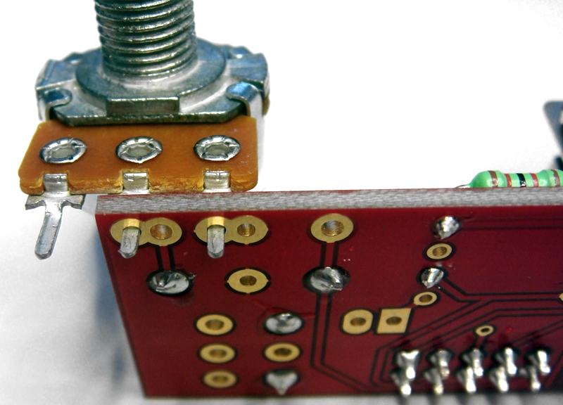
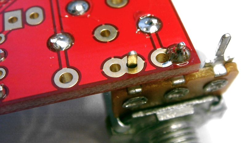
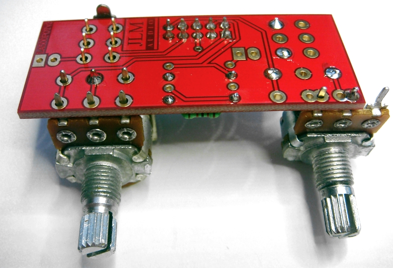

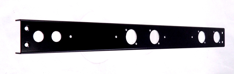
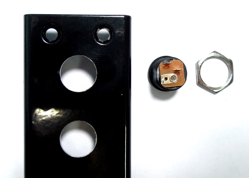
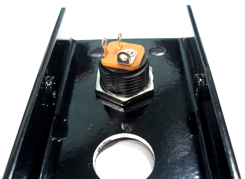
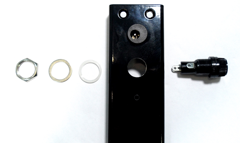
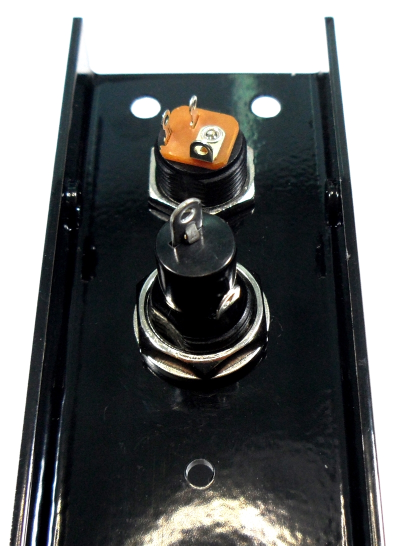
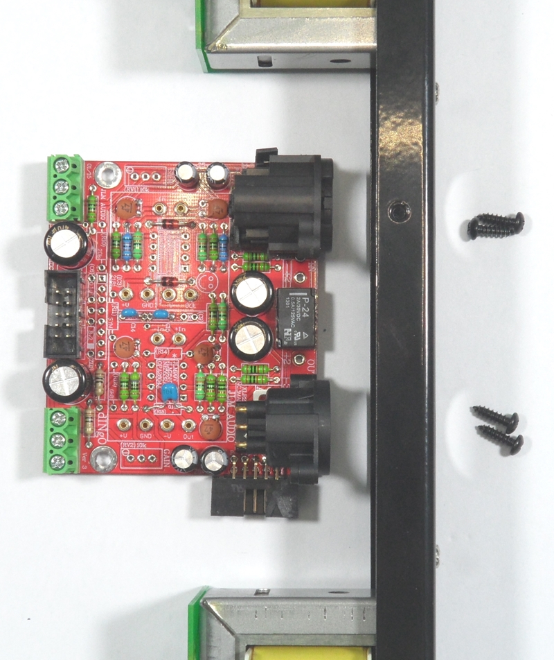
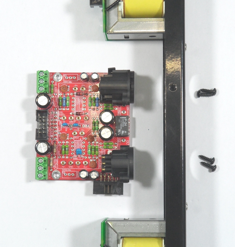
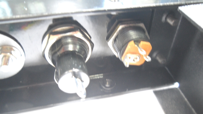
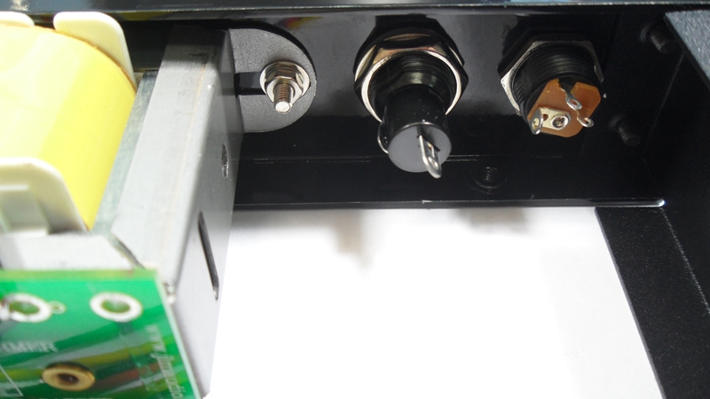
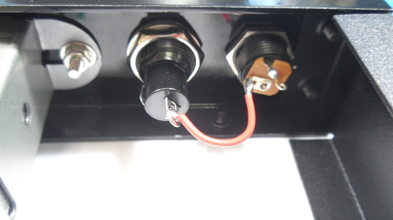
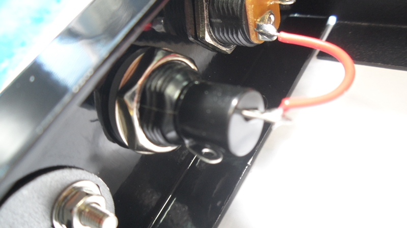
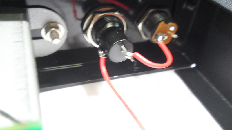
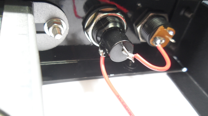
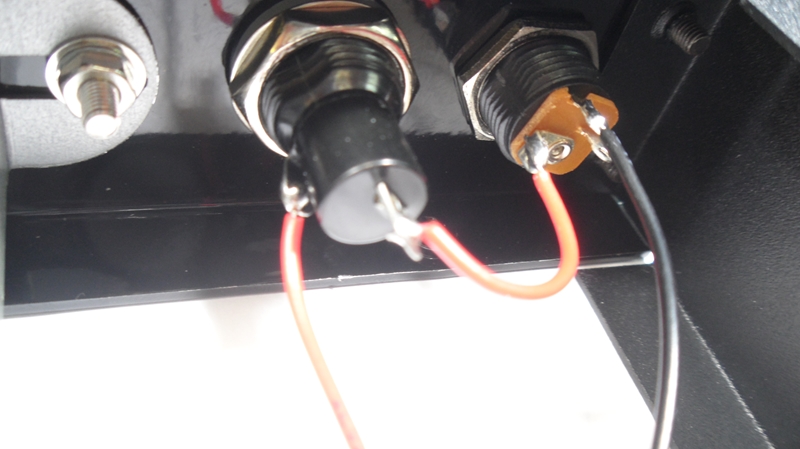
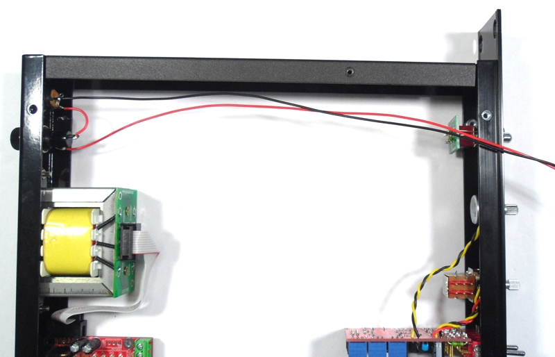
Bolt all pots and switches in place on the front panel. Pots must have there locate tags cut off as shown earlier on this page.
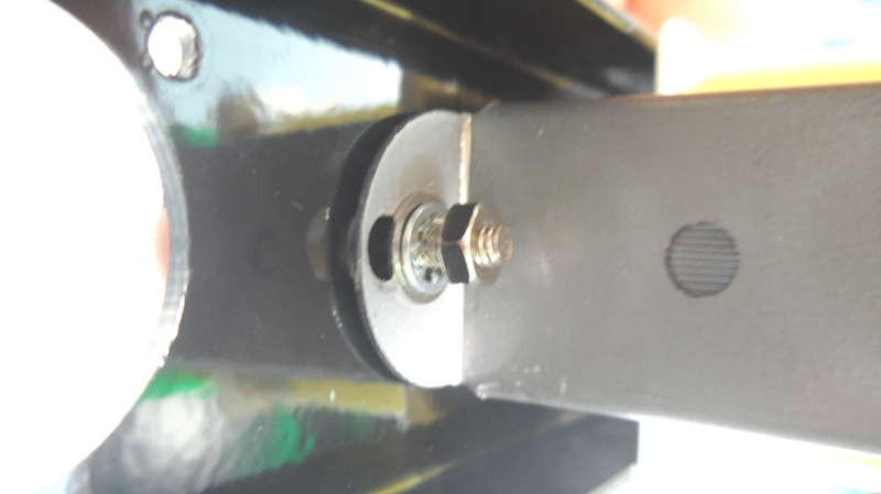
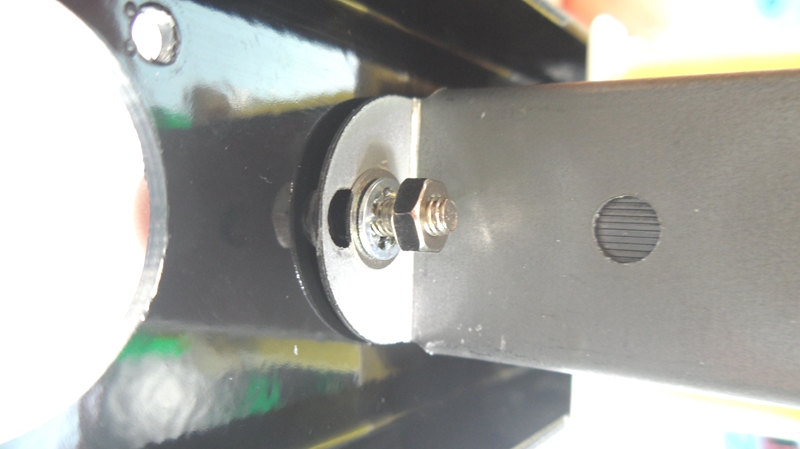
Switches should have the rear nut wound about 2mm up the thread and washer and lock washer go on the behind the front panel so when fitted to front panel only just enough thread for the front nut is left. This makes the fornt panel look correct and gives the length needed for mounting the MAC pcb on the end of the long switch legs.
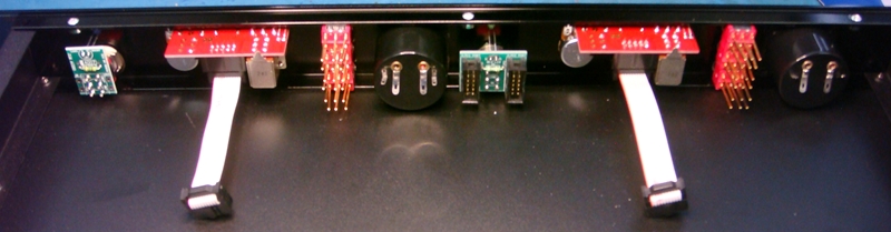
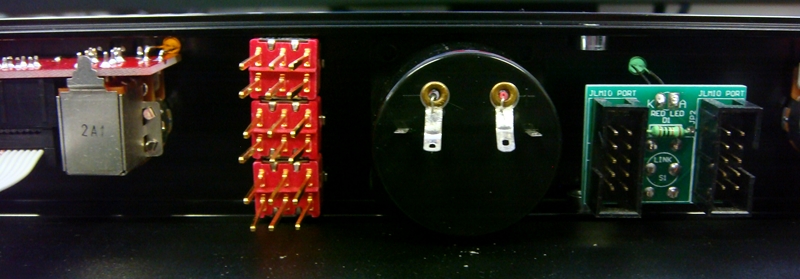
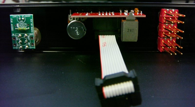
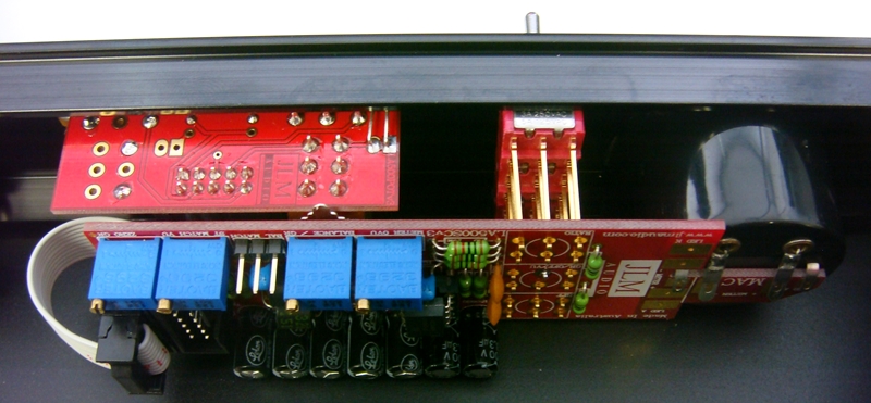


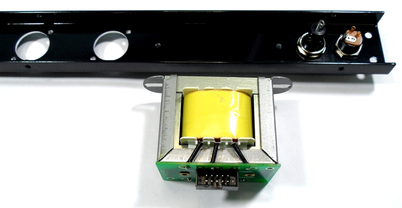

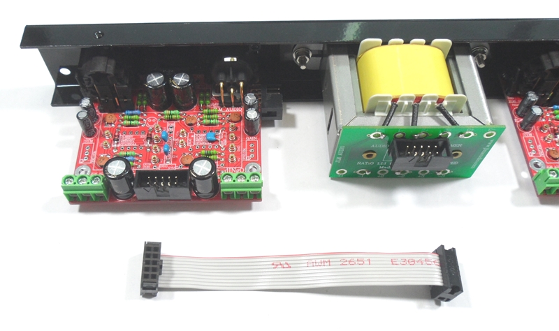
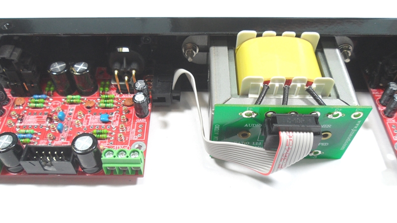
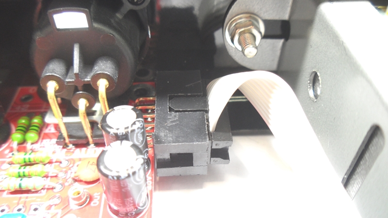
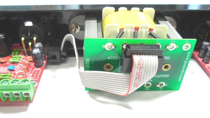
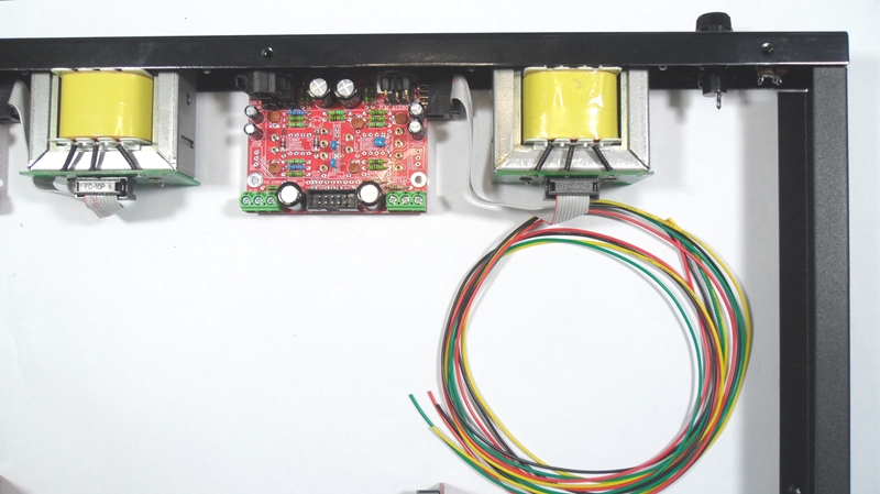


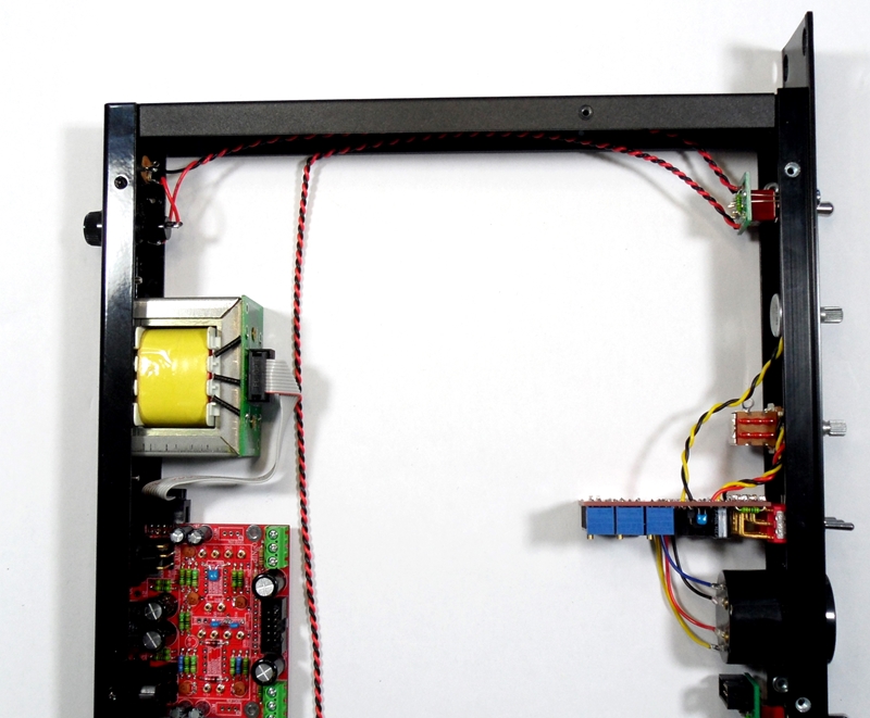
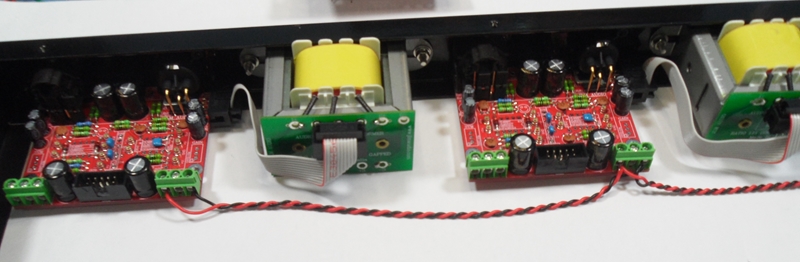
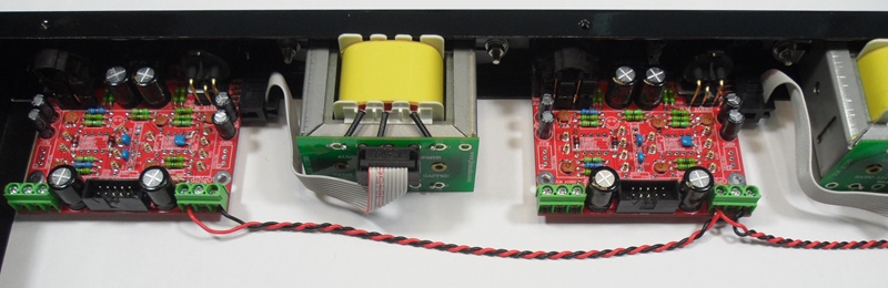
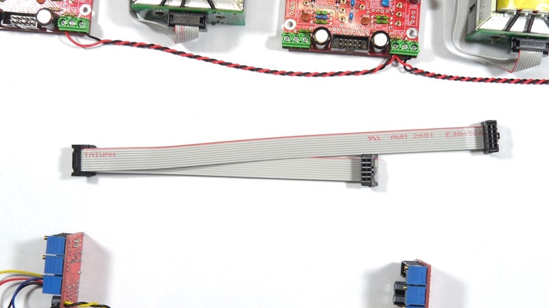
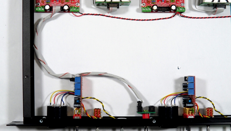
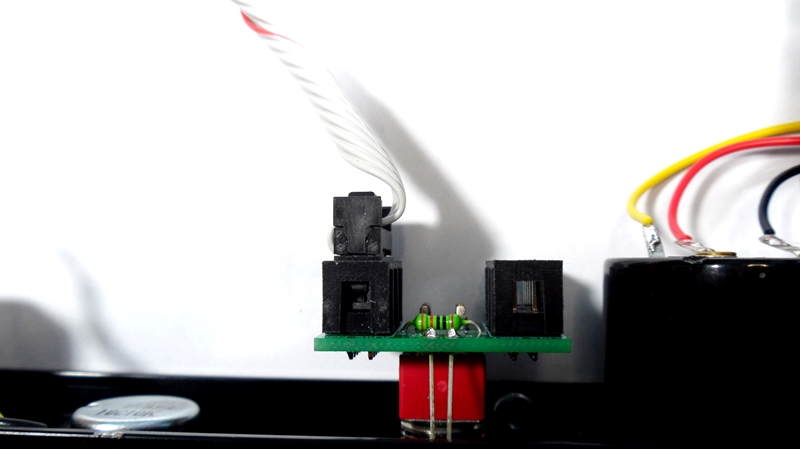
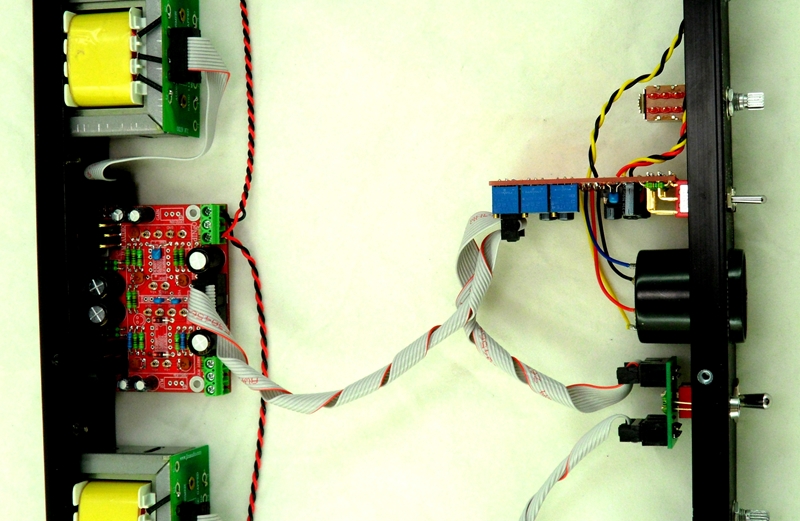
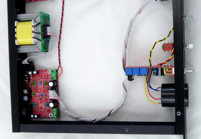
The photos below show the old mac pcbs in the original mac build thread but the ribbon cable works the same.
Plugs ribbon into the centre IDC10 on the dingo pcb to the IDC10 connector not on the edge of LA500SC pcb and then to the MAC link pcb.
(LA500SC pcb edge IDC10 is used by LA500POT pcb ribbon cable)

Compressor setup procedure
1. Set MAC to Threshold pot fully CCW, Makeup pot to CCW. Ratio switch to 3:1, Meter switch to VU, HPF switch to FLAT.
2. Apply 1kHz tone to MAC input so you have the reference level of +4dBu (1.23vac) on the MAC output between pin 2 & 3 of the XLR.
3. Or plug MAC output into VU or PPM meter that is calibrated to 0VU = +4dBu. If voltage not correct level adjust 1kHz generator level until correct.
4. Adjust meter 0VU trim pot for the desired level of 0VU on the meter.
5. Switch Meter switch to GR and adjust Zero GR trim pot for 0VU on the meter.
6. Switch back to VU and meter should be reading 0VU and turn up Threshold pot until you have -5dB on the meter.
7. Switch Meter switch between GR and VU and adjust the Balance trim pot until the same reading is seen in both GR and VU.
8. Check that with both channels set the same and link switch on meters both still read -5dB. If not realign both comps again.