Page 1 of 10
VU BUFFER & PEAK LED KIT BUILD THREAD
Posted: Tue Oct 15, 2013 2:08 pm
by Joe Malone
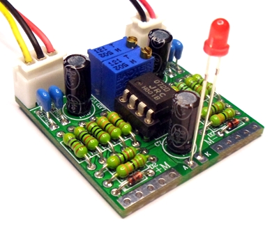
VU Buffer and peak led schematic
here
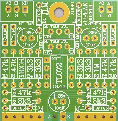
Assembly is the same as the original VU Buffer kit
here
Disabling the rectifier for meter with internal rectifiers is also the same.
VU Buffer & Peak led kit parts list
1 x VU PEAK PCB
1 x 3way connector
1 x 3way plug and cable
1 x 2way connector
1 x 2way plug and cable
1 x DIP8 IC SOCKET
1 x TL072 IC OPAMP
4 x BAT85 DIODE
1 x 3mm RED LED HIGH BRIGHT TYPE
1 x 3mm black bezel
2 x 5k 25turn trim pot
1 x 100R
6 x 3k3
6 x 47k
1 x 1MEG
4 x 1uF MONO CAP
3 x 10uF 63v electro CAP
To Setup VU Buffer and Peak LED pcb.
1. Connect dc power you are using. VU buffer and peak led can run on +12 to +36vdc @ 30mA so main current draw will usually be the VU meter light.
2. Send 1kHz tone in at the reference level you want for the VU meter like +4dBM for example.
3. Adjust Trimpot marked VU for correct 0VU level for your system.
4. Send 1kHz tone in at the reference level you want for the Peak LED meter like +18dBM for example.
5. Then adjust trimpot marked LED until the LED just lights.
Note to set high peak levels than +18dBM or +18dBu a power rail of more than +12vdc will be needed.
Re: VU BUFFER & PEAK LED KIT BUILD THREAD
Posted: Wed Dec 25, 2013 10:00 am
by permeke
just wondering if there is a mod on this pcb to alter the limit behaviour of the meter used.
let me explain, I have some vintage meters that I want to use , but somehow when they are at full scale , they got stuck at the very end. think it's a mechanical thing.
If I could adjust the response so that they just don't reach the very end, I would be a happy man.
Re: VU BUFFER & PEAK LED KIT BUILD THREAD
Posted: Thu Dec 26, 2013 8:08 am
by Joe Malone
permeke wrote:just wondering if there is a mod on this pcb to alter the limit behaviour of the meter used.
let me explain, I have some vintage meters that I want to use , but somehow when they are at full scale , they got stuck at the very end. think it's a mechanical thing.
If I could adjust the response so that they just don't reach the very end, I would be a happy man.
Analog meters overshoot so there is no way to limit them at 100% full scale.
You just need to fix the end stop so the needle doesn't stick to it. Or bend the needle so it doesn't touch the scale or front glass.
You can usually add a small bit of plastic tube to the metal end stop so it doesn't stick to the needle.
Re: VU BUFFER & PEAK LED KIT BUILD THREAD
Posted: Thu Apr 17, 2014 10:47 am
by jpertusi
Howdy,
I just got my pair of JLM Large Meters and 2 of the buffer kits with peak LEDs.
I've got a few questions:
Do the lamps need their own power or can they be run from the voltage coming in to the pcb?
I assume the PCB is not meant to be directly mounted to the meter housing?
Is the red led meant to be inside the meter housing so the entire meter face lights red when it peaks?
Any help is appreciated,
Thanks,
-JP
Re: VU BUFFER & PEAK LED KIT BUILD THREAD
Posted: Thu Apr 17, 2014 11:46 am
by Joe Malone
jpertusi wrote:Howdy,
I just got my pair of JLM Large Meters and 2 of the buffer kits with peak LEDs.
I've got a few questions:
Do the lamps need their own power or can they be run from the voltage coming in to the pcb?
Yes using the 12vdc to 24vdc can be used to run the buffer and lamps. Most meter have 12v or 6v lamps so running them in series or parellel will usually get them to match the voltage the buffer is running on.
I assume the PCB is not meant to be directly mounted to the meter housing?
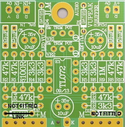
Often the PCB is mounted directly to the meter terminals as you will see in the original VU buffer build thread with the photos. But new VU buffer peak led kit also has one mounting hole so PCB can be mounted to case etc.
Is the red led meant to be inside the meter housing so the entire meter face lights red when it peaks?
Usually it is just mounted on the front panel outside the meter
or
Some guys drill a small 3mm hole in the top right corner of the meter itself but you have to be very careful and know what you are doing. So not a good idea for a beginner
Any help is appreciated,
Thanks,
-JP[/quote]
Re: VU BUFFER & PEAK LED KIT BUILD THREAD
Posted: Fri Jul 04, 2014 11:24 am
by stitchy
Hello!
I have a Buffer Peak kit I built and Im not sure were my issue is.
Attached are pics of the VU and circuit.
It is vintage and I believe a real VU. It is attached from output of your buffer amp.
I measured audio AC at your buffer input.
DC power rail is measured at 10.76VDC at Buffer amps DC input.
No VU movement tho.
My question to make it easy to see if I put the PCB together incorrectly or I have a bum VU: Would the over/clip LED still light if I sent an excessive input signal?
Is there an easy way to test if the VU is not working?
photo3.JPG
photo1.JPG
photo2.JPG
Re: VU BUFFER & PEAK LED KIT BUILD THREAD
Posted: Sun Jul 06, 2014 9:07 am
by Joe Malone
stitchy wrote:Hello!
I have a Buffer Peak kit I built and Im not sure were my issue is.
Attached are pics of the VU and circuit.
It is vintage and I believe a real VU. It is attached from output of your buffer amp.
I measured audio AC at your buffer input.
DC power rail is measured at 10.76VDC at Buffer amps DC input.
No VU movement tho.
My question to make it easy to see if I put the PCB together incorrectly or I have a bum VU: Would the over/clip LED still light if I sent an excessive input signal?
Is there an easy way to test if the VU is not working?
(From the email I sent you.)If it is a real VU meter does it run directly wired across a audio signal with no buffer?
This will prove if the meter is working and/or has a internal rectifier. If it has no rectifier the needle will wiggle around the minimum settings of the meter.
The peak working depends on its trim pot setting and the power rail you are running the VU buffer on ? So if you have haven't touch the trim pot from when the kit was built the LED will light with high levels once you have set the VU trim to show +4dBM = 0VU.
What are the 3 input wires to the buffer wired too? Yellow? Red? Black?
Re: VU BUFFER & PEAK LED KIT BUILD THREAD
Posted: Mon Jul 07, 2014 4:18 am
by stitchy
Joe Malone wrote:stitchy wrote:Hello!
I have a Buffer Peak kit I built and Im not sure were my issue is.
Attached are pics of the VU and circuit.
It is vintage and I believe a real VU. It is attached from output of your buffer amp.
I measured audio AC at your buffer input.
DC power rail is measured at 10.76VDC at Buffer amps DC input.
No VU movement tho.
My question to make it easy to see if I put the PCB together incorrectly or I have a bum VU: Would the over/clip LED still light if I sent an excessive input signal?
Is there an easy way to test if the VU is not working?
(From the email I sent you.)If it is a real VU meter does it run directly wired across a audio signal with no buffer?
This will prove if the meter is working and/or has a internal rectifier. If it has no rectifier the needle will wiggle around the minimum settings of the meter.
The peak working depends on its trim pot setting and the power rail you are running the VU buffer on ? So if you have haven't touch the trim pot from when the kit was built the LED will light with high levels once you have set the VU trim to show +4dBM = 0VU.
What are the 3 input wires to the buffer wired too? Yellow? Red? Black?
Hi Joe!
Thanks for the replies.
The VU, with direct input from audio, works and does much more than minimal, so I think it both works and
has a rectifier.
The 3 input wires are yellow- shield, Black - low audio, red - hi audio....
EDIT I think I got it! bad solder point, VU now fed by buffer amp.
THANKS Joe!!
-s
Re: VU BUFFER & PEAK LED KIT BUILD THREAD
Posted: Mon Jul 07, 2014 7:36 am
by Joe Malone
Cool good to hear you got it going

Re: VU BUFFER & PEAK LED KIT BUILD THREAD
Posted: Thu Feb 12, 2015 9:29 pm
by costes
Hi,
Could anyone confirm the peak led voltage coming from the pcb is 1,3v?
Thank you very much
Re: VU BUFFER & PEAK LED KIT BUILD THREAD
Posted: Sat Feb 14, 2015 1:17 pm
by Joe Malone
costes wrote:Hi,
Could anyone confirm the peak led voltage coming from the pcb is 1,3v?
Thank you very much
Peak led on voltage coming from the PCB with no led attached is the voltage you are running the VU buffer / Peak LED kit on but with a series 47k resistor to limit current to the 2v red high brightness led supplied. So with LED attached and permanently on you will get a reading of 1.6 to 2.2v across the LED.
Re: VU BUFFER & PEAK LED KIT BUILD THREAD
Posted: Thu Jul 02, 2015 9:14 pm
by JeremyStarseed
Hi, I'm wondering if a 500 µA DC = FS (DB meter) constitutes a "real VU meter" and if it can be used with the buffer kit? Would it need any additional resistors or modification?
Bought a few kits...and so I'm wondering if another pair of 1 mA DC meters would suit the buffer to display standard VU action? If so, this circuit is a winner. If not...many gain reduction gauges use 1 mA DC...so, no problem. If yes...would swapping polarity allow me to rotate one of the meters? They're square and would look really funky with symmetric movement.
Thanks!
Re: VU BUFFER & PEAK LED KIT BUILD THREAD
Posted: Mon Jul 06, 2015 10:12 am
by Joe Malone
JeremyStarseed wrote:Hi, I'm wondering if a 500 µA DC = FS (DB meter) constitutes a "real VU meter" and if it can be used with the buffer kit? Would it need any additional resistors or modification?
Bought a few kits...and so I'm wondering if another pair of 1 mA DC meters would suit the buffer to display standard VU action? If so, this circuit is a winner. If not...many gain reduction gauges use 1 mA DC...so, no problem. If yes...would swapping polarity allow me to rotate one of the meters? They're square and would look really funky with symmetric movement.
Thanks!
HI Jeremy Both 500uA and 1mA DC meters will work with the VU buffer kits perfectly without any series resistor or changes needed.
You usually cannot rotate a meter but if the needle position screw allows you to set the meter to sit fully at the other end of the scale then yes swapping polarity will make the needle move backwards.
Re: VU BUFFER & PEAK LED KIT BUILD THREAD
Posted: Mon Apr 11, 2016 3:42 am
by jensenmann
Hi Joe
I need to make my VU buffers switchable between 0VU=+4dBu and 0VU=+14dBu, while the peak LED is supposed to always monitor the same level (+18dBu). Do you see an easier solution than lifting one leg of VR1 and VR2 and switching resistors in line/out of line with these?
thanks
Jens
Re: VU BUFFER & PEAK LED KIT BUILD THREAD
Posted: Mon Apr 11, 2016 7:51 am
by Joe Malone
jensenmann wrote:Hi Joe
I need to make my VU buffers switchable between 0VU=+4dBu and 0VU=+14dBu, while the peak LED is supposed to always monitor the same level (+18dBu). Do you see an easier solution than lifting one leg of VR1 and VR2 and switching resistors in line/out of line with these?
thanks
Jens
HI Jens Cal the VU for 0VU = +4dBu and set peak led and switch a resistor in series with the meter for the 0VU = +14dBu. This resistor value varies between between meter types of course.
If the range is to wide then your solution is the only way. But 10dB should work fine with the series resistor.