VU2 stereo VU buffer kit Build thread
Posted: Fri Sep 28, 2012 8:59 am
PLEASE READ ALL NOTES & ERRATA BEFORE STARTING ASSEMBLY
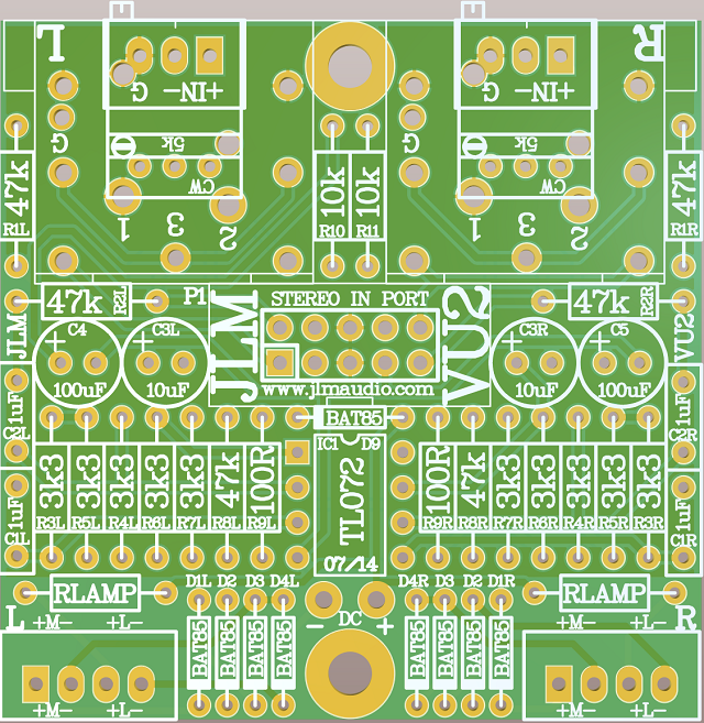
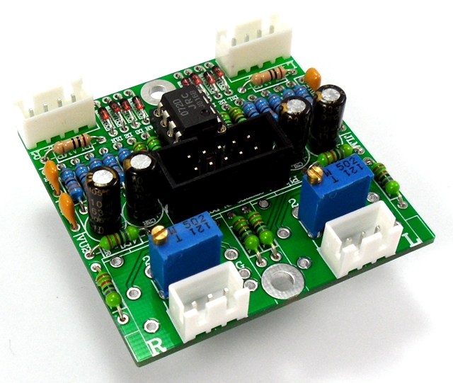
VU2 stereo VU buffer PCB
PCB can be power using the +/-DC solder pads or the IDC10 header as used on our AMP HEAD kit.
If using single rail +DC can be +12v to +36v and -DC wired to 0v.
If using dual +/-rail +DC can be +6 to +18v and -DC can be -6 to -18v. (NO 0v power rail is connected when dual rails are used)
47k = Yellow Violet Black red
3k3 = Orange Orange Black Brown
100R = Brown Black Black Black
VU2 Stereo buffer kit parts list here
INPUTS
3 OPTIONS (You can also have XLR and TRS at the same time by adding a Stereo in kit.)
XLR PCB Mount (one for left and one for right channel)
TRS PCB Mount (one for left and one for right channel)
3 pin connectors (one for left and one for right channel)
IN+ = + Balanced input signal (Unbalanced + input) (Red Wire)
IN- = - Balanced input signal (Unbalanced shield) (Black Wire)
G = 0v ground shield (Not used for unbalanced input) (Yellow Wire)
OUTPUTS
4 pin connectors (one for left and one for right channel)
M+ = Meter + terminal (Yellow wire)
M- = Meter - terminal (White wire)
L+ = Lamp + terminal (Red wire)
L- = Lamp - terminal (Black wire)
Notes & Errata
Some VU2 kits have shipped with (501) 500ohm trimpots instead of (502) 5k trimpot
501 500ohm trimpots will work for inputs of +4dBu balanced or lower but please contact us if you have the wrong trimpots
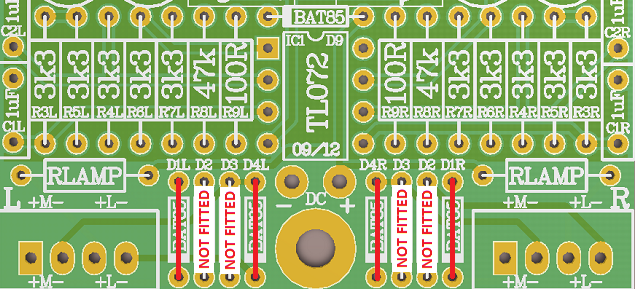
Note 1. When using a meter with internal rectifiers do the mod shown below to disable the VU buffer rectifier.
Note 2. If trimpot is fitted the opposite way to what the overlay shows buffer it will work fine but gain will increase counter clockwise.
Note 3. If you need more gain change R7L & R7R from 3k3 down to a minimum of 100R. It is also then worth putting a red LED or or 2 x 1N4007 in series across the meter +(Anode) /-(Cathode) terminals to limit & protect the meter in overload conditions. You can also get more gain by changing R9L & R9R from 100R down to minimum of 22R or 10R.
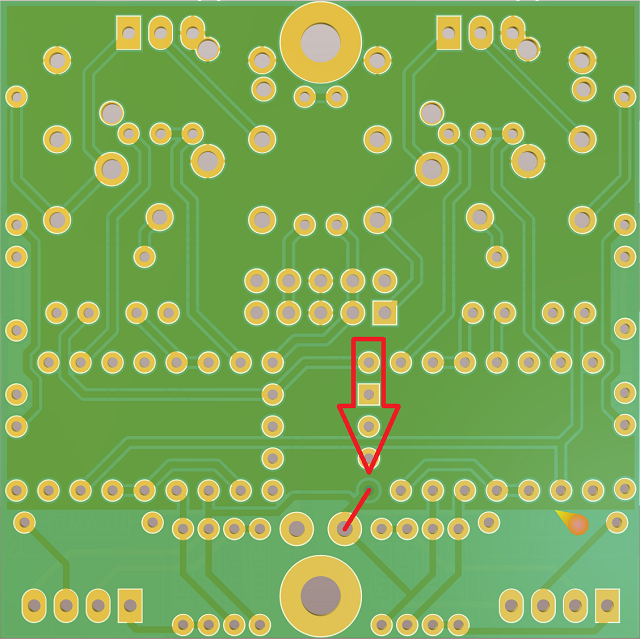
Note 4.Current VU2 pcb has pin 4 of the IC socket masked over so best to solder a cut off component leg form that pin to -DC as shown below.
RLamp values for LED or Bulb
If you want to run a LED fit RLamp of 3k3. or use this formula to work out the resistor value for the brightest LED R = (V - 2) / 0.02. Where V is the voltage running the VU buffer.
If you want to run a Bulb fit RLamp of 10R for soft start and run the VU buffer on the same voltage as the lamp needs. Like 12v or 24v etc.
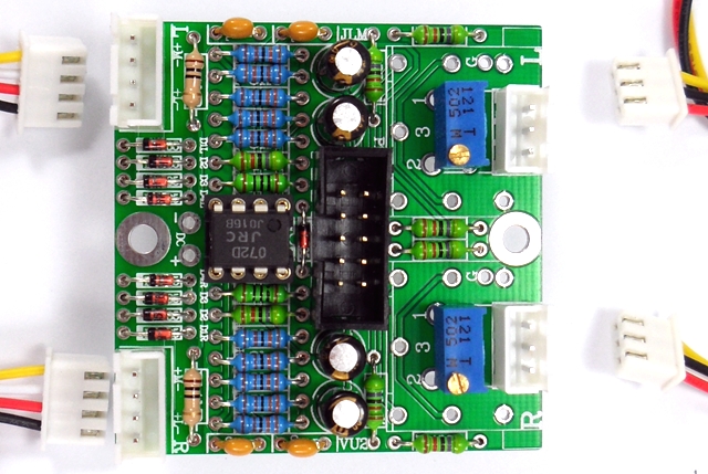
NOTE ALL PHOTOS BELOW SHOW THE TRIM POTS FITTED THE WRONG WAY AROUND.
BRASS SCREW SHOULD ON OPPOSITE SIDE

For step by step build info the rest of the VU2 is the same as the Mono VU buffer kit build thread here
VU2 stereo VU buffer PCB
PCB can be power using the +/-DC solder pads or the IDC10 header as used on our AMP HEAD kit.
If using single rail +DC can be +12v to +36v and -DC wired to 0v.
If using dual +/-rail +DC can be +6 to +18v and -DC can be -6 to -18v. (NO 0v power rail is connected when dual rails are used)
47k = Yellow Violet Black red
3k3 = Orange Orange Black Brown
100R = Brown Black Black Black
VU2 Stereo buffer kit parts list here
INPUTS
3 OPTIONS (You can also have XLR and TRS at the same time by adding a Stereo in kit.)
XLR PCB Mount (one for left and one for right channel)
TRS PCB Mount (one for left and one for right channel)
3 pin connectors (one for left and one for right channel)
IN+ = + Balanced input signal (Unbalanced + input) (Red Wire)
IN- = - Balanced input signal (Unbalanced shield) (Black Wire)
G = 0v ground shield (Not used for unbalanced input) (Yellow Wire)
OUTPUTS
4 pin connectors (one for left and one for right channel)
M+ = Meter + terminal (Yellow wire)
M- = Meter - terminal (White wire)
L+ = Lamp + terminal (Red wire)
L- = Lamp - terminal (Black wire)
Notes & Errata
Some VU2 kits have shipped with (501) 500ohm trimpots instead of (502) 5k trimpot
501 500ohm trimpots will work for inputs of +4dBu balanced or lower but please contact us if you have the wrong trimpots
Note 1. When using a meter with internal rectifiers do the mod shown below to disable the VU buffer rectifier.
Note 2. If trimpot is fitted the opposite way to what the overlay shows buffer it will work fine but gain will increase counter clockwise.
Note 3. If you need more gain change R7L & R7R from 3k3 down to a minimum of 100R. It is also then worth putting a red LED or or 2 x 1N4007 in series across the meter +(Anode) /-(Cathode) terminals to limit & protect the meter in overload conditions. You can also get more gain by changing R9L & R9R from 100R down to minimum of 22R or 10R.
Note 4.Current VU2 pcb has pin 4 of the IC socket masked over so best to solder a cut off component leg form that pin to -DC as shown below.
RLamp values for LED or Bulb
If you want to run a LED fit RLamp of 3k3. or use this formula to work out the resistor value for the brightest LED R = (V - 2) / 0.02. Where V is the voltage running the VU buffer.
If you want to run a Bulb fit RLamp of 10R for soft start and run the VU buffer on the same voltage as the lamp needs. Like 12v or 24v etc.
NOTE ALL PHOTOS BELOW SHOW THE TRIM POTS FITTED THE WRONG WAY AROUND.
BRASS SCREW SHOULD ON OPPOSITE SIDE
For step by step build info the rest of the VU2 is the same as the Mono VU buffer kit build thread here