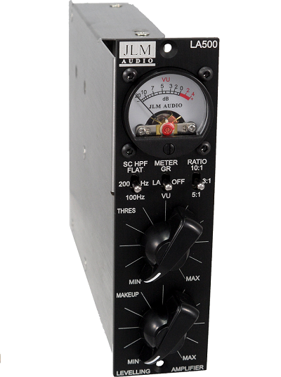
LA500 opto comp leveling amp BUILD THREAD 500/51X
Posted: Tue Oct 04, 2011 12:45 pm
The LA500 is a 500/51x version of our well know MAC opto comp rack version.
For an idea on what the LA500 / MAC comp can do read this AT mag review here
New LA500 slow release attack mod info is http://www.jlmaudio.com/forum/viewtopic.php?f=2&t=253
LA500 recall sheet here
PDF of this build thread here
(PDF made by Eric Sills http://www.stonesouprec.com
 )
)
LA500 Parts List
http://www.jlmaudio.com/LA500/LA500%20C ... 20list.txt
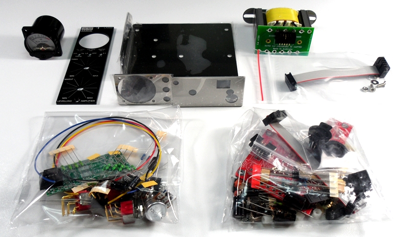
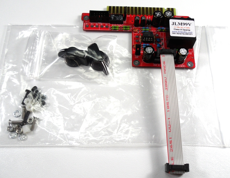
Complete LA500 kit with every part down to the last nut and bolt.
LA500 PCB schematic
http://www.jlmaudio.com/LA500/LA500%20S ... 120304.pdf
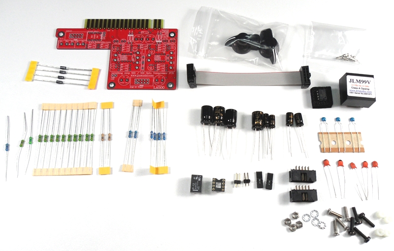
LA500 PCB kit
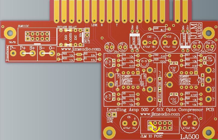
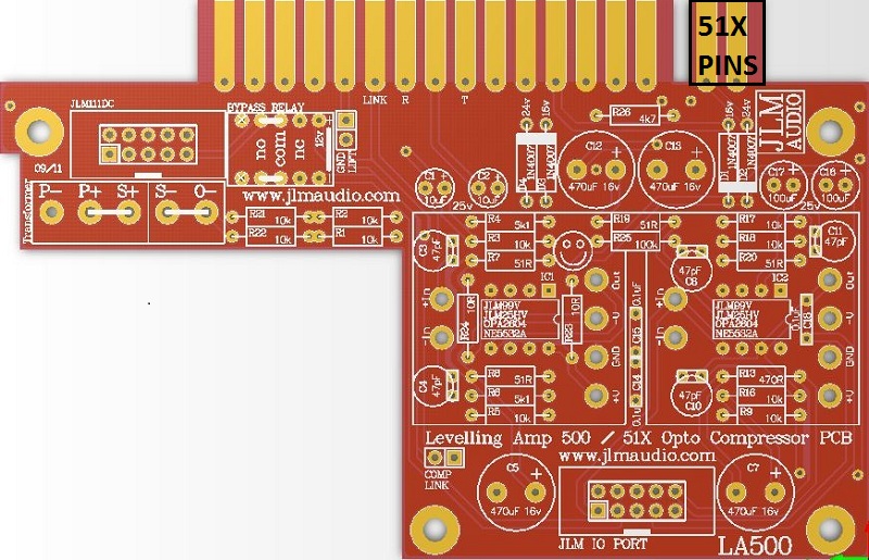
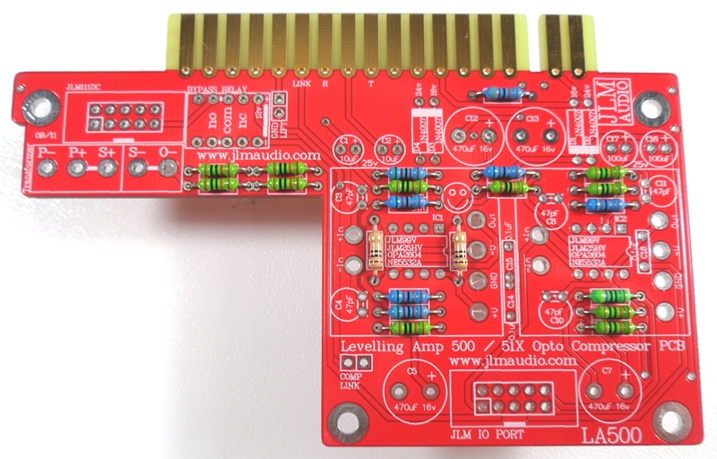
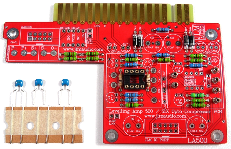
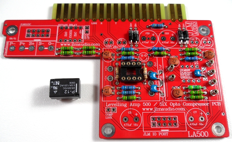
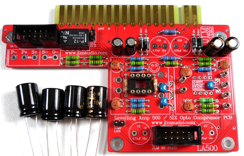
1. LA500 main pcb is a stripped down INX5 pcb so its overlay has the exact parts and values marked on it for the LA500 kit to make the build easy.
2. 51X and 500 compatible with 51X pins cut off. Kit fits all 500 and 51X racks and lunchboxes.
3. PCB automatically uses highest power available. +/-16v for 500 and +/-24v for 51X.
4. LA500 PCB also has mix buss out on pin 11 for Radial Workhorse racks.
LA500 PCB. For 500 series racks cut and file 51X pins off)
Notes and Errata
Note 1. Replacing R19 51R with new 33R give slightly better low frequencies response when using JLM111DC and JLM111DC compact output transformer.
In future kits we will be replacing all 51R with 33R. So R19 and R20 will both be changed to 33R on new PCBs.
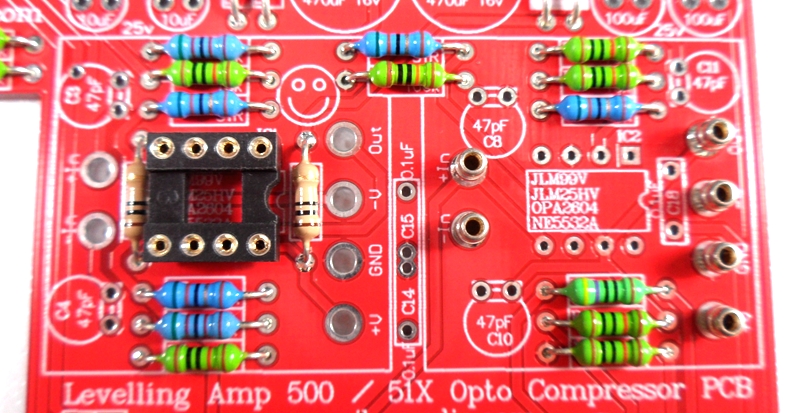
Note 2. R4 and R6 should be 5k1 NOT 10k as marked on the LA500 PCB. Edited correct overlay shown below as on all New LA500 kits
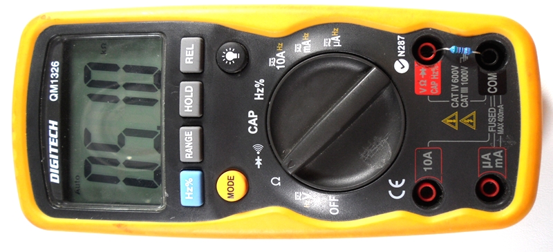
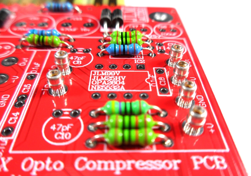
If you are not 100% with resistor colour codes use a multimeter to check values as you place the resistors
Fit all resistors at once bending the legs sightly outwards to hold them in place. This helps to make sure no resistors are put in the wrong position.
Notes and Errata
Note 1. Replacing R19 51R with new 33R give slightly better low frequencies response when using JLM111DC and JLM111DC compact output transformer.
In future kits we will be replacing all 51R with 33R. So R19 and R20 will both be changed to 33R on new PCBs.
Note 2. R4 and R6 should be 5k1 NOT 10k as marked on the LA500 PCB. Edited correct overlay shown below as on all New LA500 kits
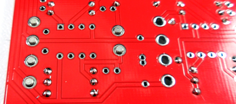
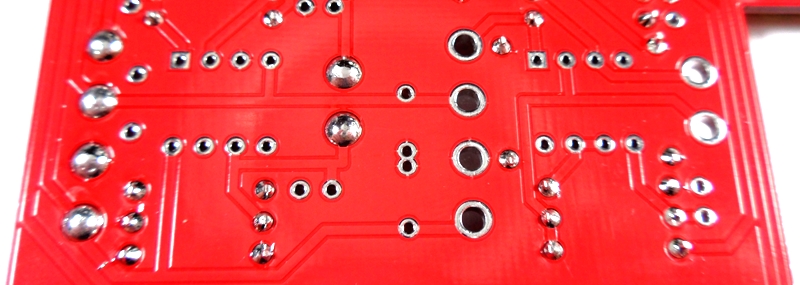
Solder all resistors while holding PCB firmly upside down on flat surface.
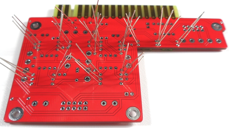
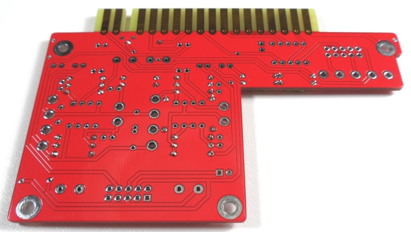
Cut all resistor legs off at top of the solder joint and double check no solder joints missed soldering.
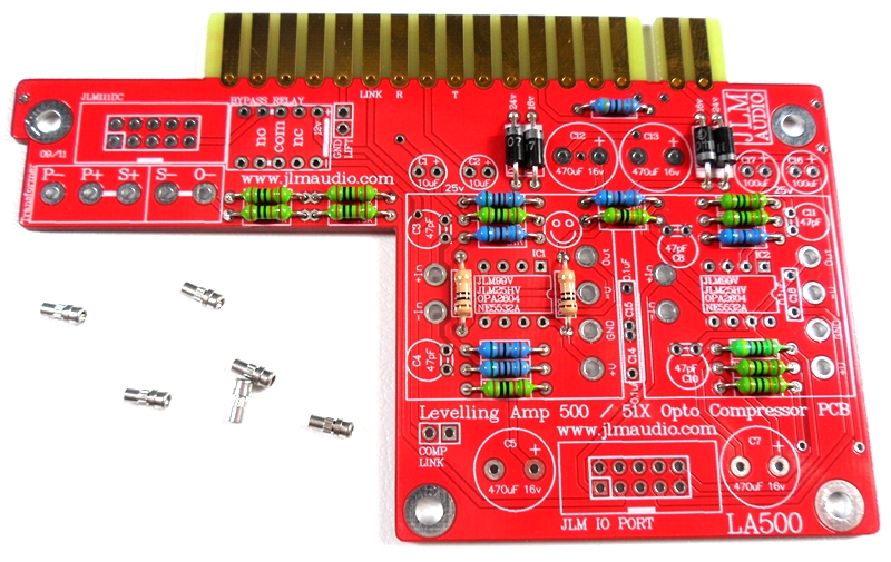
Fit the 4 x 1N4007 diodes. Diodes are POLARIZED and must go in with there stripe matching the strip on the PCB overlay.

Solder diodes in once you have checked there POLARITY is correct.

Fit 6 x 1mm sockets for 99v opamp. Do NOT press the sockets in. Just let them sit in the holes. Use a piece of cardboard to hold them in while turning the PCB over.
Solder 6 x 1mm sockets in place
Fit and solder DIP8 socket in other opamp position. Make sure the POLARIZED socket matches the PCB overlay.
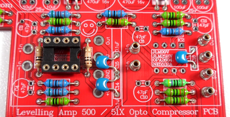
Fit and solder 3 x 0.1uF MONO caps in place. The 100nF caps are NOT Polarized so can go in either way around.
Caps should be marked 104 or 0.1u or 100n.
27th Dec 2015 a batch of kits has been packed with wrong value 102 1nF caps these will work fine for C14 & C15 but C18 will need to be 104 or 100nF or 0.1uF or larger. Can be any type of mono ceramic or MKT cap as it is only for the meter.
If C18 is smaller than 100nF you will not be able to calibrate the VU meter.
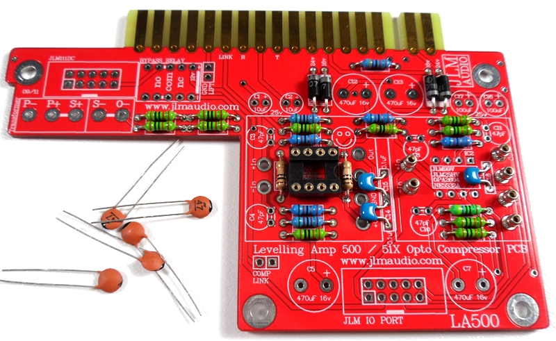
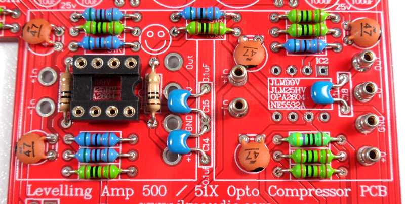
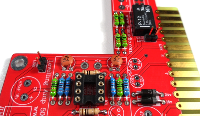
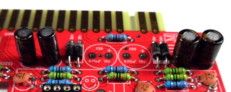
Fit 5 x 47pF ceramic caps in place. The 47pF caps are NOT Polarized so can go in either way around.
Fold 47pF caps down flat to PCB before soldering them.
Fit 12v relay in the POLARITY shown in the photo.
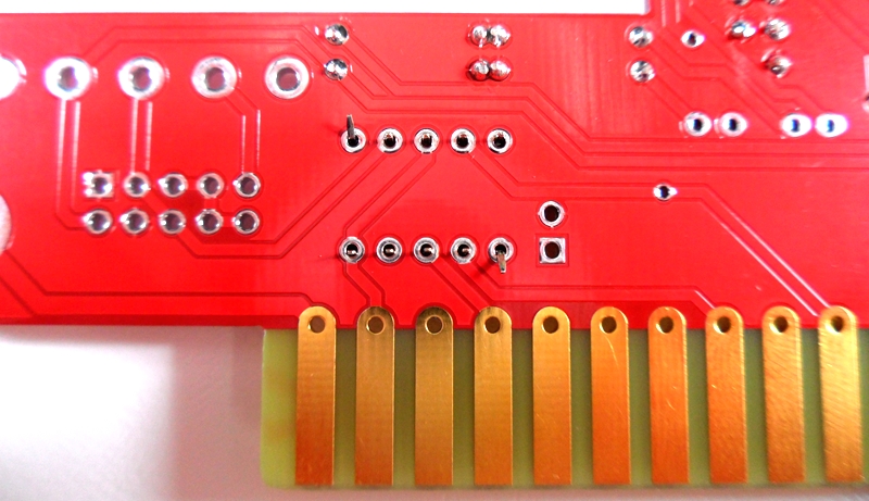
Bend 2 legs out to hold relay in place for soldering
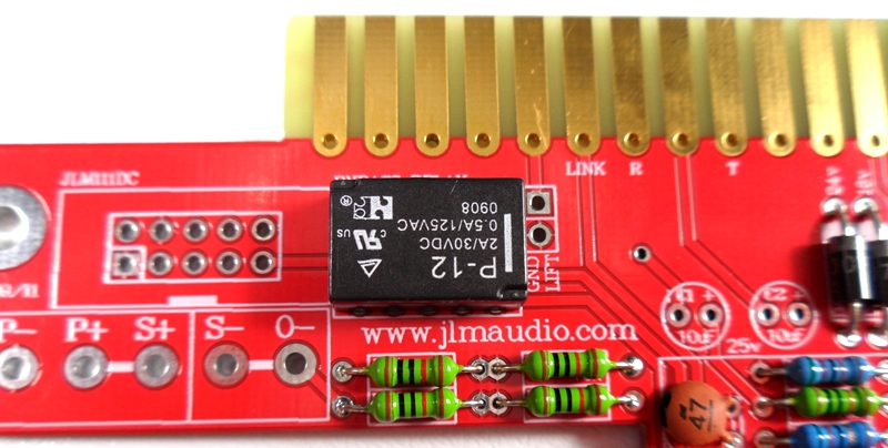
Solder relay in place once POLARITY has been checked
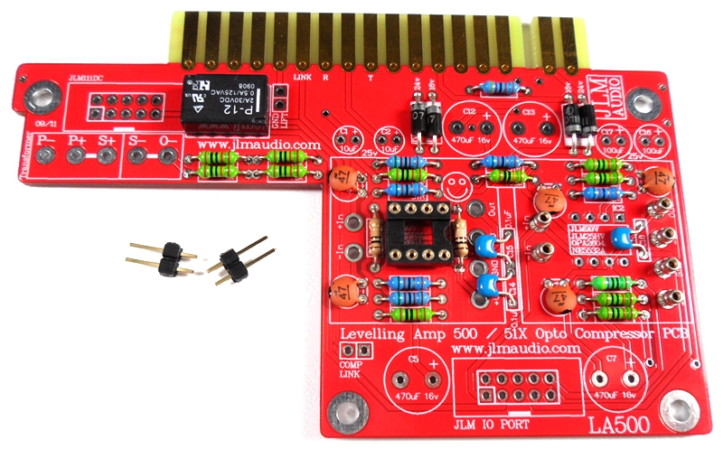
Fit and solder jumper pins in place
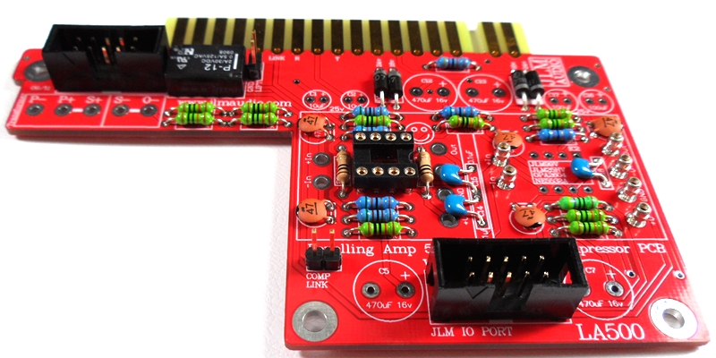
Fit and solder IDC headers in the POLARITY shown. Do not reverse. Triangle on header indicates pin 1 which is the square pad on the PCB.
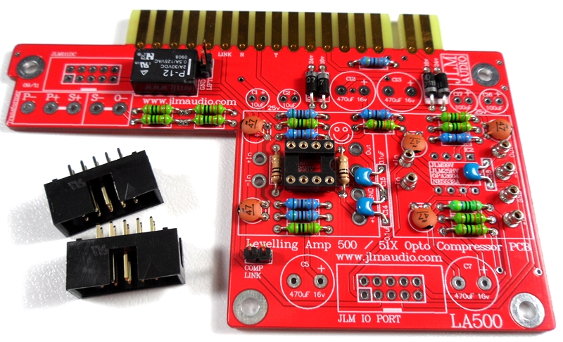
The front opening in the IDC headers should both now be facing as shown below.
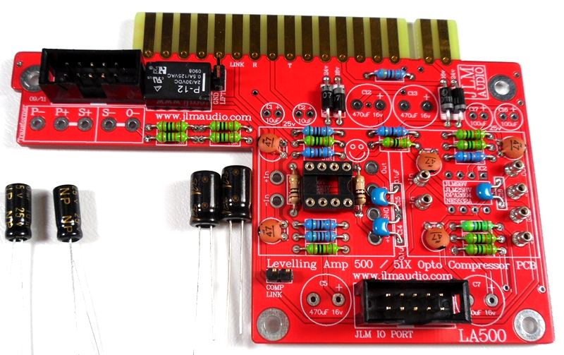
Fit and solder Electro caps to PCB. The 2 x 100uF caps are POLARIZED so must have there long positive leg fitted to + marked on PCB overlay.
2 x 10uF and 4 x 470uF caps are NON polar types so can go in either way around on the PCB.
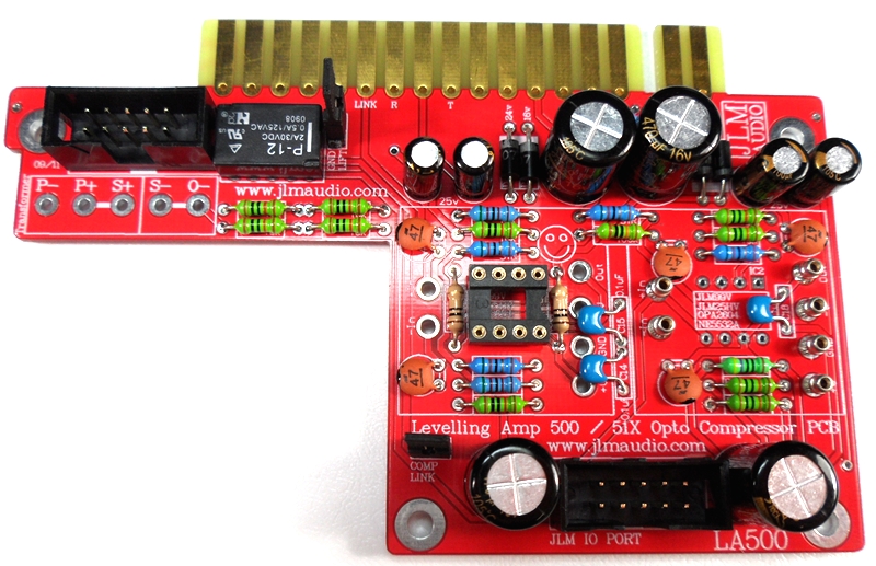
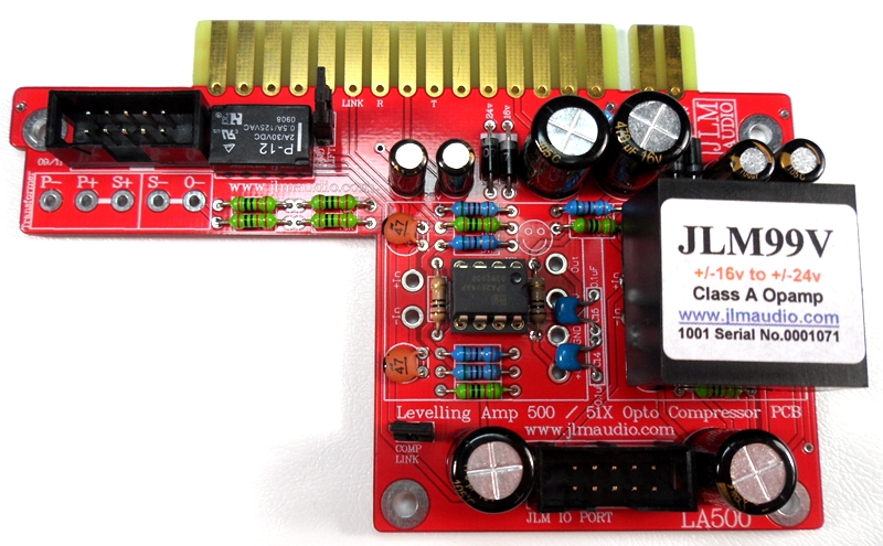
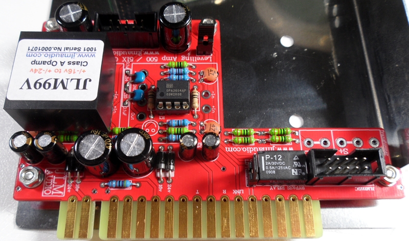
Fit OPA2604AP opamp in the correct POLARITY shown. 99v opamp can be fitted now or later. LA500 PCB is ready to go.
Put nuts and bolts etc back into zip lock bag the LA500 PCB kit came in to make sure they are not lost while you build the Small MAC PCB next.
MAC PCB Schematic with MAC alignment
http://www.jlmaudio.com/MAC/MACSCH.pdf
MAC PCB parts kit
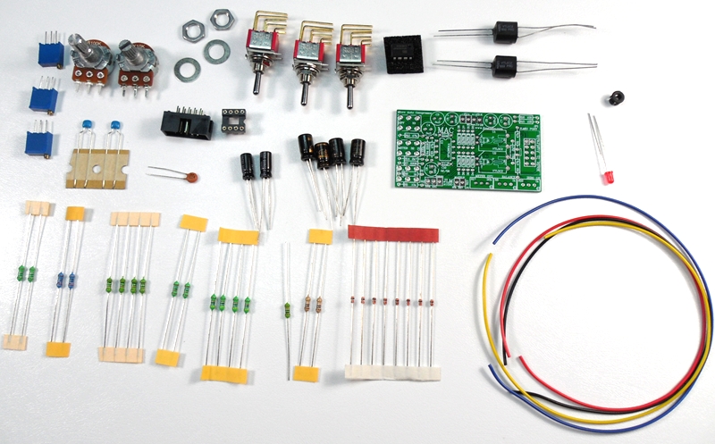
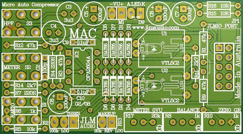
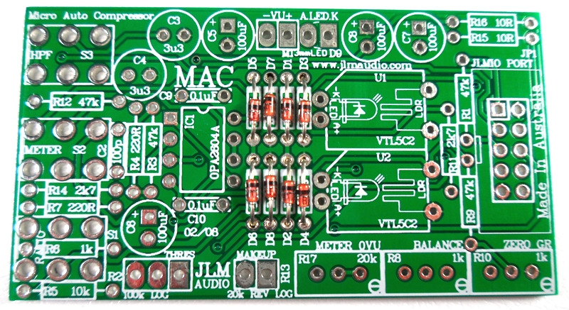
MAC PCB. PCB overlay has all values and there are no options.
so PCB can be assembled directly from overlay.
Notes and Errata (NEW RED COLOURED MAC PCB has all the below errors corrected)
JLM 34mm round VU meter needs D5 to D8 fitted.
LED D9 which is the meter led has A and K marking on MAC PCB are reversed . Rectangle Pad is A (+meter led)
R14 should be changed from 2k7 to 1k8 in all 500 series LA500 versions.
MAC kit now comes with all 1k trim pots replacing the 20k which makes setting the Meter 0VU easier
Fit all 8 x BAT85 diodes with there Cathode POLARIZED black stripe matching the white stripe on the MAC PCB overlay
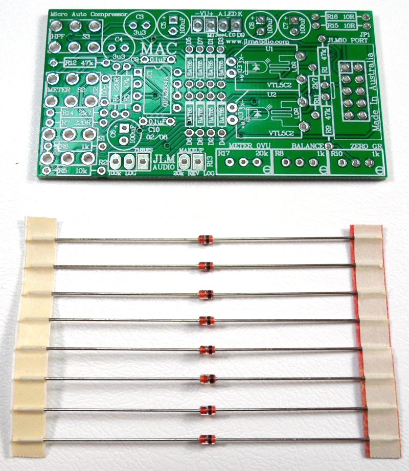
Solder all BAT85 diodes while holding PCB firmly upside down on flat surface. Make sure none of the center close pads are NOT shorted together.
Cut all diodes legs off at top of the solder joint and double check no solder joints missed soldering or are shorted together.
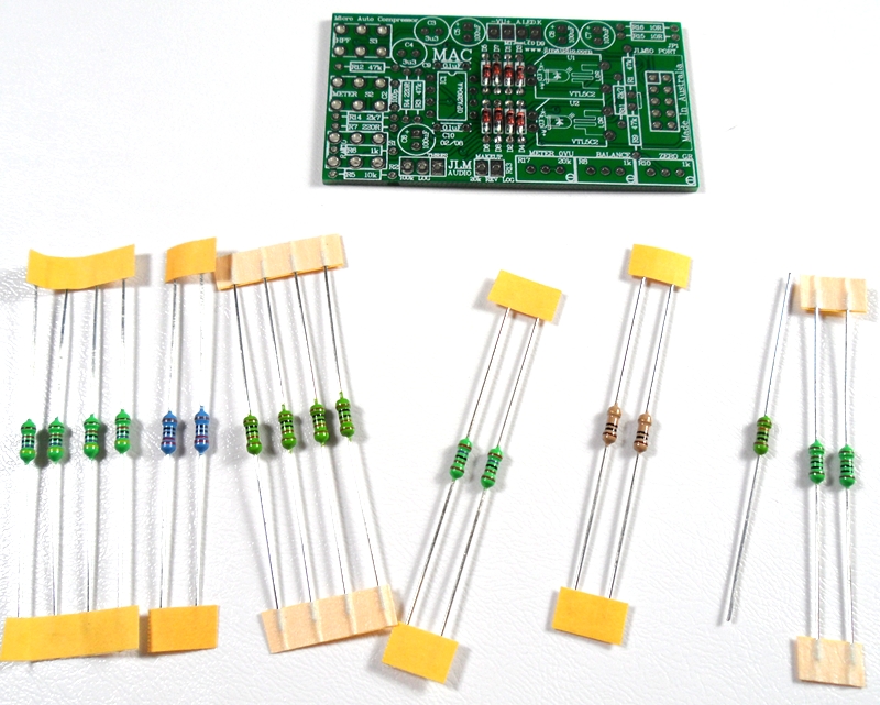
If you are not 100% with resistor colour codes use a multimeter to check values as you place the resistors
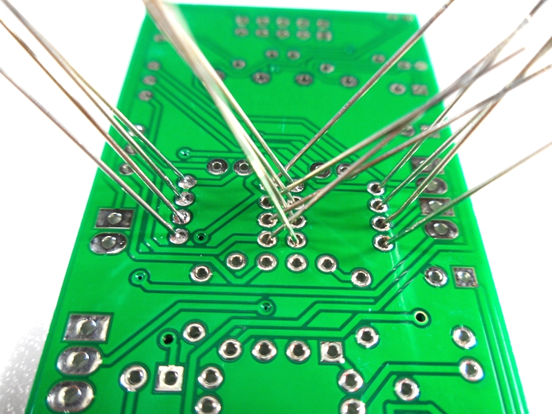
Fit all resistors at once bending the legs sightly outwards to hold them in place. This helps to make sure no resistors are put in the wrong position.
Solder all resistors while holding PCB firmly upside down on flat surface.
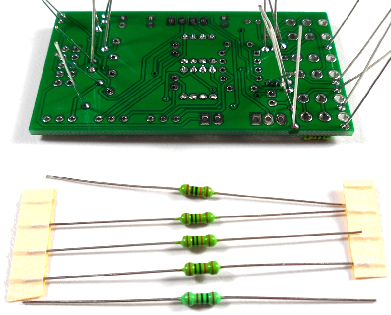
Cut all resistor legs off at top of the solder joint and double check no solder joints missed soldering.
Fit and solder DIP8 socket in other opamp position. Make sure the POLARIZED socket matches the PCB overlay.
Fit and solder 2 x 0.1uF MONO caps in place.
Fit 1 x 100pF ceramic caps in place.
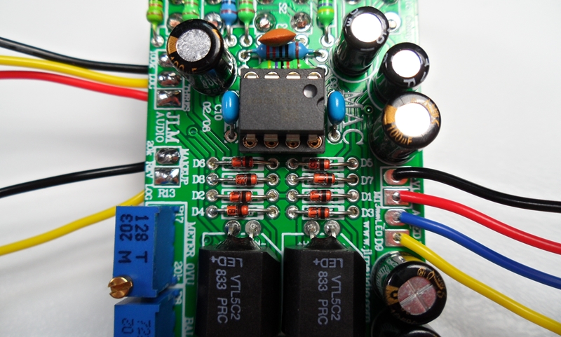
Newer builds Fit and solder NSL32 optos as shown below. Short legs are LED & Long legs are LDR on NSL-32.
The NSL32 Cathode has a dot marked on the case which goes to -K. Be gentle with the wire legs on the opto when shaping them for the PCB.
Note: If you are building a stereo matched pair. Fit the 2 optos in the plastic bag marked U1 into the U1 position on each separate PCB and same for the bag with the U2 pair.
If building just one comp use the 2 optos in the bag and either opto can go into U1 or U2.
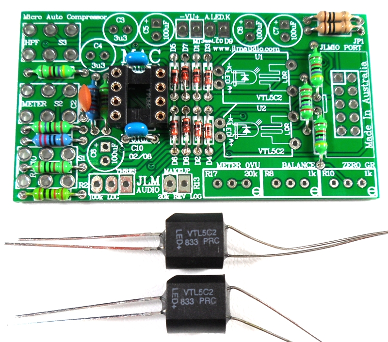
Older builds Fit and solder 2 x 5C2 optos in place.
Note: If you are building a stereo matched pair. Fit the 2 optos in the plastic bag marked U1 into the U1 position on each separate PCB and same for the bag with the U2 pair.
If building just one comp use the 2 optos in the bag and either opto can go into U1 or U2.

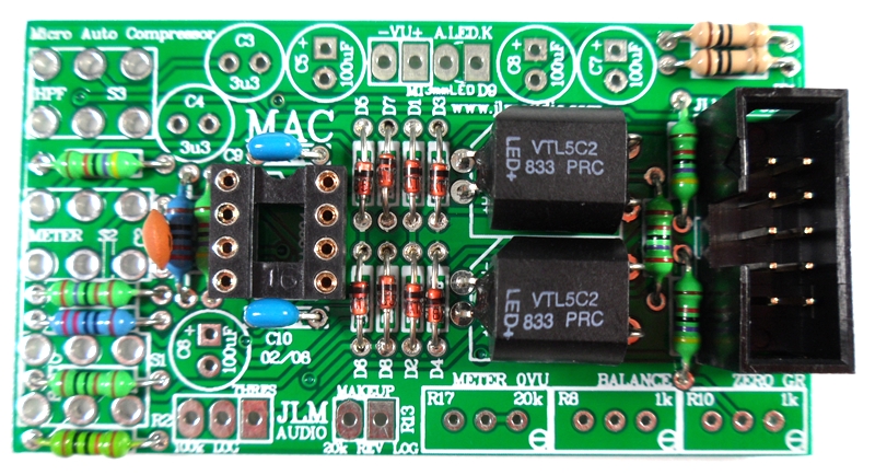
Fit and solder IDC headers in the POLARITY shown. Do not reverse. Triangle on header indicates pin 1 which is the square pad on the PCB.
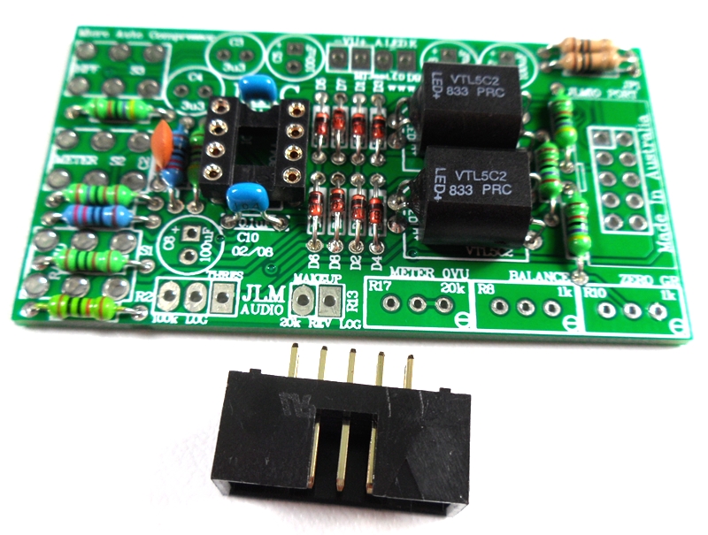
The front opening in the IDC headers should both now be facing as shown below.
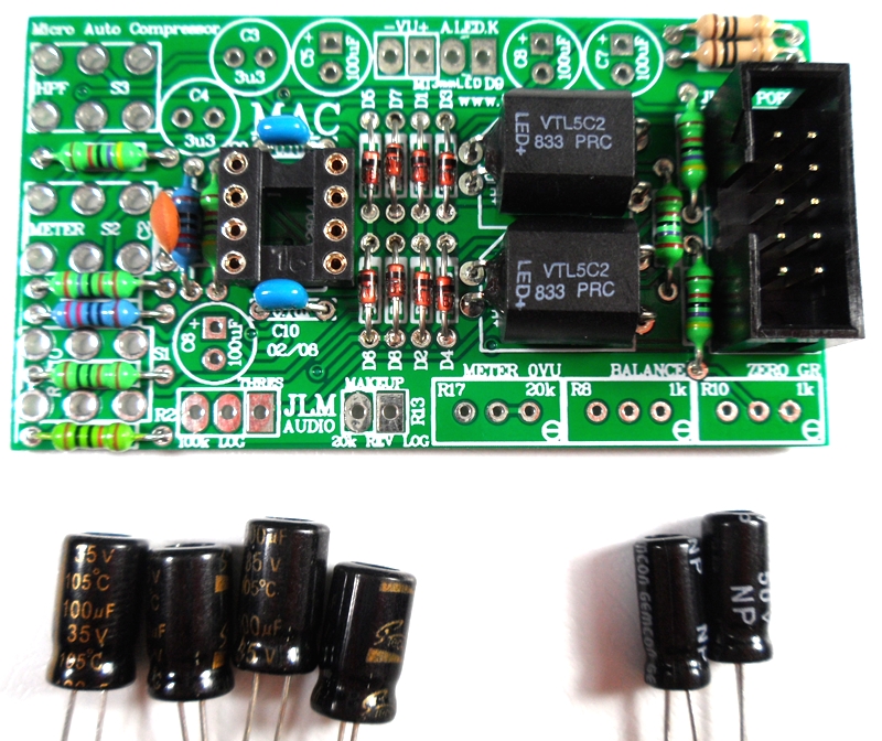
Fit and solder Electro caps to PCB. The 4 x 100uF caps are POLARIZED so must have there long positive leg fitted to + marked on PCB overlay.
2 x 3.3uF acaps are NON polar types so can go in either way around on the PCB.
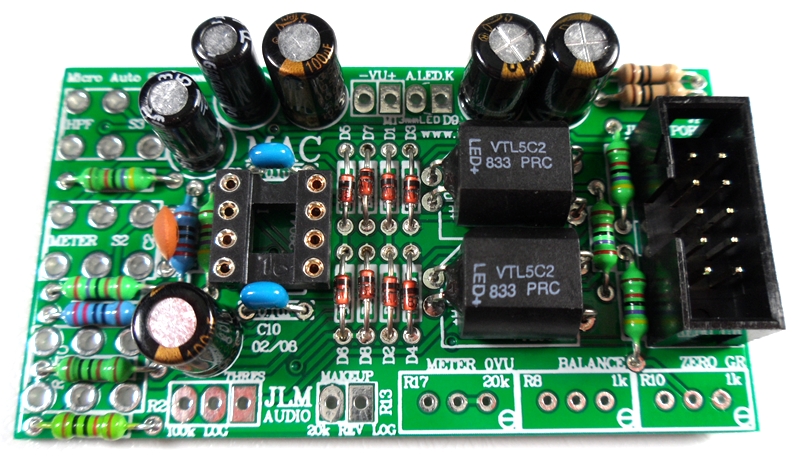
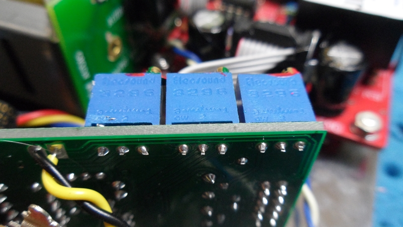
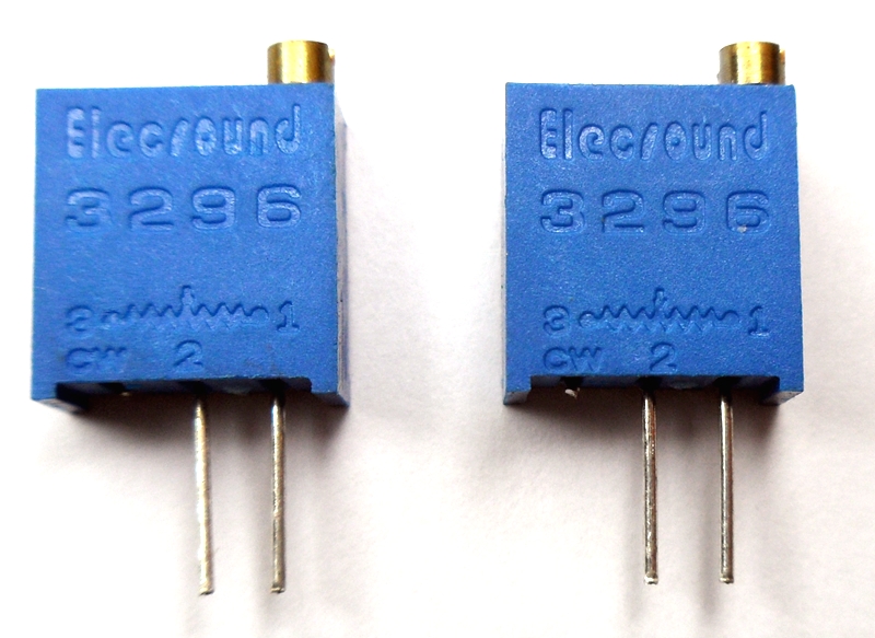
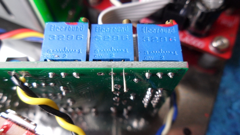
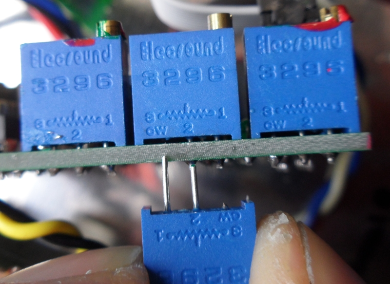
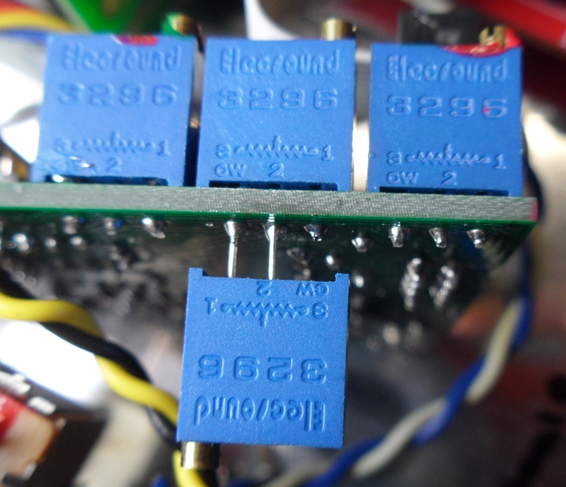
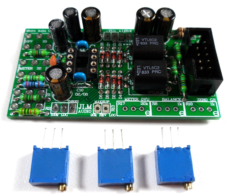
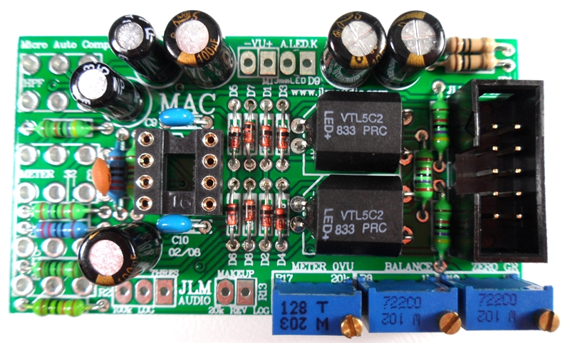
Fit and solder 3 trim pots as shown 20k = 203(replaced with 1k), 1k = 102 code. Place pot so trim screw is in corner shown below
Note MAC kit now comes with all 1k trim pots replacing the 20k which makes setting the Meter 0VU easier
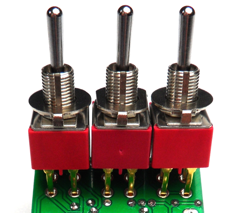
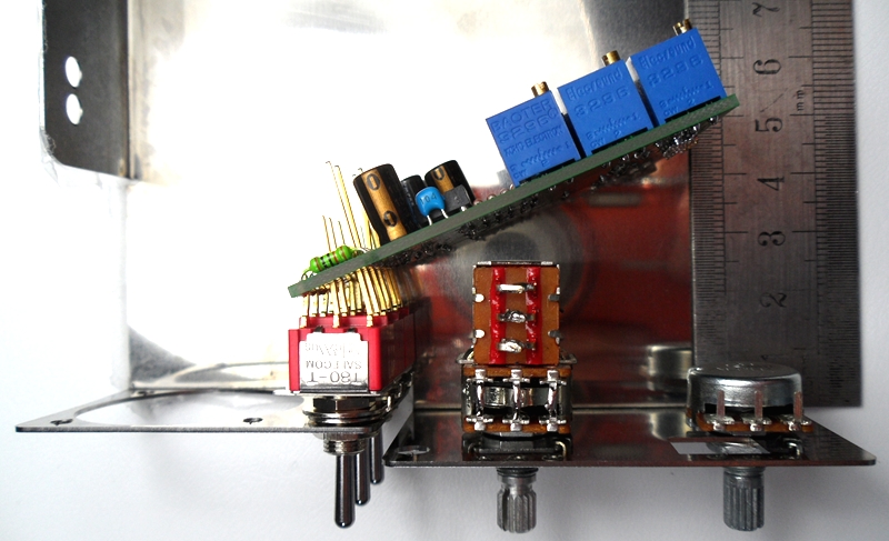
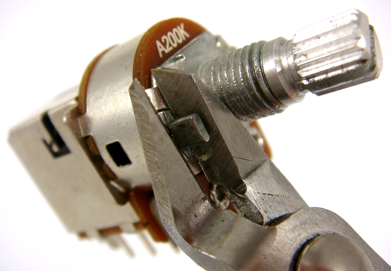
The three switches for the MAC when used with the LA500 have to have there 6 legs straightened with a set of small long nose pliers like below.
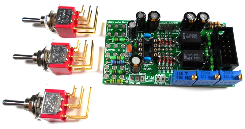
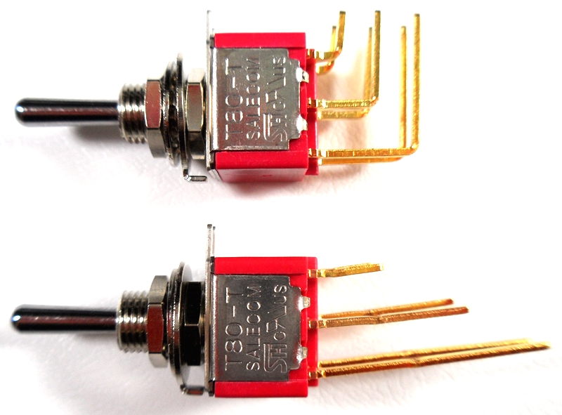
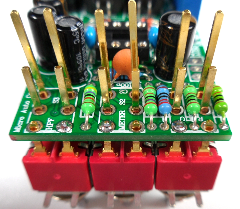
Align 3 switches in MAC PCB as shown with roughly 2mm of the short legs showing.
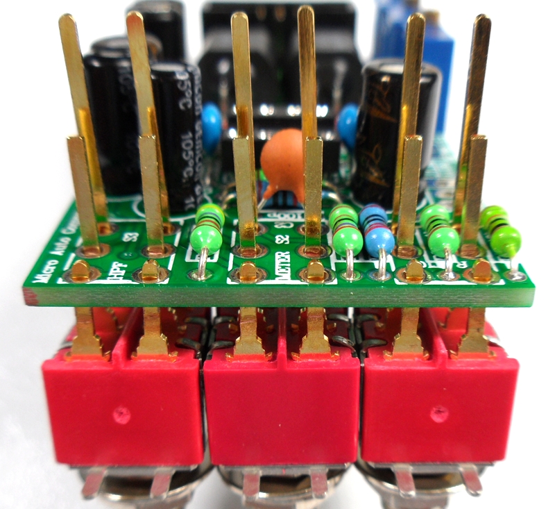
Solder one short leg on each switch to hold them in place.
Wind the back nut fully down on to the 3 switches. Fit the flat washers on next.
Cut the sides of the middle flat washers with sudecutters so it does not overlap the other washers.
Fit the 3 shake proof washers on next.
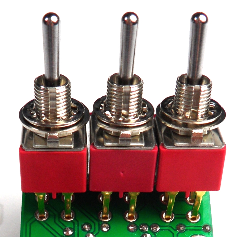
Fit the 3 switches into the holes in stainless steel bracket and do up the 3 nuts hand tight to hold the switches in place.
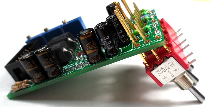
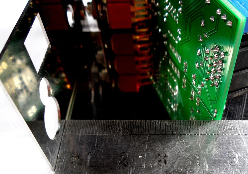
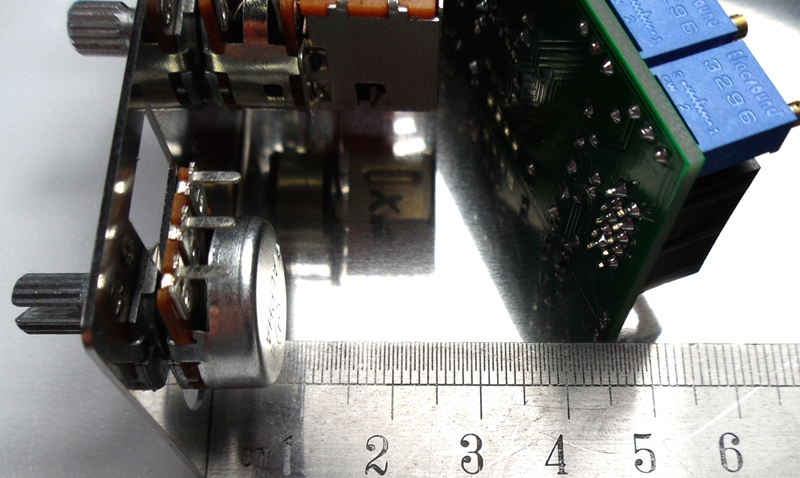
Push the bottom edge of the MAC PCB back under you have about 45mm from the front of the bracket to the bottom edge of the PCB.
This is to leave enough room for the Stereo LINK pull switch version of the threshold pot which is now standard in LA500 kit.
Solder all the switch legs you can reach easily while the switches are still fitted to the bracket.
Remove MAC PCB from bracket and finish soldering the switches and cut the switch legs down to the solder joint.
Cut the 4 wire colours provided into 75mm, 65mm and 45mm lengths and strip 5mm insulation of all wire ends.
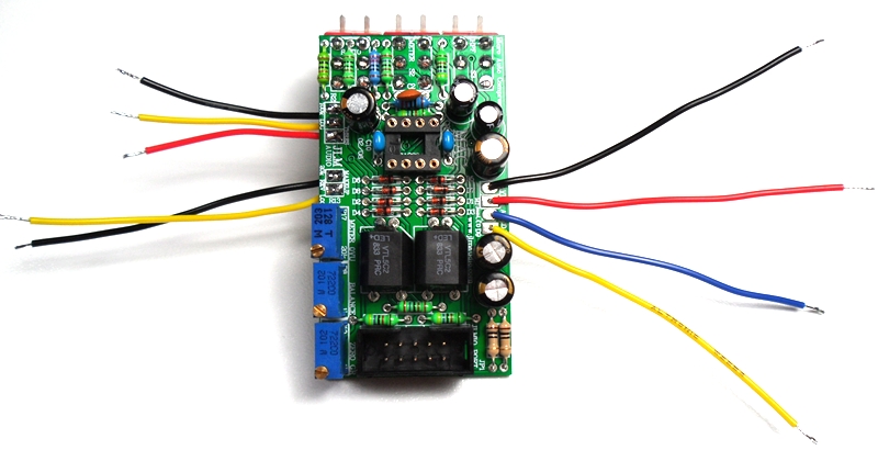
Twist wire strands together and tin with solder. Place colours as shown for meter in PCB and solder in place.

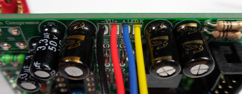
Wires for the meter go through the top of the PCB and are solder underneath the PCB.
Wires for the pots go though the bottom of the PCB and solder on the top of the PCB.
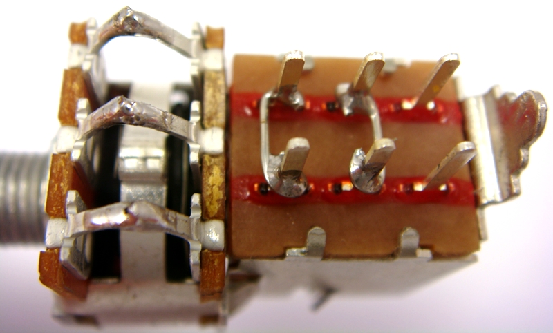
Cut off locate tabs on each pot with sidecutters
Fold the pot legs 90 degrees with log nose pliers and solder and link as shown below. Fit the 2 pots to the bracket and do up nuts hand tight.
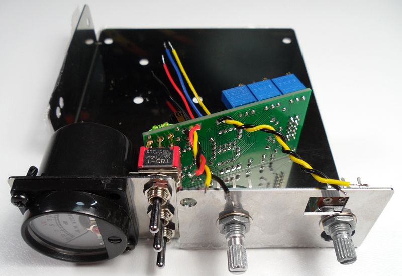
Fit the MAC PCB to the stainless bracket as before and do up the 3 nuts tight.
Fit the meter to the bracket using 2 of the black screws hand tight to hold it in place.
Use a piece of insulation tape to cover the opening in the pots so no solder can fall into them while soldering.
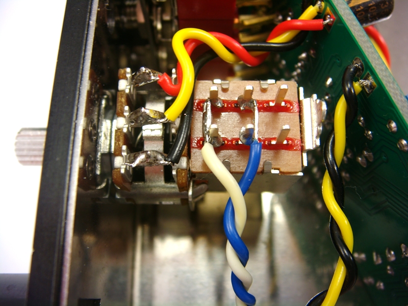
Tin the 6 pot terminals with solder. Yellow wire on makeup pot connects to both center and end terminal.
Twisting the coloured wires in there 3 groups and solder the wires as shown on to the meter and pots.
Remove insulating tape from pots.
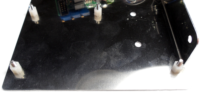
Fit the 4 x 12mm countersunk screws found in the LA500 PCB kit to the bracket and screw 6mm nylon spacers to them.
Nylon spacers have countersink on one side that should go down on to the bracket to take the protruding part of screws countersink.
Last chance to cut off 51X pins if converting the PCB to a 500 version.
Fit LA500 PCB and hold down with shakeproof washers and nuts provided in the LA500 PCB kit.
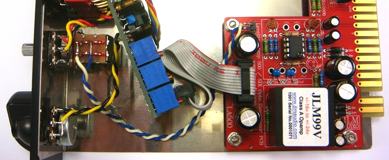
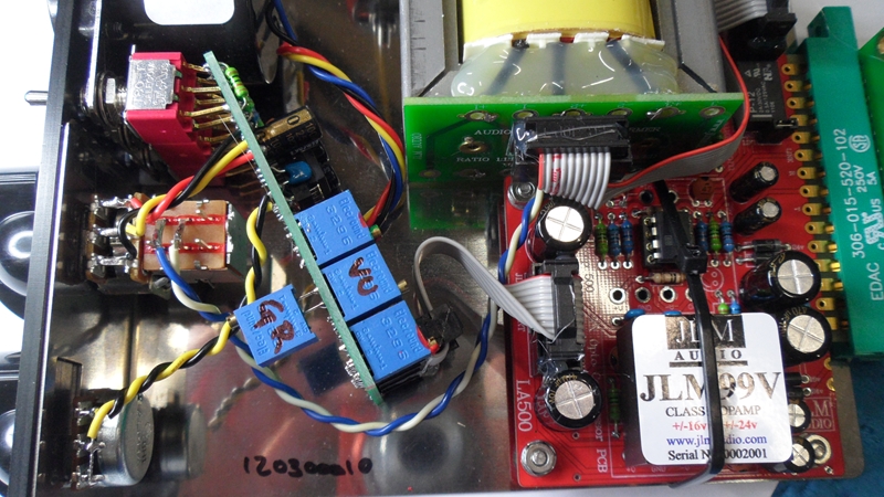
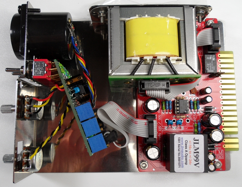
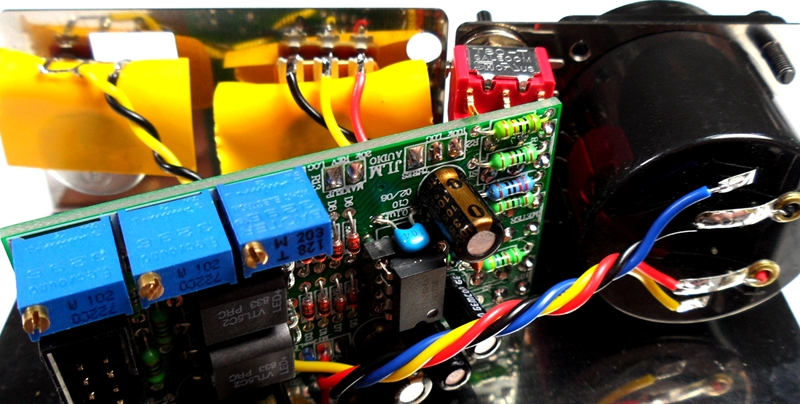
Fit ribbon cable provided to join the MAC PCB header to the JLMIO header as shown below.
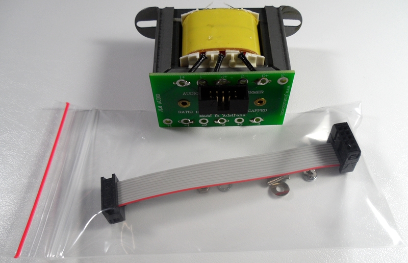
JLM111DC with wiring and hardware pack. Be warned do NOT touch the 3 yellow and black wires while handling the transformer as these are very thin wires and can easily be broken
(LATEST LA500 kits ship with the NEW JLM111DC COMPACT transformer with red top PCB to make it easier to slide into 500 racks.)
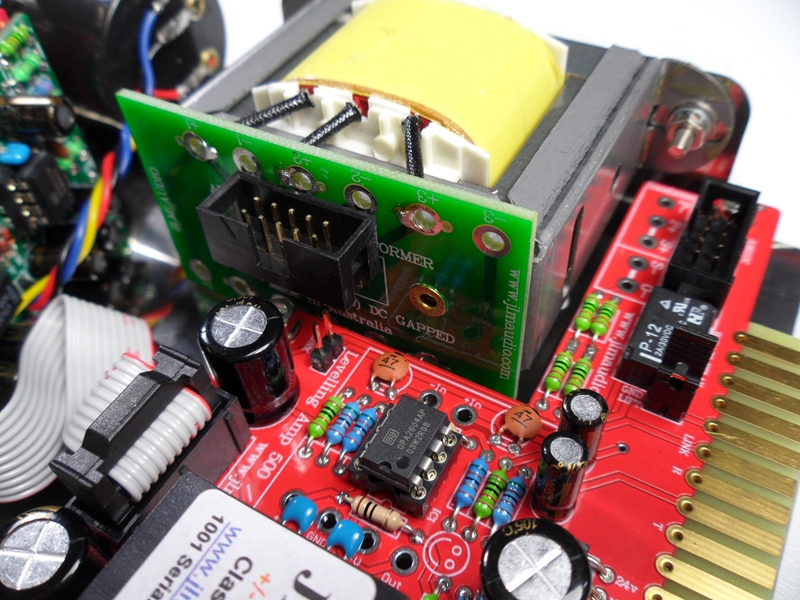
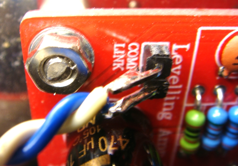
Remove link jumper if fitted and fit JLM111DC in place and bolt to the bracket.
(NEW JLM111DC COMPACT transformer with red top PCB needs 2 or 3 flat washers fitted between the LA500 support bracket and two transformer mounts)
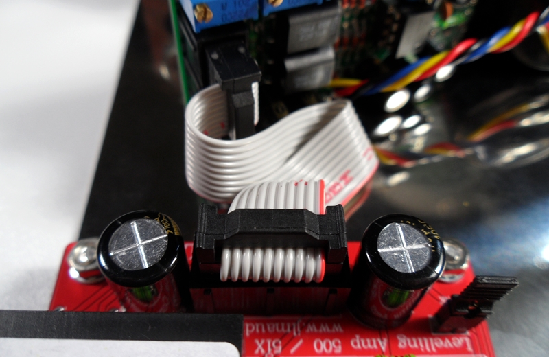
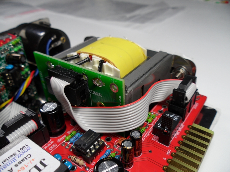
Fit ribbon cable between JLM111DC transformer and JLM111DC header on LA500 PCB.
Use shallow ribbon cable end with no cable relief clip fitted at the transformer end.
If you have a extender cable you can now test and align the LA500 before fitting the front panel and knobs.
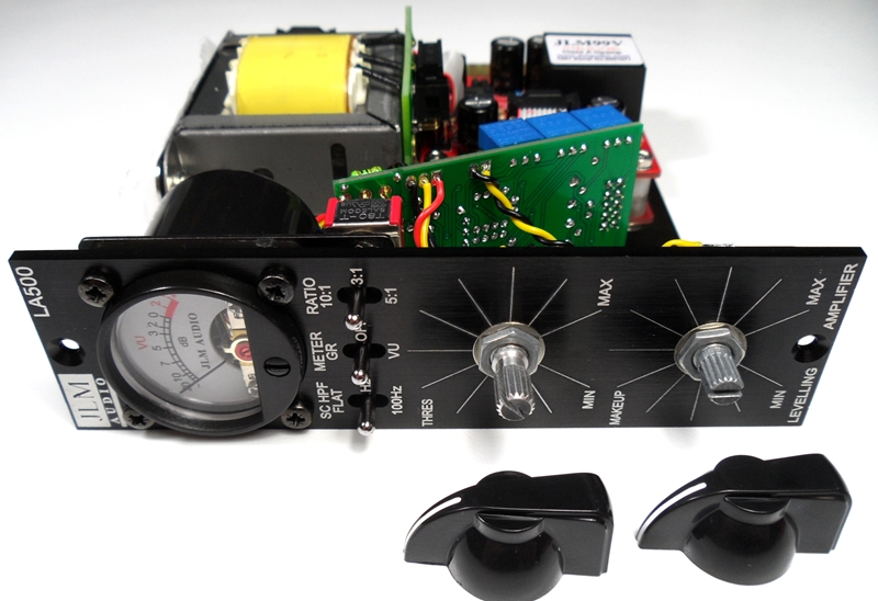
If you are going to test in the rack remove the pot nuts and washers and any screws holding the meter and fit the front panel.
Do up the pot nuts tight and screw the 4 meter screws in GENTLY and do NOT over-tighten them or you may strip the bracket thread. Lock-tight can be useful in a always traveling lunchbox to stop them shacking loose.
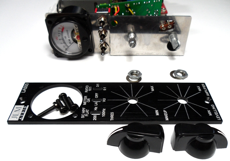
Best NOT to fit the chicken head knobs until you have fully aligned and tested the LA500.
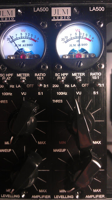
Compressor setup procedure
1. Set LA to Threshold pot fully CCW, Makeup pot to CCW. Ratio switch to 3:1, Meter switch to VU, HPF switch to FLAT.
2. Apply 1kHz tone to LA500 input at the reference level (usually +4dBM) you are going to use for 0VU.
3. Check output of the LA500A between pins 2 and 3 of the rack XLR (or pin 2 and 4 of the edge connector) for 1.23vac with multimeter.
If voltage not correct adjust 1kHz generator until correct. Or plug LA500A output into VU or PPM meter that is calibrated to a known level.
4. Adjust meter 0VU trim pot for desired level for 0VU on the meter.
5. Switch Meter switch to GR and adjust Zero GR trim pot for 0VU on meter.
6. Turn up Threshold pot until you have 5dB of compression on meter.
7. Switch Meter switch between GR and VU and adjust Balance trim pot until the same reading is seen in both GR and VU.
8. Your ready to rock.
For an idea on what the LA500 / MAC comp can do read this AT mag review here
New LA500 slow release attack mod info is http://www.jlmaudio.com/forum/viewtopic.php?f=2&t=253
LA500 recall sheet here
PDF of this build thread here
(PDF made by Eric Sills http://www.stonesouprec.com
LA500 Parts List
http://www.jlmaudio.com/LA500/LA500%20C ... 20list.txt
Complete LA500 kit with every part down to the last nut and bolt.
LA500 PCB schematic
http://www.jlmaudio.com/LA500/LA500%20S ... 120304.pdf
LA500 PCB kit
1. LA500 main pcb is a stripped down INX5 pcb so its overlay has the exact parts and values marked on it for the LA500 kit to make the build easy.
2. 51X and 500 compatible with 51X pins cut off. Kit fits all 500 and 51X racks and lunchboxes.
3. PCB automatically uses highest power available. +/-16v for 500 and +/-24v for 51X.
4. LA500 PCB also has mix buss out on pin 11 for Radial Workhorse racks.
LA500 PCB. For 500 series racks cut and file 51X pins off)
Notes and Errata
Note 1. Replacing R19 51R with new 33R give slightly better low frequencies response when using JLM111DC and JLM111DC compact output transformer.
In future kits we will be replacing all 51R with 33R. So R19 and R20 will both be changed to 33R on new PCBs.
Note 2. R4 and R6 should be 5k1 NOT 10k as marked on the LA500 PCB. Edited correct overlay shown below as on all New LA500 kits
If you are not 100% with resistor colour codes use a multimeter to check values as you place the resistors
Fit all resistors at once bending the legs sightly outwards to hold them in place. This helps to make sure no resistors are put in the wrong position.
Notes and Errata
Note 1. Replacing R19 51R with new 33R give slightly better low frequencies response when using JLM111DC and JLM111DC compact output transformer.
In future kits we will be replacing all 51R with 33R. So R19 and R20 will both be changed to 33R on new PCBs.
Note 2. R4 and R6 should be 5k1 NOT 10k as marked on the LA500 PCB. Edited correct overlay shown below as on all New LA500 kits
Solder all resistors while holding PCB firmly upside down on flat surface.
Cut all resistor legs off at top of the solder joint and double check no solder joints missed soldering.
Fit the 4 x 1N4007 diodes. Diodes are POLARIZED and must go in with there stripe matching the strip on the PCB overlay.
Solder diodes in once you have checked there POLARITY is correct.
Fit 6 x 1mm sockets for 99v opamp. Do NOT press the sockets in. Just let them sit in the holes. Use a piece of cardboard to hold them in while turning the PCB over.
Solder 6 x 1mm sockets in place
Fit and solder DIP8 socket in other opamp position. Make sure the POLARIZED socket matches the PCB overlay.
Fit and solder 3 x 0.1uF MONO caps in place. The 100nF caps are NOT Polarized so can go in either way around.
Caps should be marked 104 or 0.1u or 100n.
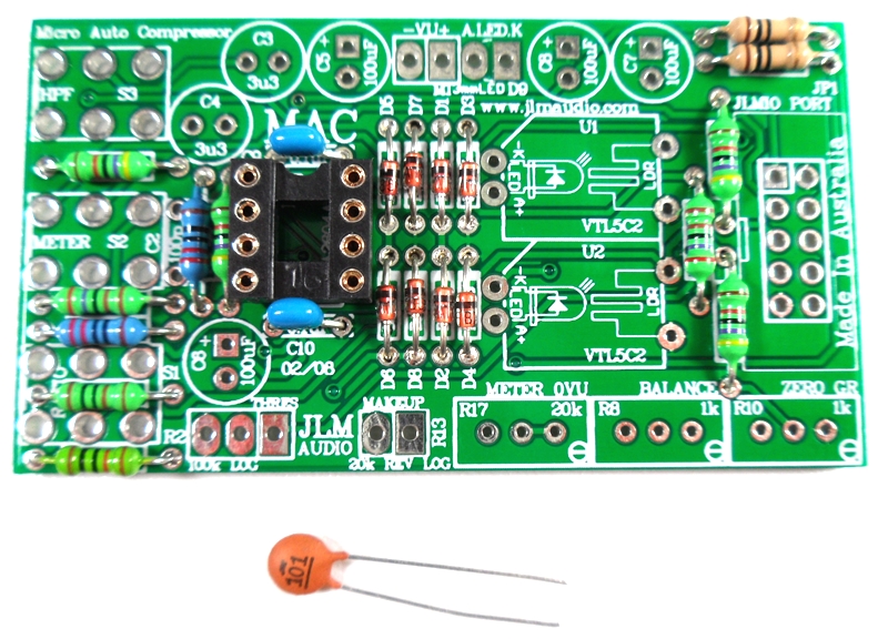
27th Dec 2015 a batch of kits has been packed with wrong value 102 1nF caps these will work fine for C14 & C15 but C18 will need to be 104 or 100nF or 0.1uF or larger. Can be any type of mono ceramic or MKT cap as it is only for the meter.
If C18 is smaller than 100nF you will not be able to calibrate the VU meter.
Fit 5 x 47pF ceramic caps in place. The 47pF caps are NOT Polarized so can go in either way around.
Fold 47pF caps down flat to PCB before soldering them.
Fit 12v relay in the POLARITY shown in the photo.
Bend 2 legs out to hold relay in place for soldering
Solder relay in place once POLARITY has been checked
Fit and solder jumper pins in place
Fit and solder IDC headers in the POLARITY shown. Do not reverse. Triangle on header indicates pin 1 which is the square pad on the PCB.
The front opening in the IDC headers should both now be facing as shown below.
Fit and solder Electro caps to PCB. The 2 x 100uF caps are POLARIZED so must have there long positive leg fitted to + marked on PCB overlay.
2 x 10uF and 4 x 470uF caps are NON polar types so can go in either way around on the PCB.
Fit OPA2604AP opamp in the correct POLARITY shown. 99v opamp can be fitted now or later. LA500 PCB is ready to go.
Put nuts and bolts etc back into zip lock bag the LA500 PCB kit came in to make sure they are not lost while you build the Small MAC PCB next.
MAC PCB Schematic with MAC alignment
http://www.jlmaudio.com/MAC/MACSCH.pdf
MAC PCB parts kit
MAC PCB. PCB overlay has all values and there are no options.
so PCB can be assembled directly from overlay.
Notes and Errata (NEW RED COLOURED MAC PCB has all the below errors corrected)
JLM 34mm round VU meter needs D5 to D8 fitted.
LED D9 which is the meter led has A and K marking on MAC PCB are reversed . Rectangle Pad is A (+meter led)
R14 should be changed from 2k7 to 1k8 in all 500 series LA500 versions.
MAC kit now comes with all 1k trim pots replacing the 20k which makes setting the Meter 0VU easier
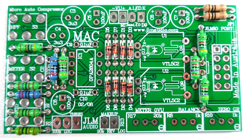
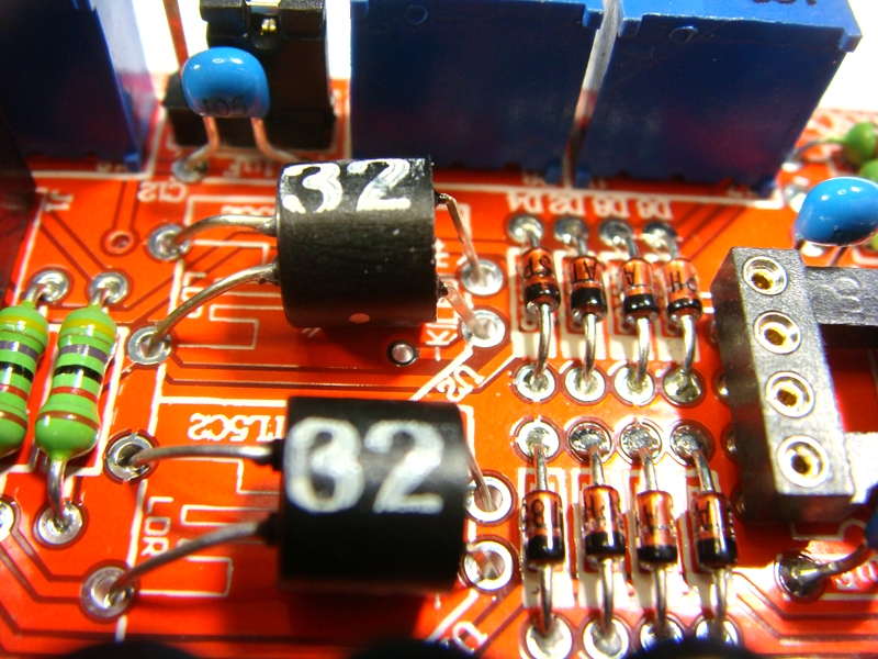
Fit all 8 x BAT85 diodes with there Cathode POLARIZED black stripe matching the white stripe on the MAC PCB overlay
Solder all BAT85 diodes while holding PCB firmly upside down on flat surface. Make sure none of the center close pads are NOT shorted together.
Cut all diodes legs off at top of the solder joint and double check no solder joints missed soldering or are shorted together.
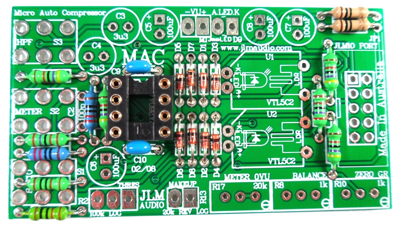
If you are not 100% with resistor colour codes use a multimeter to check values as you place the resistors
Fit all resistors at once bending the legs sightly outwards to hold them in place. This helps to make sure no resistors are put in the wrong position.
Solder all resistors while holding PCB firmly upside down on flat surface.
Cut all resistor legs off at top of the solder joint and double check no solder joints missed soldering.
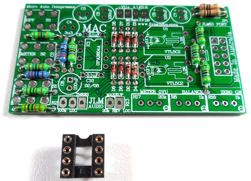
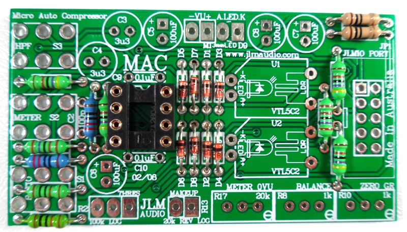
Fit and solder DIP8 socket in other opamp position. Make sure the POLARIZED socket matches the PCB overlay.
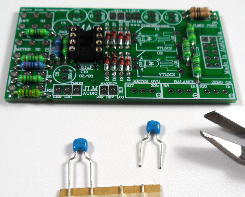
Fit and solder 2 x 0.1uF MONO caps in place.
Fit 1 x 100pF ceramic caps in place.
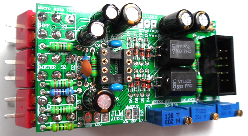
Newer builds Fit and solder NSL32 optos as shown below. Short legs are LED & Long legs are LDR on NSL-32.
The NSL32 Cathode has a dot marked on the case which goes to -K. Be gentle with the wire legs on the opto when shaping them for the PCB.
Note: If you are building a stereo matched pair. Fit the 2 optos in the plastic bag marked U1 into the U1 position on each separate PCB and same for the bag with the U2 pair.
If building just one comp use the 2 optos in the bag and either opto can go into U1 or U2.
Older builds Fit and solder 2 x 5C2 optos in place.
Note: If you are building a stereo matched pair. Fit the 2 optos in the plastic bag marked U1 into the U1 position on each separate PCB and same for the bag with the U2 pair.
If building just one comp use the 2 optos in the bag and either opto can go into U1 or U2.
Fit and solder IDC headers in the POLARITY shown. Do not reverse. Triangle on header indicates pin 1 which is the square pad on the PCB.
The front opening in the IDC headers should both now be facing as shown below.
Fit and solder Electro caps to PCB. The 4 x 100uF caps are POLARIZED so must have there long positive leg fitted to + marked on PCB overlay.
2 x 3.3uF acaps are NON polar types so can go in either way around on the PCB.
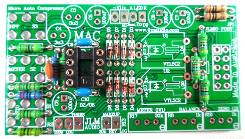
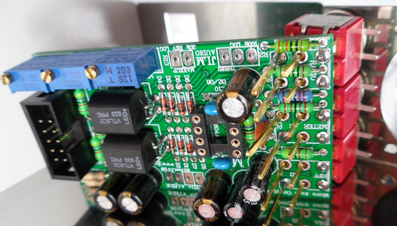
Fit and solder 3 trim pots as shown 20k = 203(replaced with 1k), 1k = 102 code. Place pot so trim screw is in corner shown below
Note MAC kit now comes with all 1k trim pots replacing the 20k which makes setting the Meter 0VU easier
The three switches for the MAC when used with the LA500 have to have there 6 legs straightened with a set of small long nose pliers like below.
Align 3 switches in MAC PCB as shown with roughly 2mm of the short legs showing.
Solder one short leg on each switch to hold them in place.
Wind the back nut fully down on to the 3 switches. Fit the flat washers on next.
Cut the sides of the middle flat washers with sudecutters so it does not overlap the other washers.
Fit the 3 shake proof washers on next.
Fit the 3 switches into the holes in stainless steel bracket and do up the 3 nuts hand tight to hold the switches in place.
Push the bottom edge of the MAC PCB back under you have about 45mm from the front of the bracket to the bottom edge of the PCB.
This is to leave enough room for the Stereo LINK pull switch version of the threshold pot which is now standard in LA500 kit.
Solder all the switch legs you can reach easily while the switches are still fitted to the bracket.
Remove MAC PCB from bracket and finish soldering the switches and cut the switch legs down to the solder joint.
Cut the 4 wire colours provided into 75mm, 65mm and 45mm lengths and strip 5mm insulation of all wire ends.
Twist wire strands together and tin with solder. Place colours as shown for meter in PCB and solder in place.
Wires for the meter go through the top of the PCB and are solder underneath the PCB.
Wires for the pots go though the bottom of the PCB and solder on the top of the PCB.
Cut off locate tabs on each pot with sidecutters
Fold the pot legs 90 degrees with log nose pliers and solder and link as shown below. Fit the 2 pots to the bracket and do up nuts hand tight.
Fit the MAC PCB to the stainless bracket as before and do up the 3 nuts tight.
Fit the meter to the bracket using 2 of the black screws hand tight to hold it in place.
Use a piece of insulation tape to cover the opening in the pots so no solder can fall into them while soldering.
Tin the 6 pot terminals with solder. Yellow wire on makeup pot connects to both center and end terminal.
Twisting the coloured wires in there 3 groups and solder the wires as shown on to the meter and pots.
Remove insulating tape from pots.
Fit the 4 x 12mm countersunk screws found in the LA500 PCB kit to the bracket and screw 6mm nylon spacers to them.
Nylon spacers have countersink on one side that should go down on to the bracket to take the protruding part of screws countersink.
Last chance to cut off 51X pins if converting the PCB to a 500 version.
Fit LA500 PCB and hold down with shakeproof washers and nuts provided in the LA500 PCB kit.
Fit ribbon cable provided to join the MAC PCB header to the JLMIO header as shown below.
JLM111DC with wiring and hardware pack. Be warned do NOT touch the 3 yellow and black wires while handling the transformer as these are very thin wires and can easily be broken
(LATEST LA500 kits ship with the NEW JLM111DC COMPACT transformer with red top PCB to make it easier to slide into 500 racks.)
Remove link jumper if fitted and fit JLM111DC in place and bolt to the bracket.
(NEW JLM111DC COMPACT transformer with red top PCB needs 2 or 3 flat washers fitted between the LA500 support bracket and two transformer mounts)
Fit ribbon cable between JLM111DC transformer and JLM111DC header on LA500 PCB.
Use shallow ribbon cable end with no cable relief clip fitted at the transformer end.
If you have a extender cable you can now test and align the LA500 before fitting the front panel and knobs.
If you are going to test in the rack remove the pot nuts and washers and any screws holding the meter and fit the front panel.
Do up the pot nuts tight and screw the 4 meter screws in GENTLY and do NOT over-tighten them or you may strip the bracket thread. Lock-tight can be useful in a always traveling lunchbox to stop them shacking loose.
Best NOT to fit the chicken head knobs until you have fully aligned and tested the LA500.
Compressor setup procedure
1. Set LA to Threshold pot fully CCW, Makeup pot to CCW. Ratio switch to 3:1, Meter switch to VU, HPF switch to FLAT.
2. Apply 1kHz tone to LA500 input at the reference level (usually +4dBM) you are going to use for 0VU.
3. Check output of the LA500A between pins 2 and 3 of the rack XLR (or pin 2 and 4 of the edge connector) for 1.23vac with multimeter.
If voltage not correct adjust 1kHz generator until correct. Or plug LA500A output into VU or PPM meter that is calibrated to a known level.
4. Adjust meter 0VU trim pot for desired level for 0VU on the meter.
5. Switch Meter switch to GR and adjust Zero GR trim pot for 0VU on meter.
6. Turn up Threshold pot until you have 5dB of compression on meter.
7. Switch Meter switch between GR and VU and adjust Balance trim pot until the same reading is seen in both GR and VU.
8. Your ready to rock.
 \
\