BA500v2 Mic Pre Amp BUILD THREAD 500/51X

Support for JLM Audio Kits

Moderator: Joe Malone

User avatar
Joe Malone
Site Admin
Posts: 2062
Joined: Wed Jan 24, 2007 11:35 pm
Location: Brisbane, Australia
Contact:

BA500v2 Mic Pre Amp BUILD THREAD 500/51X

Post by Joe Malone »

BA500v2 Mic Pre Amp BUILD THREAD 500/51X

Please feel free to ask for any extra info you need while building on this thread so I can add it here.

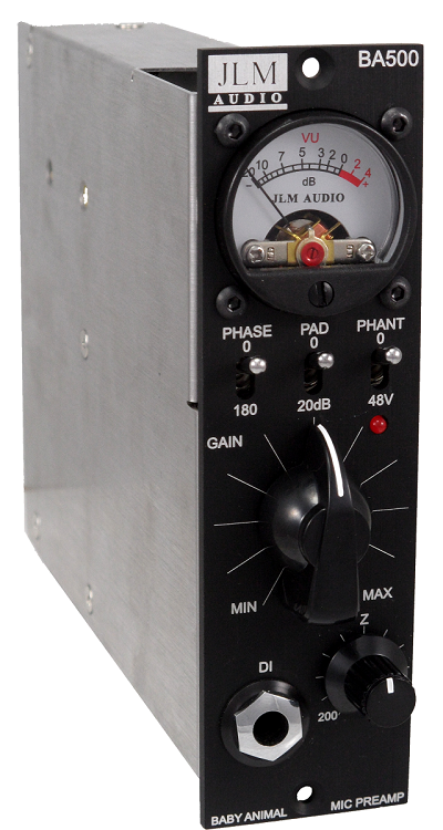
The BA500v2 is a 500/51x version of our well know Baby Animal mic pre.
Image

BA500v2 PCB build map
http://jlmaudio.com/builds/maps/BA500_map.html

GB500v2 PCB build map
http://jlmaudio.com/builds/maps/BA500_G ... n_map.html

FETDI500v2 PCB build map
http://jlmaudio.com/builds/maps/BA500_FETDI_map.html

If you are not 100% with resistor colour codes use a multimeter to check values as you place the resistors
Image

Big Vocals and acoustic instruments mic pre (Cut down version of our Dual99v)
VTX input transformer + JLM99v opamp + JLM111PCB output transformer.

Fat Drums, Bass & synth mic pre
JLM14 input transformer + JLM99v opamp + JLM111PCB output transformer.

API style mic pre
JLM14 input transformer (wired 1:8) + Twenty 5 Twenty SMD opamp + JLM2503 output transformer.

Chart of variable parts
RPAD Normally = 120R but can be made smaller in value for greater than 20dB PAD or larger for less than 20dB PAD
RLoad for JLM14 = 2k2 and Z pot 50k (front & back pot legs joined), for VTX = 10k and Z pot 100k (use back pot legs only)
CLoad can be not fitted or up to 390pF in value depending on the opamp used has stability problems.
Ratio Pads not used for JLM14 or VTX leave blank. Only API2622, JE-115 etc
Phase pads These are only needed/used if fitting API2622, JE-115 input transformer etc.

Click on images to enlarge
Toggles.jpg
Toggles 2.jpg
Toggles 3.jpg
Toggles 4.jpg
Toggles Meter & Pots.jpg
Cut Cable inchs.jpg
Cut Cable mm.jpg
Cut cables & solder.jpg
BA500v2 pot wiring colours.jpg
Pot wiring for JLM14.jpg
BA500v2 front detail.jpg
Toggle switch & LED detail.jpg
BA500v2 front angle.jpg
BA500v2 back angle.jpg
BA500v2 side.jpg
BA500v2 angle with DI fitted.jpeg
10 pin header on GO500v2 pcb no DI.jpg
You do not have the required permissions to view the files attached to this post.
Joe :-)
JLM Audio
Capturing Audio without Injury

kellyad33
Posts: 6
Joined: Sun Nov 28, 2021 2:27 pm

Re: BA500v2 Mic Pre Amp BUILD THREAD 500/51X

Post by kellyad33 »

Just building this BA500v2 now and didn't realise there wasn't a complete build thread for this version.
The build maps are great, and the base build seemed simple and complete.

But I wasn't sure with some of the Go Between Build Map ...What do I do when I get to:
CZbl See chart
Ratio See chart
Phase pads See chart
What chart is it talking about?

Also it doesn't seem clear on the wiring for the assembly. I've tried to make it out from the assembled pics but can't quite see.

User avatar
Joe Malone
Site Admin
Posts: 2062
Joined: Wed Jan 24, 2007 11:35 pm
Location: Brisbane, Australia
Contact:

Re: BA500v2 Mic Pre Amp BUILD THREAD 500/51X

Post by Joe Malone »

kellyad33 wrote:
Mon Nov 29, 2021 12:00 pm
Just building this BA500v2 now and didn't realise there wasn't a complete build thread for this version.
The build maps are great, and the base build seemed simple and complete.

But I wasn't sure with some of the Go Between Build Map ...What do I do when I get to:
CZbl See chart
Ratio See chart
Phase pads See chart
What chart is it talking about?

Also it doesn't seem clear on the wiring for the assembly. I've tried to make it out from the assembled pics but can't quite see.
Reload this page to see the updated page and let me know if you need any more info. Chart info is just under the multimeter image
Joe :-)
JLM Audio
Capturing Audio without Injury

kellyad33
Posts: 6
Joined: Sun Nov 28, 2021 2:27 pm

Re: BA500v2 Mic Pre Amp BUILD THREAD 500/51X

Post by kellyad33 »

Ok thanks that's great.
One more question ...for the 500 series chassis, do I still cut off the extra pins on the main PCB? (the 51X pins).
I'm assuming the intent is to look through the older build for any additional instructions? Like following the VU meter calibration instructions from the older version notes too.

If you were wanting to make it extra straight forward for people doing the BA500V2 build (and so it's all in one place) you could add the calibration and the trimming of the extra pins if this is all the same.

I'll see if I can finish the build tomorrow and let you know if there's anything else that isn't clear for a novice like myself.

kellyad33
Posts: 6
Joined: Sun Nov 28, 2021 2:27 pm

Re: BA500v2 Mic Pre Amp BUILD THREAD 500/51X

Post by kellyad33 »

Great build though, the new layout is very neat and easy to follow

User avatar
Joe Malone
Site Admin
Posts: 2062
Joined: Wed Jan 24, 2007 11:35 pm
Location: Brisbane, Australia
Contact:

Re: BA500v2 Mic Pre Amp BUILD THREAD 500/51X

Post by Joe Malone »

kellyad33 wrote:
Tue Nov 30, 2021 11:19 am
Ok thanks that's great.
One more question ...for the 500 series chassis, do I still cut off the extra pins on the main PCB? (the 51X pins).
I'm assuming the intent is to look through the older build for any additional instructions? Like following the VU meter calibration instructions from the older version notes too.

If you were wanting to make it extra straight forward for people doing the BA500V2 build (and so it's all in one place) you could add the calibration and the trimming of the extra pins if this is all the same.

I'll see if I can finish the build tomorrow and let you know if there's anything else that isn't clear for a novice like myself.
The 51X pins do not have to be cut off unless your 500 rack has bolts in the end holes of blue edge connectors as then the extra pins will hit the bolt. But 99% of 500 racks just have the edge connectors solder in with no bolts in the end holes so you can plug in the BA500v2 into 500 or 51X rack with no change and it will automatically use the highest voltage available.

The trimpot for VU meter cal can be set to anything you like that works for you. If you want to cal it to +4dBu = 0VU = 1.23vac volts measured between output XLR pin 2 and pin 3. Or +out and -out as marked on the BA500v2 PCB
Joe :-)
JLM Audio
Capturing Audio without Injury

User avatar
Joe Malone
Site Admin
Posts: 2062
Joined: Wed Jan 24, 2007 11:35 pm
Location: Brisbane, Australia
Contact:

Re: BA500v2 Mic Pre Amp BUILD THREAD 500/51X

Post by Joe Malone »

kellyad33 wrote:
Tue Nov 30, 2021 11:27 am
Great build though, the new layout is very neat and easy to follow
Cool :-) Let me know any other info you need as it is early days for this build thread and it is crazy busy here in full Xmas rush mode.
Joe :-)
JLM Audio
Capturing Audio without Injury

kellyad33
Posts: 6
Joined: Sun Nov 28, 2021 2:27 pm

Re: BA500v2 Mic Pre Amp BUILD THREAD 500/51X

Post by kellyad33 »

Stink. Finished the build but I'm just getting white noise with a very very low mic signal coming through (for both mic input and DI).
I'll get it out and check it all and see if there's anything obviously wrong, but I was pretty confident in the build so not sure.

Oh well, I'll do the compressor build in the meantime and hopefully I have no issues with that one.

User avatar
Joe Malone
Site Admin
Posts: 2062
Joined: Wed Jan 24, 2007 11:35 pm
Location: Brisbane, Australia
Contact:

Re: BA500v2 Mic Pre Amp BUILD THREAD 500/51X

Post by Joe Malone »

kellyad33 wrote:
Thu Dec 02, 2021 9:40 am
Stink. Finished the build but I'm just getting white noise with a very very low mic signal coming through (for both mic input and DI).
I'll get it out and check it all and see if there's anything obviously wrong, but I was pretty confident in the build so not sure.

Oh well, I'll do the compressor build in the meantime and hopefully I have no issues with that one.
HI Send me photos of your build here or by email so I can check it over for you.

Best to test without DI connected first. Fit 2 jumpers supplied into 10 pin header 1-3 5-7 so audio can get to input.

As it is now does the gain pot turn up and down the output hiss level if you monitor loudly?

If you switch the pad on does the hiss level drop?
10 pin header on GO500v2 pcb no DI.jpg
You do not have the required permissions to view the files attached to this post.
Joe :-)
JLM Audio
Capturing Audio without Injury

kellyad33
Posts: 6
Joined: Sun Nov 28, 2021 2:27 pm

Re: BA500v2 Mic Pre Amp BUILD THREAD 500/51X

Post by kellyad33 »

OK thanks I'll send some pics.
I disconnected the DI and jumpered those pins.

The hiss increases/decreases when the gain pot is turned up and down.

The pad switch doesn't affect the hiss volume.
Also just noticed that even with the 500 rack unpowered there is a low level hum being generated (doesn't do this when I connect the XLR in/outs on the other module in the rack)

User avatar
Joe Malone
Site Admin
Posts: 2062
Joined: Wed Jan 24, 2007 11:35 pm
Location: Brisbane, Australia
Contact:

Re: BA500v2 Mic Pre Amp BUILD THREAD 500/51X

Post by Joe Malone »

kellyad33 wrote:
Sat Dec 04, 2021 10:20 am
OK thanks I'll send some pics.
I disconnected the DI and jumpered those pins.

The hiss increases/decreases when the gain pot is turned up and down.

The pad switch doesn't affect the hiss volume.
Also just noticed that even with the 500 rack unpowered there is a low level hum being generated (doesn't do this when I connect the XLR in/outs on the other module in the rack)
OK fixed wrong ratio jumper info. One jumper in the centre 2 pins needed for the first batch of GB500v2 210531 and none for all second GB500v2 211206 pcb batch.
Joe :-)
JLM Audio
Capturing Audio without Injury

adalogue
Posts: 12
Joined: Tue Oct 19, 2021 2:05 pm

Re: BA500v2 Mic Pre Amp BUILD THREAD 500/51X

Post by adalogue »

I'm troubleshooting very low input impedance and no output.

I have 28 ohms a crossed the input xfmr primary (between RED and BLK wires), this is the same in and out of circuit, and the same as what I read from between In(+) and GND at the edge card connectors.
I have very low resistance between Vin(-) and GND, but perhaps this is because the input is single ended and the (-) leg of the primary winding is grounded?

If I unplug the Zin pot, it gives be 0 - 45k depending on wiper position.
When I plug the Zin pot in, I get a range of around 350 - 500 ohms a crossed the xfmr secondary (betweeen YEL and BLU).

I am using the JLM14 input xfmr with a 2.2k Rload resistor.
“Go Between” board 211206, parts batch 220201.

Photos of XFMR and pot wiring attached. I used bus wire to common the pots and wipers, adds a bit more stability.

Thoughts? Thank you.
You do not have the required permissions to view the files attached to this post.
Adam
Seattle, WA

User avatar
Joe Malone
Site Admin
Posts: 2062
Joined: Wed Jan 24, 2007 11:35 pm
Location: Brisbane, Australia
Contact:

Re: BA500v2 Mic Pre Amp BUILD THREAD 500/51X

Post by Joe Malone »

adalogue wrote:
Mon Apr 25, 2022 7:03 am
I'm troubleshooting very low input impedance and no output.

I have 28 ohms a crossed the input xfmr primary (between RED and BLK wires), this is the same in and out of circuit, and the same as what I read from between In(+) and GND at the edge card connectors.
I have very low resistance between Vin(-) and GND, but perhaps this is because the input is single ended and the (-) leg of the primary winding is grounded?

If I unplug the Zin pot, it gives be 0 - 45k depending on wiper position.
When I plug the Zin pot in, I get a range of around 350 - 500 ohms a crossed the xfmr secondary (betweeen YEL and BLU).

I am using the JLM14 input xfmr with a 2.2k Rload resistor.
“Go Between” board 211206, parts batch 220201.

Photos of XFMR and pot wiring attached. I used bus wire to common the pots and wipers, adds a bit more stability.

Thoughts? Thank you.
If you have 28ohms between green and red that is correct. Make sure black wire is not connected to anything. The input is balanced so the -in should not be low ohms to 0v. Pot wiring looks correct. Make sure the red and green wires are not shorting to the transformer metal case where they poke through the pad for soldering. If you remove the 2 jumpers from the DI header does the low ohms to -in go away?
Joe :-)
JLM Audio
Capturing Audio without Injury

adalogue
Posts: 12
Joined: Tue Oct 19, 2021 2:05 pm

Re: BA500v2 Mic Pre Amp BUILD THREAD 500/51X

Post by adalogue »

Joe Malone wrote:
Mon Apr 25, 2022 2:28 pm
adalogue wrote:
Mon Apr 25, 2022 7:03 am
I'm troubleshooting very low input impedance and no output.

If you have 28ohms between green and red that is correct. Make sure black wire is not connected to anything. The input is balanced so the -in should not be low ohms to 0v. Pot wiring looks correct. Make sure the red and green wires are not shorting to the transformer metal case where they poke through the pad for soldering. If you remove the 2 jumpers from the DI header does the low ohms to -in go away?
Good call, yes, 28 between green and red, typo in my post above.

Checked for wires shorting a xfmr case, all good there.

Removed DI jumpers and -in is still less than 1 Ohm to ground. I removed ribbon from main board and get inf resistance at -in and +in, so the issue must be on the Go board. I have less than 1 ohm to ground on xfrm green and blue, which is why I thought it was single ended, if it’s balanced, I must have a short somewhere. Will keep hunting. Thanks Joe!
Last edited by adalogue on Mon Apr 25, 2022 3:39 pm, edited 3 times in total.
Adam
Seattle, WA

adalogue
Posts: 12
Joined: Tue Oct 19, 2021 2:05 pm

Re: BA500v2 Mic Pre Amp BUILD THREAD 500/51X

Post by adalogue »

One other thing I noticed, with DI jumpers in, if input pad switch is down, l get 440 ohms between xfmr green and 0v and still a short between xfmr blue and 0v. These tests were done without the pots plugged in.

Some of the resistors got hot when I was trying to solder the switches in, I should have pulled the board to finish them. I lifted one end of the ones that looked like they got hot and they tested OK (Rpad and two 470R).
Adam
Seattle, WA

Post Reply