Just finished my first LA500A kit and it sounds great.
I have noticed one small issue with my build though.
When I enable the slow attack mode the yellow LED does not light.
I do not have a massive understanding of electronics and was hoping someone can point me as to where I should start to look for the issue.
Thanks
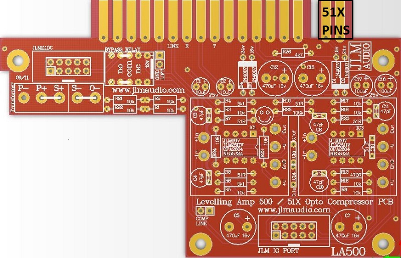
LA500A opto comp leveling amp BUILD THREAD 500/51X
Moderator: Joe Malone
-
Joe Malone

- Site Admin
- Posts: 2080
- Joined: Wed Jan 24, 2007 11:35 pm
- Location: Brisbane, Australia
- Contact:
Re: LA500A opto comp leveling amp BUILD THREAD 500/51X
Check the long leg of the led went to the rectangle pad.dneilsen wrote:Just finished my first LA500A kit and it sounds great.
I have noticed one small issue with my build though.
When I enable the slow attack mode the yellow LED does not light.
I do not have a massive understanding of electronics and was hoping someone can point me as to where I should start to look for the issue.
Thanks
If not sure email a close in focus photo of the led attached to the pot pcb with front panel removed so I can see inside it and let you know if it is in the correct way or not.
Joe 
JLM Audio
Capturing Audio without Injury
JLM Audio
Capturing Audio without Injury
Re: LA500A opto comp leveling amp BUILD THREAD 500/51X
Dammit.
Looks like i have put the LED Diode in the wrong way (Flat side is towards the square which is wrong).
Doh!
ok, ill swap it around.
For a guy that hasnt soldered anything more than cables for about 30 years I guess that one mistake in a build is not too bad
Just shows how easy these kits are to make though
You do not have the required permissions to view the files attached to this post.
Re: LA500A opto comp leveling amp BUILD THREAD 500/51X
Just confirming.
All fixed.
All fixed.
-
Joe Malone
- Site Admin
- Posts: 2080
- Joined: Wed Jan 24, 2007 11:35 pm
- Location: Brisbane, Australia
- Contact:
Re: LA500A opto comp leveling amp BUILD THREAD 500/51X
Cool great to hear it was that simple and that you found the kits easy to builddneilsen wrote:Dammit.
Looks like i have put the LED Diode in the wrong way (Flat side is towards the square which is wrong).
Doh!
ok, ill swap it around.
For a guy that hasnt soldered anything more than cables for about 30 years I guess that one mistake in a build is not too bad
Just shows how easy these kits are to make though
Just confirming.
All fixed.
Joe
JLM Audio
Capturing Audio without Injury
JLM Audio
Capturing Audio without Injury
Re: LA500A opto comp leveling amp BUILD THREAD 500/51X
Hey Joe,
Thanks for the awesome kit. I've just built, but am running into an issue during calibration that I'm hoping you help me out with.
I'm only getting about .5vac on the output when I measure between pins 2 and 3. Even if I crank my signal generator in Protools, I can't get the output up to 1.23vac.
I took the module apart and reflowed my solder points, but the issue persists.
Any insights into troubleshooting this?
Thanks!!
Phil
-
Joe Malone
- Site Admin
- Posts: 2080
- Joined: Wed Jan 24, 2007 11:35 pm
- Location: Brisbane, Australia
- Contact:
Re: LA500A opto comp leveling amp BUILD THREAD 500/51X
OK with the comp VU/OFF/GR switched to off the hard bypass relay is on so can you now get 1.23vac on the output XLR?plevine wrote:Hey Joe,
Thanks for the awesome kit. I've just built, but am running into an issue during calibration that I'm hoping you help me out with.
I'm only getting about .5vac on the output when I measure between pins 2 and 3. Even if I crank my signal generator in Protools, I can't get the output up to 1.23vac.
I took the module apart and reflowed my solder points, but the issue persists.
Any insights into troubleshooting this?
Thanks!!
Phil
With the comp switched to VU can you get 1.23vac by turning up the makeup control?
What D/A are you using for the output tone signal?
Joe
JLM Audio
Capturing Audio without Injury
JLM Audio
Capturing Audio without Injury
Re: LA500A opto comp leveling amp BUILD THREAD 500/51X
Hi Joe,
Thanks for the quick response!
When the module is switched off, I get 1.2 vac on the output.
I'd like to confirm again when I get home (in several hours), but I believe I am able to hit 1.23vac (if not more) if I turn up the makeup gain on the module.
D/A is an Apollo Firewire, line output. Another detail worth mentioning is that I measured the line output of the Apollo at -18 dBFS with a 1k sine tone, and it was significantly lower than 1.23vac - closer to 0.9vac. I compensated for this difference by boosting level in the session until the Apollo output read 1.23vac.
-
Joe Malone
- Site Admin
- Posts: 2080
- Joined: Wed Jan 24, 2007 11:35 pm
- Location: Brisbane, Australia
- Contact:
Re: LA500A opto comp leveling amp BUILD THREAD 500/51X
OK there is something wrong in the build if you do not get unity gain with threshold & Makeup Gain fully CCW. Email me some photos of the built LA500A first and then maybe some tops and bottoms of both PCB's if you get stuck.plevine wrote:Hi Joe,
Thanks for the quick response!
When the module is switched off, I get 1.2 vac on the output.
I'd like to confirm again when I get home (in several hours), but I believe I am able to hit 1.23vac (if not more) if I turn up the makeup gain on the module.
D/A is an Apollo Firewire, line output. Another detail worth mentioning is that I measured the line output of the Apollo at -18 dBFS with a 1k sine tone, and it was significantly lower than 1.23vac - closer to 0.9vac. I compensated for this difference by boosting level in the session until the Apollo output read 1.23vac.
Joe
JLM Audio
Capturing Audio without Injury
JLM Audio
Capturing Audio without Injury
Re: LA500A opto comp leveling amp BUILD THREAD 500/51X
So...I just completed one of these kits (big feat for me, started soldering this year). Haven't fed power to it yet but I found out that the two rear contacts marked +24 and -24 on the PCB prevent me from fully inserting the unit into my 500 series Neve rack. Pictures to follow...
-
Joe Malone
- Site Admin
- Posts: 2080
- Joined: Wed Jan 24, 2007 11:35 pm
- Location: Brisbane, Australia
- Contact:
Re: LA500A opto comp leveling amp BUILD THREAD 500/51X
If the 51X +/-24v edge connector interfere is it just cut off with sidecutter flush against the main pcb. The original BIO PCB had long edge connector which always needed cutting off but the new BIO PCB has a short edge connector which will fit in all racks that have edge sockets with no bolts in the mounting holes.ruben759 wrote:So...I just completed one of these kits (big feat for me, started soldering this year). Haven't fed power to it yet but I found out that the two rear contacts marked +24 and -24 on the PCB prevent me from fully inserting the unit into my 500 series Neve rack. Pictures to follow...
Joe
JLM Audio
Capturing Audio without Injury
JLM Audio
Capturing Audio without Injury
Re: LA500A opto comp leveling amp BUILD THREAD 500/51X
I just received my LA500A kit and instead of a black relay labeled P-12, I got a white one labeled P-24.
Does anyone know if this a part substitution?
Does anyone know if this a part substitution?
-
Joe Malone
- Site Admin
- Posts: 2080
- Joined: Wed Jan 24, 2007 11:35 pm
- Location: Brisbane, Australia
- Contact:
Re: LA500A opto comp leveling amp BUILD THREAD 500/51X
Sorry for the stuff up. Seems to be a one off mistake hopefully as all the rest of that batch here have P-12. Sending correct part out today to you.ab2010 wrote:I just received my LA500A kit and instead of a black relay labeled P-12, I got a white one labeled P-24.
Does anyone know if this a part substitution?
P-24 relays which are 24v can be used in LA500A kits but the 1k8 on the sidechain PCB has to be changed to 680R.
Once that resistor is changed it works the same as P-12 with 1k8 resistor.
Joe
JLM Audio
Capturing Audio without Injury
JLM Audio
Capturing Audio without Injury
Re: LA500A opto comp leveling amp BUILD THREAD 500/51X
Last Christmas I bought a matched set of LA500A (BIO500v2 PCB) KITs from Joe, I finally had the time to build them, last weekend...!
Some tips for future builders:
Do not "Cut off locate tabs with cut cutters" like the build guide says, but instead break them off with pliers, gives a much cleaner result.
After you've "Wind the back nut fully down on to the 3 switches." Turn the back-nut three whole turns back, to prevent the switches from touching the front panel. This will give a perfect alignment. Like this picture, from the guide (attachment)
When it's time to solder the meter tabs, build guide says: "If the tabs spring up use a small screwdriver to hold them down while soldering". Instead I've used (wooden) chopsticks.
When it's time to fit the LED's. "With LED held hard against the front panel grab both legs at the front edge of the PCB holes. Fold both legs at 90 degrees and trim folded part of leg to about 3 to 5mm long."
While still in the faceplate hole, I flipped the LED around so I could bend the legs straight up. Cut the legs and then flip around again. With bent legs facing down, place LED legs in the holes and solder.
Calibration went smoothly on both units, I didn't do stereo matching yet, just to see, this week, how well the matched set of OPTO's sets do without the stereo calibration.
Last tip, for the first post of this build thread, maybe an idea to use a PDF file instead of a "first post" build guide. Like these files:
For High-Res this link: https://drive.google.com/uc?export=down ... OxMUpmpExe
For small file size, this link: https://drive.google.com/uc?export=down ... QBqM7zd46K
Thank you Joe, for this great product in KIT form and clear build guide!
Will let you know how they sound.
You do not have the required permissions to view the files attached to this post.