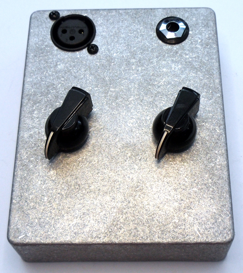
OLD Version Case
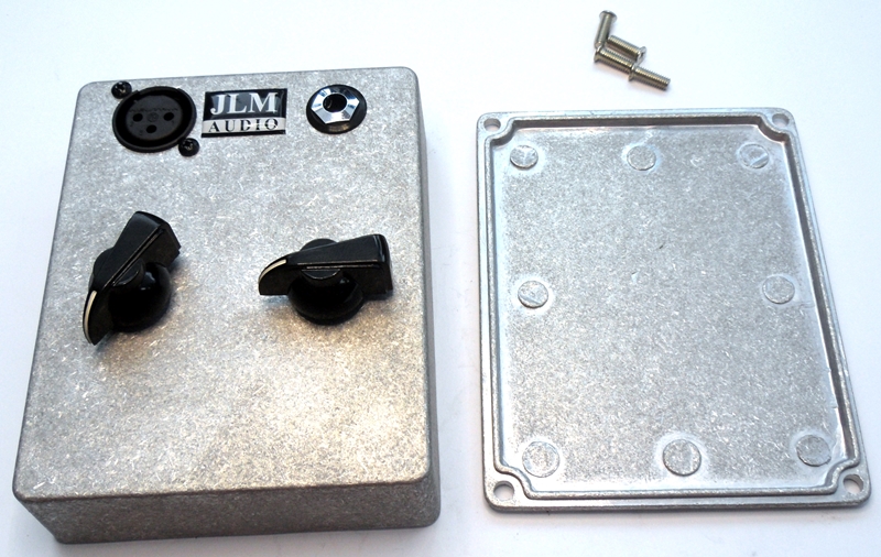
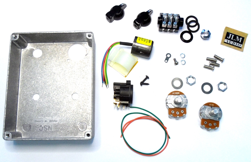
First unpack kit and check you have all the parts below. Plus box back panel not shown in photo.
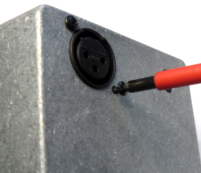
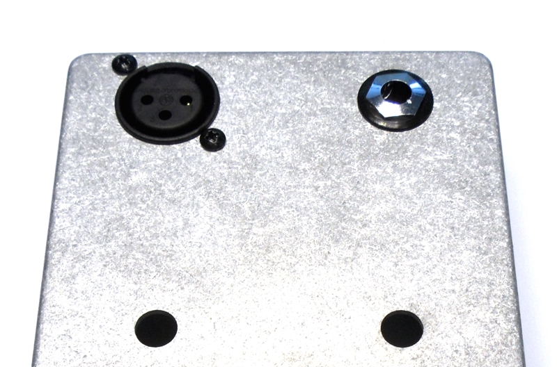
Start assembly by fitting the Female XLR inside the case.
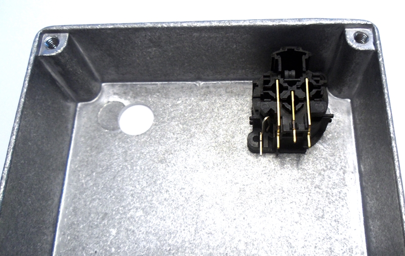
Use the 2 black self tapping screws to hold it into position.
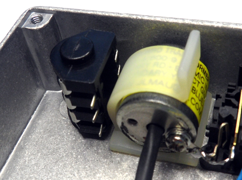
Fit JLM14 transformer into plastic clip
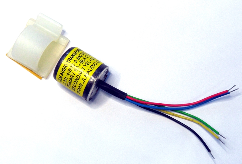
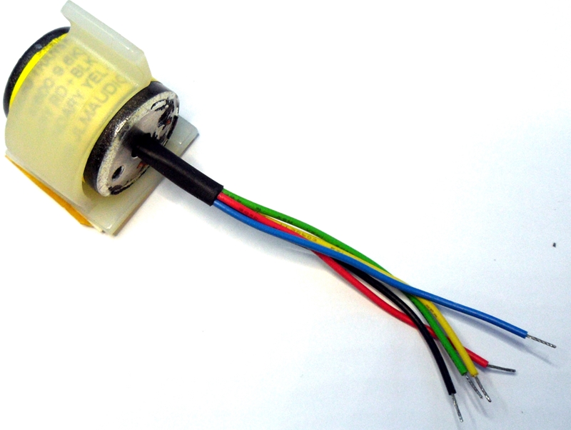
Remove protection plastic from double sided tape on clip
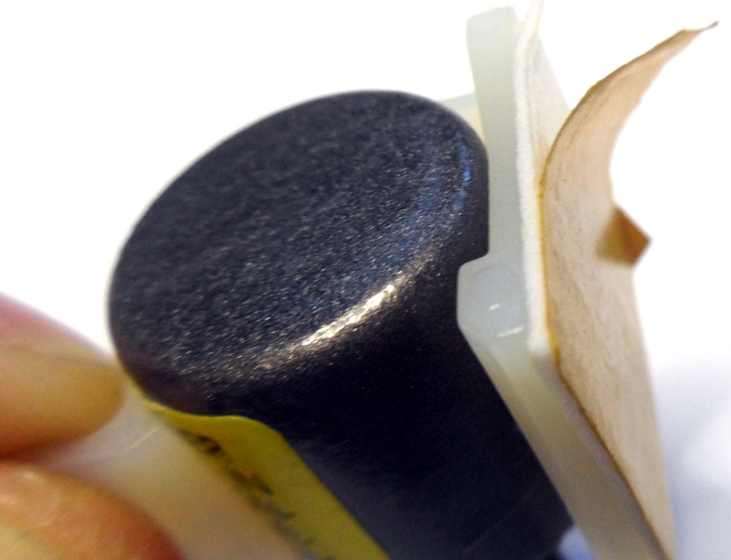
And stick to box hard against the top edge and as close to the XLR as possible

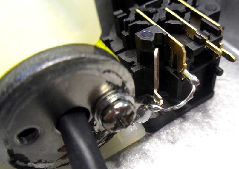
Screw ground lug to transformer with lock washer, ground lug, lock washer and 3M 6mm screw in that order.

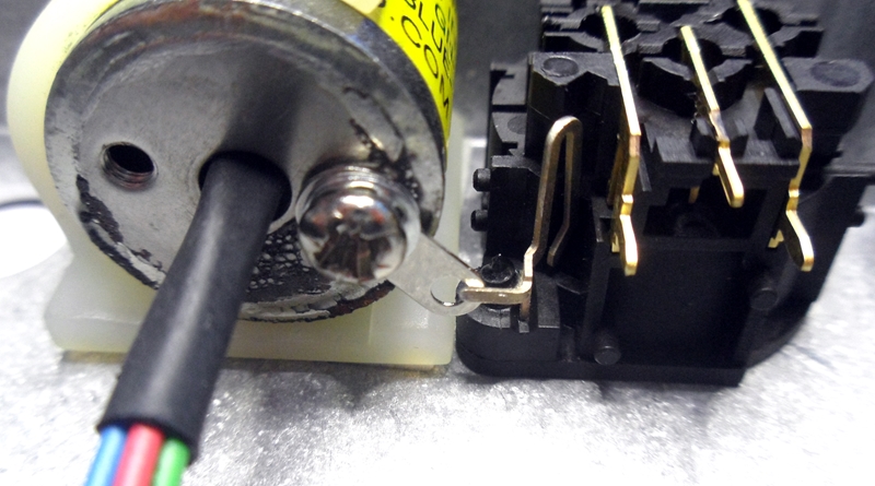
Fold ground tab on XLR 90 degrees and solder to transformer ground lug.

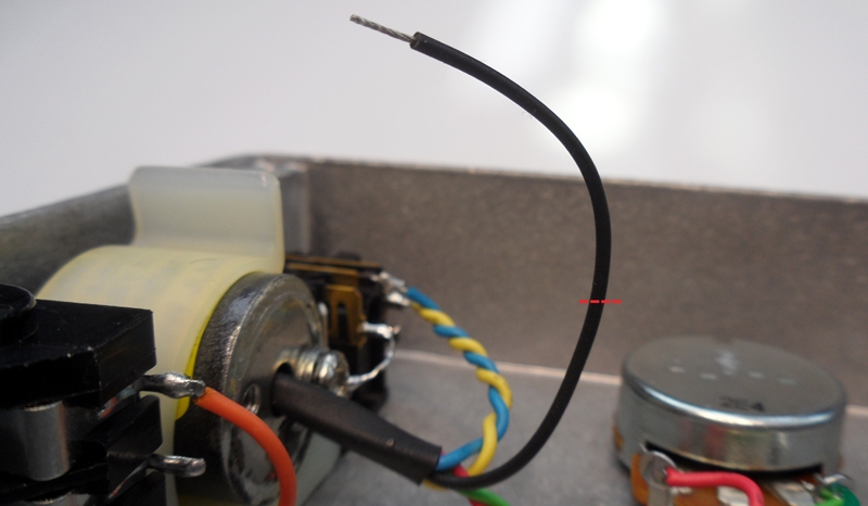
Pre solder XLR pin 1 and strip the end of the spare green wire and solder to XLR pin 1
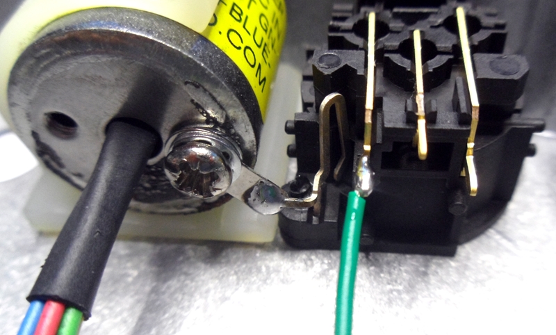
Cut green wire about 10mm away from solder and slide off green plastic.
Twist wires and solder to XLR ground tab.
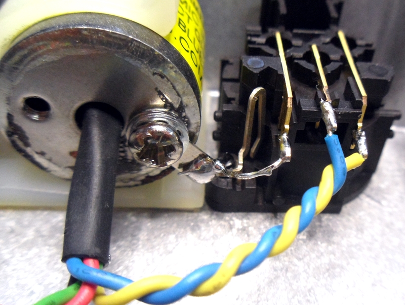
Pre solder XLR pin 2 and pin 3. Twist blue and yellow wires tightly and solder Blue wire to pin 3 and Yellow wire to pin 2.
Fold legs of TRS jack as shown below and fit the 2 fibre washers.
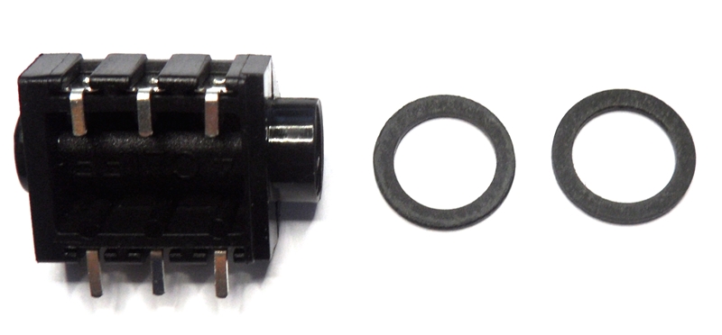
Fit into hole in case.
Use black dress ring and chrome nut to tighten to case.
Pre solder the 3 legs sticking out of the TRS Jack.
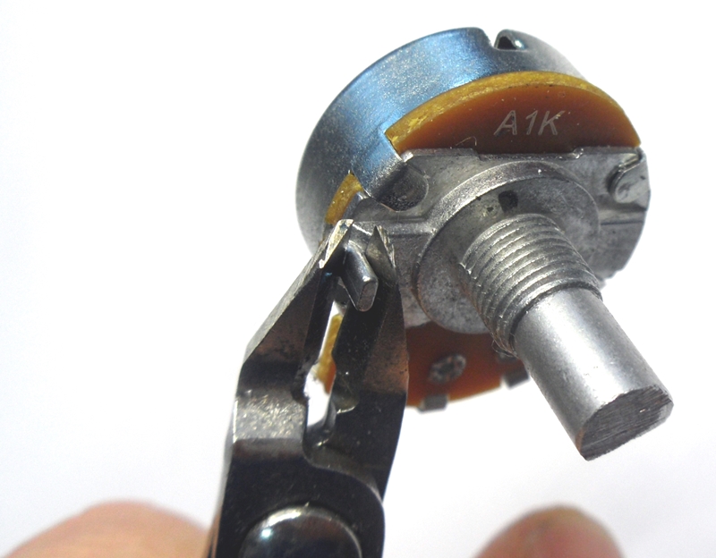
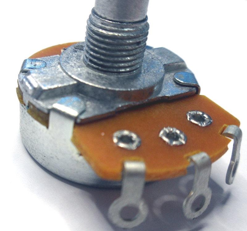
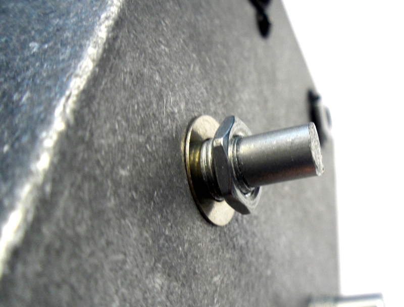
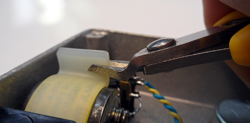
Cut pot locating tabs from the 1k and 100k pots.
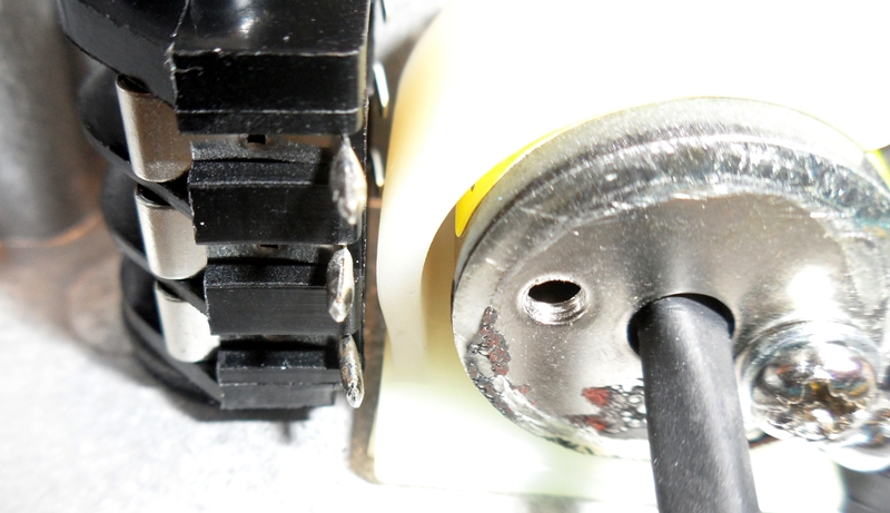
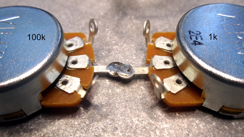
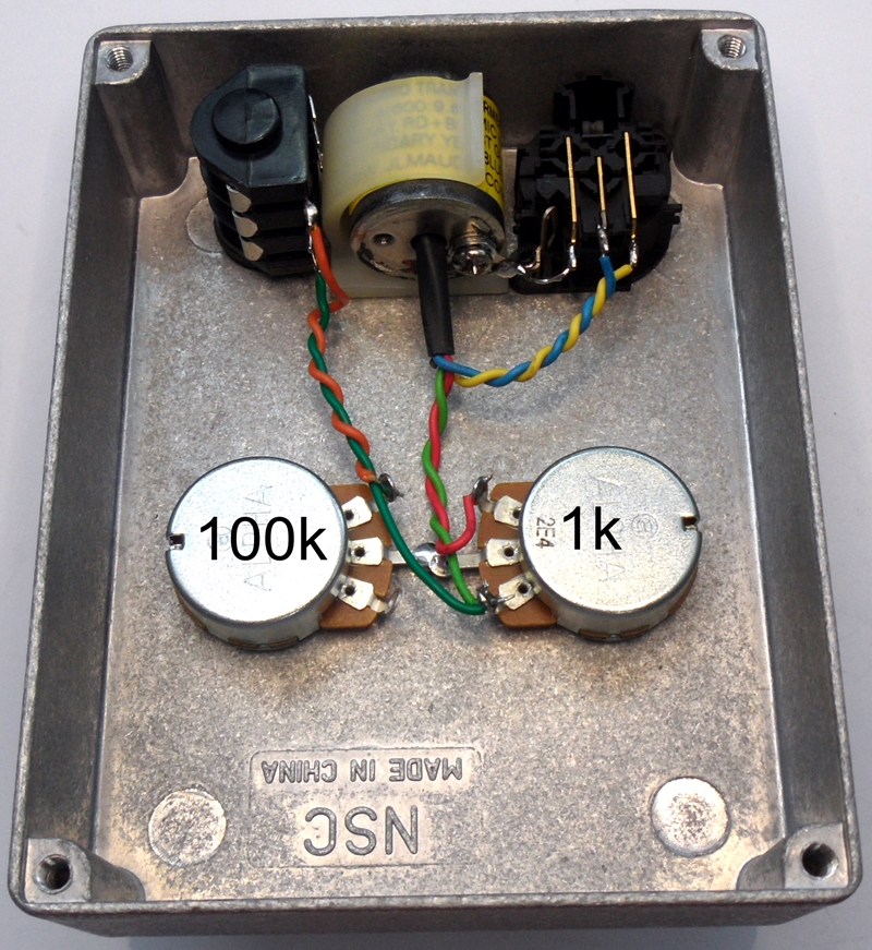
The 2 pots will go into the case as shown with 1k on left and 100k on right looking from on top.
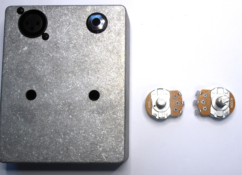
It is worth writing the pot values on there back covers as you will not be able to see these values once fitted in the box.

Fold centre wiper lug down as shown on both pots.
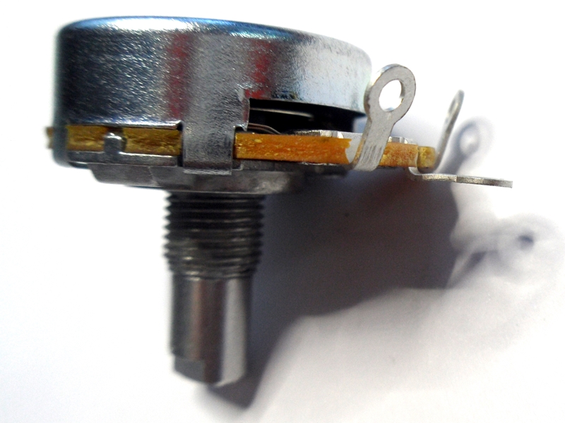
Fit both pots as below and by adding the washer and nut to each and tightening down.
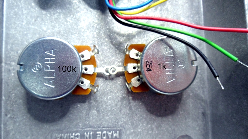
Solder pot centre wiper lugs together.
Tightly twist transformer Red and Green together and wrap tinned wire ends to 1k pot as shown.
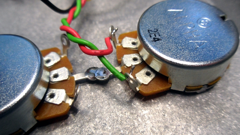
Solder Red wire to volume pot lug. and add second stripped and soldered green wire supplied into volume pot lug with transformer green wire.
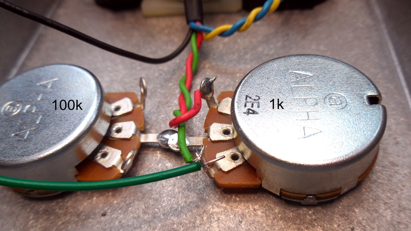
Solder both green wires in the volume pot lug.

Strip and solder end of orange wire supplied to impedance pot lug as shown.

Twist orange and green wires together.
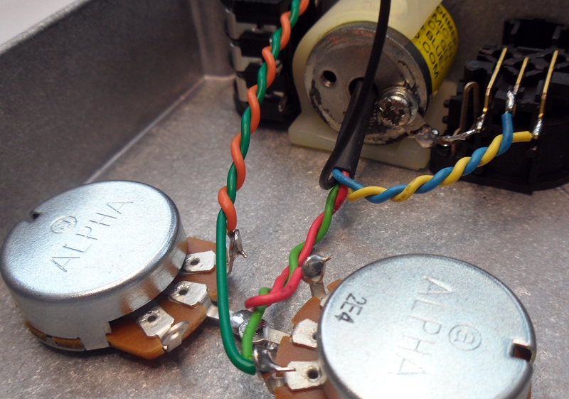
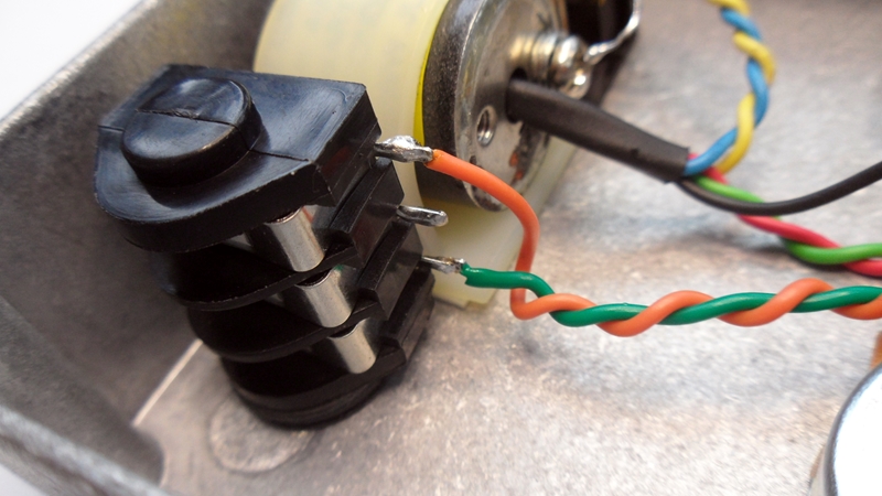
Cut twisted orange and green wire down in length so they reach the jack terminals with a bit to spare. Strip and solder both wire ends.
Solder green wire to bottom TRS jack terminal. And solder orange wire to top TRS jack terminal as shown.
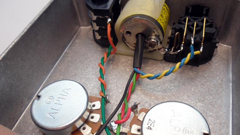
Cut black wire shorter and slide end back into the black heatshrink tube so it will not short to anything.
Cut transformers plastic clip down so the diecast lid just presses on it when fitted.
Double check your wiring and trim any sharp points on the end of any soldered wires.
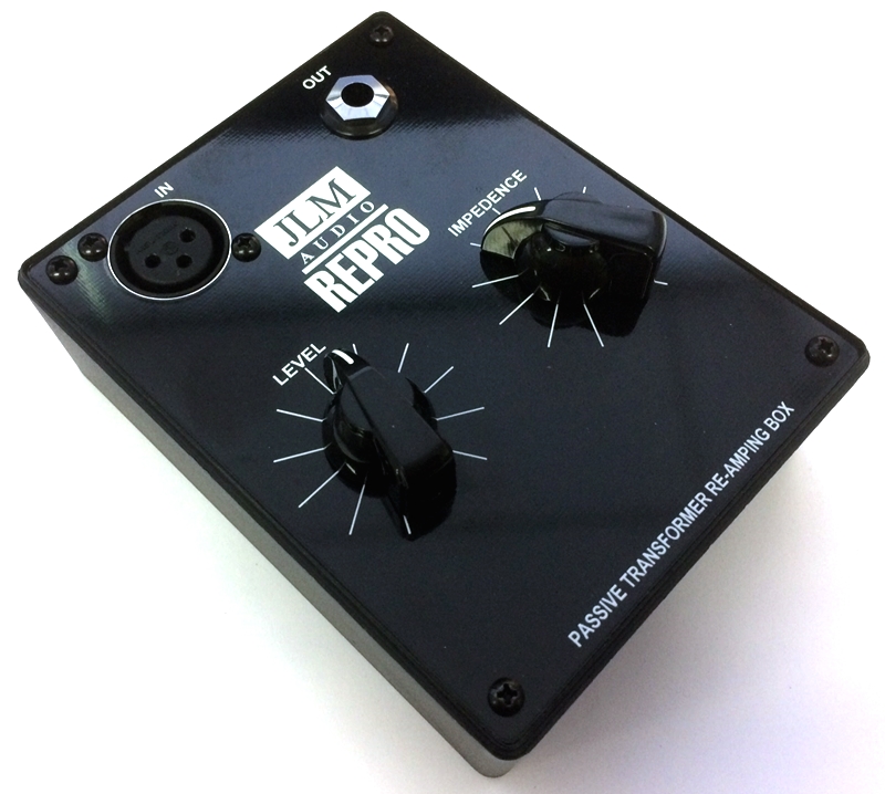
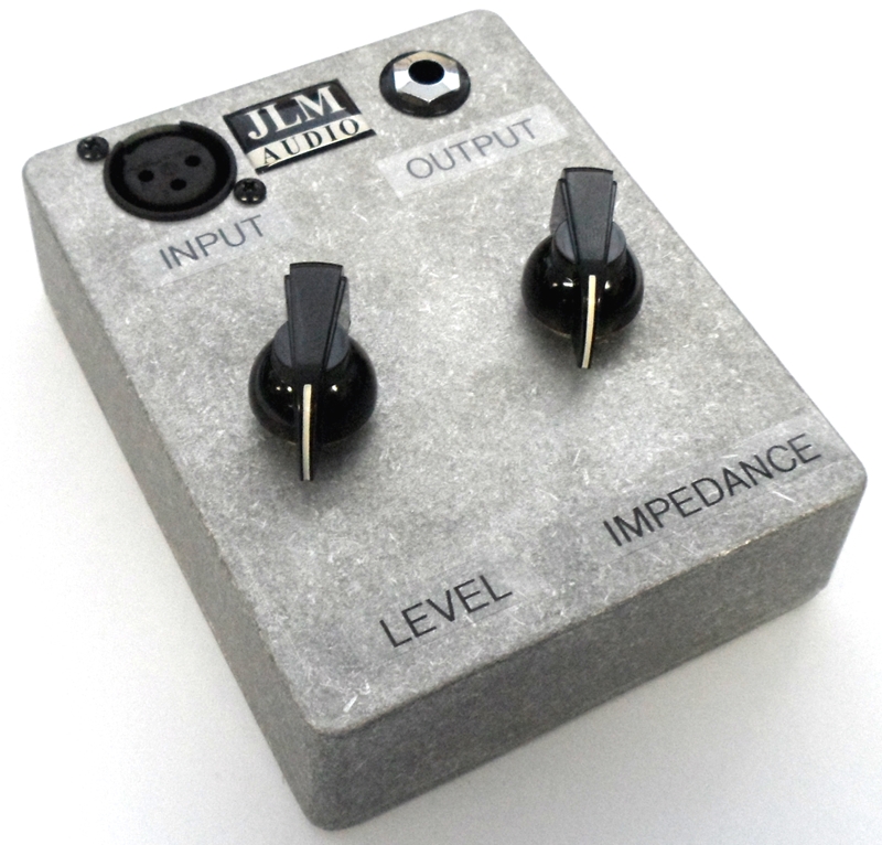
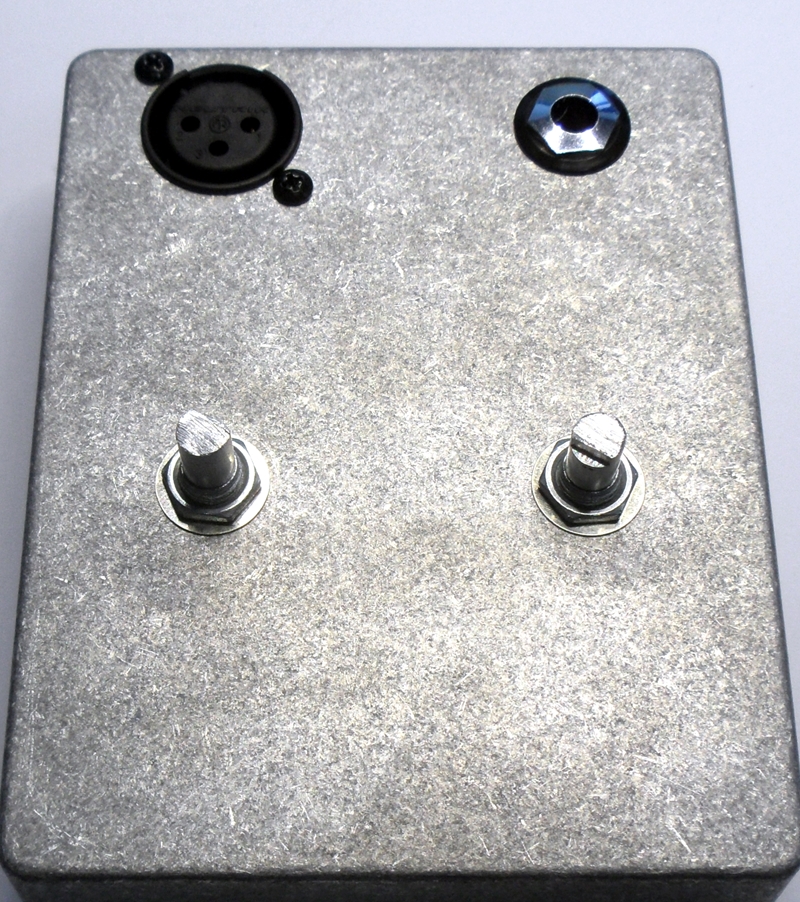
The reamp box can now be tested. In and out and controls are as shown below. Setting level and impedance pots to half there travel is a ideal starting point.
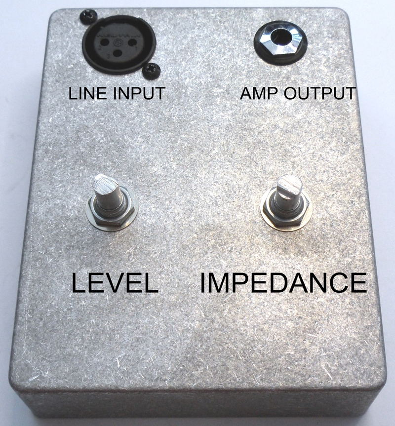
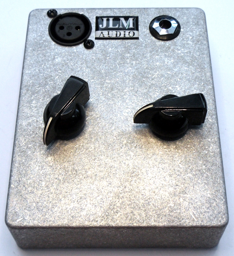
If the box works and you are not going to paint it now it is time to fit the knobs, logo, labeling & back of box.
Labeling can be done with dymo/brother labeling or by hand with permanent pen.
You could use any of the terms listed LINE INPUT = INPUT = IN. AMP OUTPUT = OUTPUT = OUT. VOLUME = LEVEL. IMPEDANCE = Z. etc