Passive Controller Build Thread Ver 1 - 3

Support for JLM Audio Kits

Moderator: Joe Malone

User avatar
Joe Malone
Site Admin
Posts: 2062
Joined: Wed Jan 24, 2007 11:35 pm
Location: Brisbane, Australia
Contact:

Passive Controller Build Thread Ver 1 - 3

Post by Joe Malone »

PCB to make Rob Squires Passive Monitor Controller easily. PCB available here

Our TASCAM / IDC to XLR / TRS IN & OUT PCB & STEREO IO PCB can be used with this pcb as well.
TASCAM / IDC to XLR / TRS IN & OUT PCB here
STEREO IO PCB here

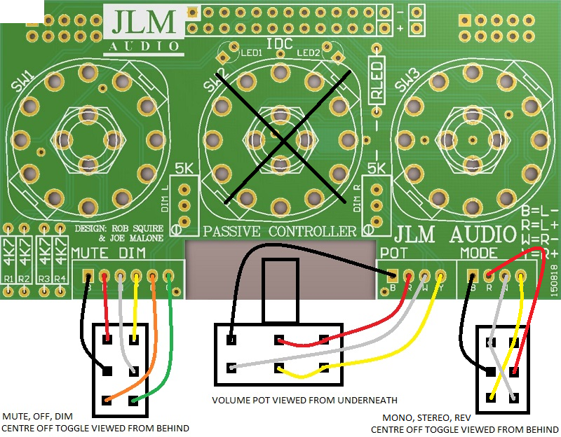
Passive Controller Wiring Ver 2 & 3
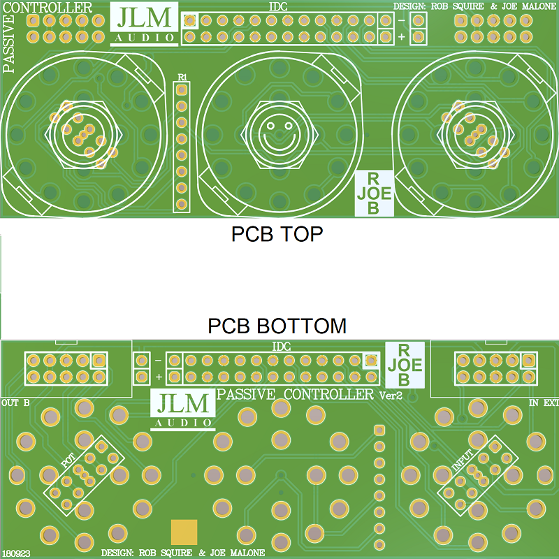
Passive Monitor Controller PCB ver 2 & 3 size is 86.9mm (3.42") x 36.9mm (1.34")
3 switches are spaced 30.48mm (1.2") appart centre to centre of the switch next to it.

See wiring diagram attachment at the bottom of this post.
Note 1. Square Pin 1 of 26 pin IDC cable header is pin 25 on DB25 connector.
Note 2. On this PCB mode control layout is MONO, STEREO, REV.
Note 3. All 10 pin connectors on ver 2 & 3 pcb follow the JLM STBUS pinout.
Note 4. Do not push rotary switches fully down to the pcb as they will short on pot and input solder joints under them.

STBUS = Pin 1 L+, pin 2 L-, pin 3&4 +V, pin 5&6 0v, pin 7&8 -V, pin 9 R-, pin 10 R+.
R1 is SIL of 4 x 4k7 or 4 x 4k7 1/4 resistors standing side by side.

Image

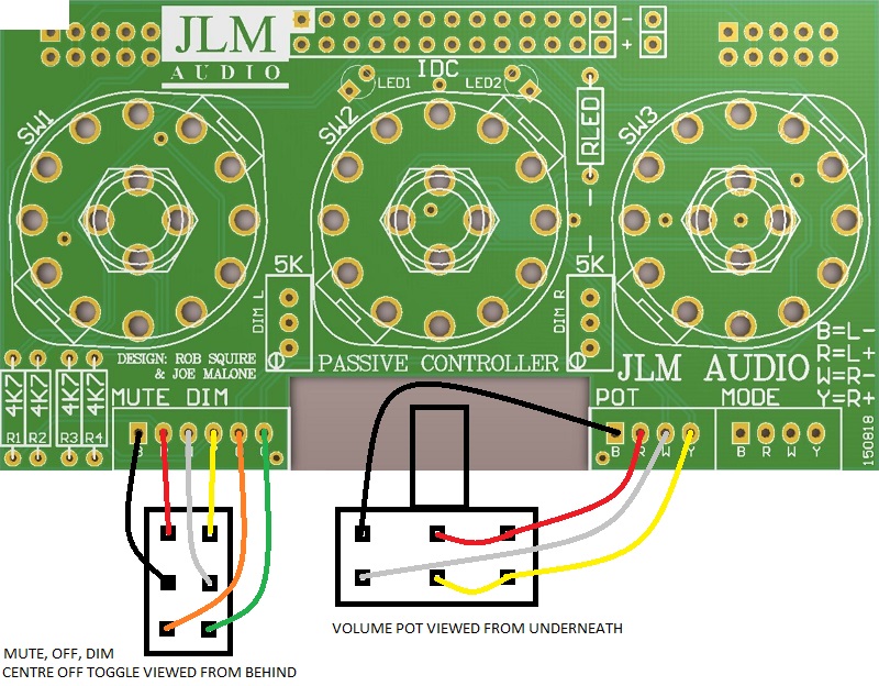
Passive Controller Wiring Ver 1
3 switches are spaced 30.48mm (1.2") appart centre to centre of the switch next to it.
Note 1. Square Pin 1 of 26 pin IDC cable header is pin 25 on DB25 connector.
note 2. On this PCB mode control layout is MONO, STEREO, REV.
Image

Link to Rob Squires original article on making the passive controller below.
http://www.jlmaudio.com/Reviews/AT78_OTB.pdf
You do not have the required permissions to view the files attached to this post.
Joe :-)
JLM Audio
Capturing Audio without Injury

Rocinante
Posts: 15
Joined: Fri Aug 26, 2016 3:02 am

Re: Passive Controller Build Thread

Post by Rocinante »

I've got these great illuminated push button EAO switches I'd like to use for my mute and dim switches. The switches have four pins (not including the led power pins) and are dpst. Can I wire them like I've drawn in the pic below?
Thanks again Joe!
Dylan
Imagescreenshot windows 7

User avatar
Joe Malone
Site Admin
Posts: 2062
Joined: Wed Jan 24, 2007 11:35 pm
Location: Brisbane, Australia
Contact:

Re: Passive Controller Build Thread

Post by Joe Malone »

Rocinante wrote:I've got these great illuminated push button EAO switches I'd like to use for my mute and dim switches. The switches have four pins (not including the led power pins) and are dpst. Can I wire them like I've drawn in the pic below?
Thanks again Joe!
Dylan
Imagescreenshot windows 7
If the contacts link top to bottom then yes should work perfectly.

but not sure how you will make the led turn on and off :-)
Joe :-)
JLM Audio
Capturing Audio without Injury

Rocinante
Posts: 15
Joined: Fri Aug 26, 2016 3:02 am

Re: Passive Controller Build Thread

Post by Rocinante »

Okay a few more questions.
The farthest left switch is the 'source' or 'input' switch. Is it an A - B switch or is there a mute in between?
What is 'mode" on the bottom right? Another mode switch?
And finally the pot is probably 10k dual gang rev log?
Cheers
And thank you.

Rocinante
Posts: 15
Joined: Fri Aug 26, 2016 3:02 am

Re: Passive Controller Build Thread

Post by Rocinante »

Joe Malone wrote:
If the contacts link top to bottom then yes should work perfectly.

but not sure how you will make the led turn on and off :-)
Yes the contacts are supposed to link top to bottom of each side. I believe when the button is engaged it turns the led on but I haven't used them yet. They are also rated at 42v (such a weird rating) which I will be using my extra phantom power rail (I am using the five fish triple rail psu 2448) to power them. Here's a pic

Imagecapture screen

User avatar
Joe Malone
Site Admin
Posts: 2062
Joined: Wed Jan 24, 2007 11:35 pm
Location: Brisbane, Australia
Contact:

Re: Passive Controller Build Thread

Post by Joe Malone »

Rocinante wrote:Okay a few more questions.
The farthest left switch is the 'source' or 'input' switch. Is it an A - B switch or is there a mute in between?
What is 'mode" on the bottom right? Another mode switch?
And finally the pot is probably 10k dual gang rev log?
Cheers
And thank you.
Left switch in input 1, mute, 2
Right switch is output 1, mute, 2
The ten pin header above each switch is wired to the mute position for a 3rd in or out using our Stereo IO PCB and 10 wire ribbon cable.

If the centre rotary mode switch mono, stereo , rev is not fitted the mode connector can allow these functions to be done with external switches instead.
Joe :-)
JLM Audio
Capturing Audio without Injury

User avatar
Joe Malone
Site Admin
Posts: 2062
Joined: Wed Jan 24, 2007 11:35 pm
Location: Brisbane, Australia
Contact:

Re: Passive Controller Build Thread

Post by Joe Malone »

Rocinante wrote:
Joe Malone wrote:
If the contacts link top to bottom then yes should work perfectly.

but not sure how you will make the led turn on and off :-)
Yes the contacts are supposed to link top to bottom of each side. I believe when the button is engaged it turns the led on but I haven't used them yet. They are also rated at 42v (such a weird rating) which I will be using my extra phantom power rail (I am using the five fish triple rail psu 2448) to power them. Here's a pic

Imagecapture screen
The separate lamp terminals at each end go directly to the lamp.

Best to check the current draw of the lamps before trying to run them off a pump charged 48v phantom rail
Joe :-)
JLM Audio
Capturing Audio without Injury

Rocinante
Posts: 15
Joined: Fri Aug 26, 2016 3:02 am

Re: Passive Controller Build Thread

Post by Rocinante »

Thanks a bunch Joe for the replies. I had read this article and built their project years ago. To see it on a pcb is awesome especially that you made it so modifiable.
Cheers

User avatar
Joe Malone
Site Admin
Posts: 2062
Joined: Wed Jan 24, 2007 11:35 pm
Location: Brisbane, Australia
Contact:

Re: Passive Controller Build Thread

Post by Joe Malone »

Rocinante wrote:Thanks a bunch Joe for the replies. I had read this article and built their project years ago. To see it on a pcb is awesome especially that you made it so modifiable.
Cheers
Yes Rob & I talked lots to work out how to make the PCB as flexible as possible :-)
Joe :-)
JLM Audio
Capturing Audio without Injury

Rocinante
Posts: 15
Joined: Fri Aug 26, 2016 3:02 am

Re: Passive Controller Build Thread

Post by Rocinante »

Joe Malone wrote: If the centre rotary mode switch mono, stereo , rev is not fitted the mode connector can allow these functions to be done with external switches instead.
Care to elaborate (via a diagram if possible :wink: )but I'd definitely suffice with an explanation. I'm leaning in this external switch direction and have been banging my head trying to rewire it to make it work with some bad ass illuminated pushbutton switches i picked up. They range from spst to 3pdt. This is being used in a fully balanced line mixer i am building but if all goes well i will use it in the monitor controller im building as an add on too. The mixer uses neve 1272 replicas for summing and has a bunch of features. If i could get a master section half as awesome as your mastering mixer it would be the bees knees.
Thanks in advance. I seriously appreciate it.
Dylan

User avatar
Joe Malone
Site Admin
Posts: 2062
Joined: Wed Jan 24, 2007 11:35 pm
Location: Brisbane, Australia
Contact:

Re: Passive Controller Build Thread

Post by Joe Malone »

You can wire an external mode switch or switches by leaving out the centre rotary switch and wiring to the mode connector as shown below.

Can be done with external rotary switch or centre off toggle or 2 dpst switches.

Image
Joe :-)
JLM Audio
Capturing Audio without Injury

Rocinante
Posts: 15
Joined: Fri Aug 26, 2016 3:02 am

Re: Passive Controller Build Thread

Post by Rocinante »

A thousand Thank you's Joe.

Rocinante
Posts: 15
Joined: Fri Aug 26, 2016 3:02 am

Re: Passive Controller Build Thread

Post by Rocinante »

And for clarity purposes I would wire it like below?


Imageimage ru

User avatar
Joe Malone
Site Admin
Posts: 2062
Joined: Wed Jan 24, 2007 11:35 pm
Location: Brisbane, Australia
Contact:

Re: Passive Controller Build Thread

Post by Joe Malone »

Rocinante wrote:And for clarity purposes I would wire it like below?


Imageimage ru
Yes correct if switching contacts vertical. Mono switch on the left and reverse right switch on the right
Joe :-)
JLM Audio
Capturing Audio without Injury

Rocinante
Posts: 15
Joined: Fri Aug 26, 2016 3:02 am

Re: Passive Controller Build Thread

Post by Rocinante »

Thank you thank you thank you. You just made my life sooooo much easier.


Cheers
Dylan

Post Reply