Hi
This is my first post here but I have been watching it for few years and have built 6 channels of BA´s.
I built a 2ch. pre. with --JLM14--Hybrid--Variable Z--Output trim-- and a 4ch. pre. with --OEP--OPA2604-- and I just love them and they get used all the time in my studio.
Now I planning my next build and I´m thinking about building a 2ch. BAD with transformers in and out, and discrete opamps.
So here is my question, I can get my hands on a pair of Carnhill VTB9045´s and was wondering if I could use them in BAD and what the load, or Zobel, resistor would be?
And could I still use the variable Z with them?
p.s. The Carnhill would be wired in 1:4 (300:4k8) to give ca.12db of gain.
Thanks in advanced,
Kristjan
BA BA2 BA4 BAD Dual99v Build Thread
Moderator: Joe Malone
-
Joe Malone

- Site Admin
- Posts: 2078
- Joined: Wed Jan 24, 2007 11:35 pm
- Location: Brisbane, Australia
- Contact:
Re: BA BA2 BA4 BAD Dual99v Build Thread
HI Kristjan Great to hear you are liking your BA presTrubbert wrote:Hi
This is my first post here but I have been watching it for few years and have built 6 channels of BA´s.
I built a 2ch. pre. with --JLM14--Hybrid--Variable Z--Output trim-- and a 4ch. pre. with --OEP--OPA2604-- and I just love them and they get used all the time in my studio.
Now I planning my next build and I´m thinking about building a 2ch. BAD with transformers in and out, and discrete opamps.
So here is my question, I can get my hands on a pair of Carnhill VTB9045´s and was wondering if I could use them in BAD and what the load, or Zobel, resistor would be?
And could I still use the variable Z with them?
p.s. The Carnhill would be wired in 1:4 (300:4k8) to give ca.12db of gain.
Thanks in advanced,
Kristjan
Since none of the Carnhills we have tested here have not performed like the original St Ives Neve transformers we have here it is hard to say what real Rload CLoad and RZobel CZobel parts would be for them.
But I am sure since it is 1:4 and Neve 10468 runs 180pF Cload with 6k Rload it would be best to use the standard JLM14 Rload variable 50k + 2k2 CLoad 220pF and no RZobel no CZobel parts.
Joe 
JLM Audio
Capturing Audio without Injury
JLM Audio
Capturing Audio without Injury
Re: BA BA2 BA4 BAD Dual99v Build Thread
Hi guys
Just a few short questions
I just got started on a BA2. I first emailed Joe and asked what to order for an API'ish style build. He said the JLM25HV and JLM14 wired 1:8. I suppose that's my first question, the notes say ratios higher than 1:6.45 not recommended. Should I just wire it 1:4 as it says in the table? Is that the safest course?
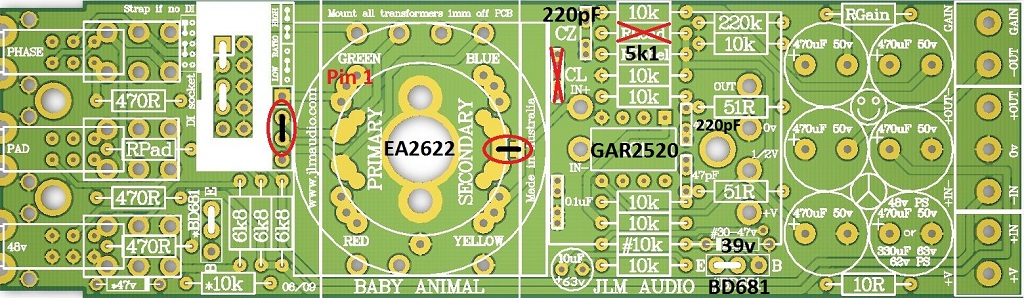
220pF cap (pictured top centre) which holes do you fit them in? the diagram has me worried.
In the diagram, the 39v, BD681; I don’t understand this stuff. I am using the JLM25HV, so I don’t connect the BD681. Do I just use wire to short circuit those two holes as shown? Is that it? Does that achieve the 39v that it indicates?
Resistor sections on the PCB that say *10k and #10k, how do these differ from the other 10k spots? (more a general interest question)
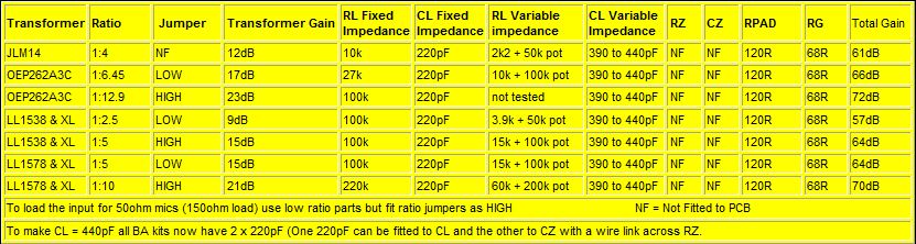
using JLM14 and JLM25HV (taken from diagram and yellow table under the JLM14 (1:4 row)
RZobel: 5k1 (need to buy separately? Didn’t come in the kit)
RGain: 68R
RPad: 120R
RLoad: not fitted
CL: not fitted
CZ: 220 pF
Is that all correct?
Dave
Just a few short questions
I just got started on a BA2. I first emailed Joe and asked what to order for an API'ish style build. He said the JLM25HV and JLM14 wired 1:8. I suppose that's my first question, the notes say ratios higher than 1:6.45 not recommended. Should I just wire it 1:4 as it says in the table? Is that the safest course?
220pF cap (pictured top centre) which holes do you fit them in? the diagram has me worried.
In the diagram, the 39v, BD681; I don’t understand this stuff. I am using the JLM25HV, so I don’t connect the BD681. Do I just use wire to short circuit those two holes as shown? Is that it? Does that achieve the 39v that it indicates?
Resistor sections on the PCB that say *10k and #10k, how do these differ from the other 10k spots? (more a general interest question)
using JLM14 and JLM25HV (taken from diagram and yellow table under the JLM14 (1:4 row)
RZobel: 5k1 (need to buy separately? Didn’t come in the kit)
RGain: 68R
RPad: 120R
RLoad: not fitted
CL: not fitted
CZ: 220 pF
Is that all correct?
Thanks very much for your time and helpJoe Malone wrote:
BA Settings (Ratios higher than 1:6.45 below not recommended unless using 50ohm microphones)
Building API 512, API 312 type mic pre on BA PCB
If using JLM25HV or JLM25HV FET NO BD681 is needed & 33v - 39v zener as they can run direct on the +/-24v of the BA PCB.
Dave
-
Joe Malone
- Site Admin
- Posts: 2078
- Joined: Wed Jan 24, 2007 11:35 pm
- Location: Brisbane, Australia
- Contact:
Re: BA BA2 BA4 BAD Dual99v Build Thread
HI DaveDavidL wrote:Hi guys
Just a few short questions
I just got started on a BA2. I first emailed Joe and asked what to order for an API'ish style build. He said the JLM25HV and JLM14 wired 1:8. I suppose that's my first question, the notes say ratios higher than 1:6.45 not recommended. Should I just wire it 1:4 as it says in the table? Is that the safest course?
220pF cap (pictured top centre) which holes do you fit them in? the diagram has me worried.
In the diagram, the 39v, BD681; I don’t understand this stuff. I am using the JLM25HV, so I don’t connect the BD681. Do I just use wire to short circuit those two holes as shown? Is that it? Does that achieve the 39v that it indicates?
Resistor sections on the PCB that say *10k and #10k, how do these differ from the other 10k spots? (more a general interest question)
using JLM14 and JLM25HV (taken from diagram and yellow table under the JLM14 (1:4 row)
RZobel: 5k1 (need to buy separately? Didn’t come in the kit)
RGain: 68R
RPad: 120R
RLoad: not fitted
CL: not fitted
CZ: 220 pF
Is that all correct?
Thanks very much for your time and helpJoe Malone wrote:
BA Settings (Ratios higher than 1:6.45 below not recommended unless using 50ohm microphones)
Building API 512, API 312 type mic pre on BA PCB
If using JLM25HV or JLM25HV FET NO BD681 is needed & 33v - 39v zener as they can run direct on the +/-24v of the BA PCB.
Dave
JLM14 used as 1:8 use black wire instead of green wire. All other wires stay the same. So place black wire where it says green. And tape up the green wire so it doesn't short to anything.
RZobel: 5k1 (need to buy separately? Didn’t come in the kit) 10k works fine
RGain: 68R
RPad: 120R
RLoad: not fitted
CL: not fitted
CZ: 220 pF fit in CZ positon. Caps have different spaced leads so each side of cz position as 2 pads connected.
Link out both BD681 positions C to E and *10k #10k are also not needed but fine to leave on the PCB when using JLM25HV as it runs on the full 48v (+/-24v)
Joe
JLM Audio
Capturing Audio without Injury
JLM Audio
Capturing Audio without Injury
Re: BA BA2 BA4 BAD Dual99v Build Thread
Hey again
slowly working through the build with my limited spare time. Just a few more quick questions
If I’m connecting the DI sections, do I still need to jumper the 4 slots as shown in the diagram? If so what is the best way to do that?
The three slots that I've circled in the diagram. Are these all connected together? The reason i ask is I somehow managed to snap the 10k resistor clean out of the socket, with the snipped wires still sticking out and I can't for the life of my get one of them out. If the three connectors are indeed connected, since the RLoad is to be left unfitted, I would be able to maybe put the 10k resistor as shown in the second diagram attached
You do not have the required permissions to view the files attached to this post.
-
Joe Malone
- Site Admin
- Posts: 2078
- Joined: Wed Jan 24, 2007 11:35 pm
- Location: Brisbane, Australia
- Contact:
Re: BA BA2 BA4 BAD Dual99v Build Thread
You have to remove the 2 jumpers when plugging in the DI kit. So the Di has control over switching between MIC and DI input.DavidL wrote:Hey again
slowly working through the build with my limited spare time. Just a few more quick questions
If I’m connecting the DI sections, do I still need to jumper the 4 slots as shown in the diagram? If so what is the best way to do that?
No. The 2 holes to the left are connected. But the one to the right is connected to 0v. The wire link you have drawn doesn't make any sense to me.The three slots that I've circled in the diagram. Are these all connected together? The reason i ask is I somehow managed to snap the 10k resistor clean out of the socket, with the snipped wires still sticking out and I can't for the life of my get one of them out. If the three connectors are indeed connected, since the RLoad is to be left unfitted, I would be able to maybe put the 10k resistor as shown in the second diagram attached
Joe
JLM Audio
Capturing Audio without Injury
JLM Audio
Capturing Audio without Injury
Re: BA BA2 BA4 BAD Dual99v Build Thread
Hi Joe and everyone I hope you're all in excellent health and mood.
I've posted a few photos on my Facebook about latest recording session i did for a brass band. Tagged JLM Audio FB page as well: https://www.facebook.com/djani.pervan
The recording went smoothly most of the time but on the third day I started losing the signal from BA2 preamp second channel where the room mic was plugged in.
The connection would easy reestablish after I switch off and back on the preamp (that was the quickest workaround I could find)
So now I'm back home and got some time to fix the unit I wanna ask you if you got any hints why this is happening. Same thing happens no matter if its condenser phantom power powered or dynamic or ribbon mic plugged into that channel. The signal after undetermined amount of time simply disappears like if the physical contact is lost.
The unit was completely re-cabeled internally and power supply and second channel DI were changed almost year ago when I was building the 1290 units.
So please when you find the time drop me an email with some guidance of possible suspects.
Thank a lots! Cheers!
-
Joe Malone
- Site Admin
- Posts: 2078
- Joined: Wed Jan 24, 2007 11:35 pm
- Location: Brisbane, Australia
- Contact:
Re: BA BA2 BA4 BAD Dual99v Build Thread
HI DjaniHwidow wrote:Hi Joe and everyone I hope you're all in excellent health and mood.
I've posted a few photos on my Facebook about latest recording session i did for a brass band. Tagged JLM Audio FB page as well: https://www.facebook.com/djani.pervan
The recording went smoothly most of the time but on the third day I started losing the signal from BA2 preamp second channel where the room mic was plugged in.
The connection would easy reestablish after I switch off and back on the preamp (that was the quickest workaround I could find)
So now I'm back home and got some time to fix the unit I wanna ask you if you got any hints why this is happening. Same thing happens no matter if its condenser phantom power powered or dynamic or ribbon mic plugged into that channel. The signal after undetermined amount of time simply disappears like if the physical contact is lost.
The unit was completely re-cabeled internally and power supply and second channel DI were changed almost year ago when I was building the 1290 units.
So please when you find the time drop me an email with some guidance of possible suspects.
Thank a lots! Cheers!
No idea on this problem. Have you swapped opamps between channels to see if the fault follow the opamp?
Joe
JLM Audio
Capturing Audio without Injury
JLM Audio
Capturing Audio without Injury
Re: BA BA2 BA4 BAD Dual99v Build Thread
Hi Joe. I ordered a couple of BA pcbs from you and im stuffing them right now. There is a 10 Uf cap i dont see in the schematic. What is it for?
And another question, the 470 uf cap that goes into the 6k8 48V resistors (the one sitting right over the 470 uf/ 330 uf 63v one),,,,could i change this one to 220 uf? Im asking because i have an overpopulation of 220 uf caps over here..and if it is to tame down the 48 thump im assuming i could use a 220 uf here....Thanks a mill! Your boards rock!
And another question, the 470 uf cap that goes into the 6k8 48V resistors (the one sitting right over the 470 uf/ 330 uf 63v one),,,,could i change this one to 220 uf? Im asking because i have an overpopulation of 220 uf caps over here..and if it is to tame down the 48 thump im assuming i could use a 220 uf here....Thanks a mill! Your boards rock!
Re: BA BA2 BA4 BAD Dual99v Build Thread
Hi, I've recently bought a BA4 with JLM14 input transformers, 2 x 99v and 2 x OPA. I've been reading this thread and the 50+ pages at group DIY and have a few questions:
- would it be possible to select 1:4/1:8 ratio on the transformer by mounting a switch that selects either the green or the black wire (without hum, noise and other unwanted issues)? I understand it would roll off low end earlier, so could be a useful "emulation" of a steel-core type (like the APIs) IMHO.
- should I fit a fuse – it's only shown in an BAD build, not straight BA – and should I measure current draw and select next larger value, or take the PSU rating and select next smaller value?
- would a DIY JE-990C require a change of capacitor like the 2520, and if so, to which value?
- could I install one pair of output transformers and make the selectable for either channels 1&2 or 3&4 with a switch, or would the extra wiring wreck havoc?
BTW I'm a little surprised that the JLM2520 seems to get so little love – what's not to like about a +/-24V 2520 ?
Thanks to JLM for the kit and the support!
-
Joe Malone
- Site Admin
- Posts: 2078
- Joined: Wed Jan 24, 2007 11:35 pm
- Location: Brisbane, Australia
- Contact:
Re: BA BA2 BA4 BAD Dual99v Build Thread
The 10uF is extra power rail smoothing only.Ayguid wrote:Hi Joe. I ordered a couple of BA pcbs from you and im stuffing them right now. There is a 10 Uf cap i dont see in the schematic. What is it for?
And another question, the 470 uf cap that goes into the 6k8 48V resistors (the one sitting right over the 470 uf/ 330 uf 63v one),,,,could i change this one to 220 uf? Im asking because i have an overpopulation of 220 uf caps over here..and if it is to tame down the 48 thump im assuming i could use a 220 uf here....Thanks a mill! Your boards rock!
You could basically use 220uF caps for all instead of 470uF without a problem. It only means the difference between roughly a 2Hz to 4Hz roll off point.
Joe
JLM Audio
Capturing Audio without Injury
JLM Audio
Capturing Audio without Injury
-
Joe Malone
- Site Admin
- Posts: 2078
- Joined: Wed Jan 24, 2007 11:35 pm
- Location: Brisbane, Australia
- Contact:
Re: BA BA2 BA4 BAD Dual99v Build Thread
If you keep the wiring short there should be no problem doing this at all.ask wrote:Hi, I've recently bought a BA4 with JLM14 input transformers, 2 x 99v and 2 x OPA. I've been reading this thread and the 50+ pages at group DIY and have a few questions:
- would it be possible to select 1:4/1:8 ratio on the transformer by mounting a switch that selects either the green or the black wire (without hum, noise and other unwanted issues)? I understand it would roll off low end earlier, so could be a useful "emulation" of a steel-core type (like the APIs) IMHO.
The 10R on each PCB is technically the fuse for each PCB but we always run a fuse on the back panel and yes best to make it a small as possible without blowing on power up surge. So low value and slow blow is often the way to go.- should I fit a fuse – it's only shown in an BAD build, not straight BA – and should I measure current draw and select next larger value, or take the PSU rating and select next smaller value?
If it oscillates then you may need to but I think it will be fine with standard value.- would a DIY JE-990C require a change of capacitor like the 2520, and if so, to which value?
No this is also fine and will have no noise problems but the thing to watch out for is to keep this wiring away from the low level input wiring.- could I install one pair of output transformers and make the selectable for either channels 1&2 or 3&4 with a switch, or would the extra wiring wreck havoc?
We have sold 100s of them so somebody likes themBTW I'm a little surprised that the JLM2520 seems to get so little love – what's not to like about a +/-24V 2520 ?
Thanks to JLM for the kit and the support!
Joe
JLM Audio
Capturing Audio without Injury
JLM Audio
Capturing Audio without Injury
Re: BA BA2 BA4 BAD Dual99v Build Thread
Hi Joe!. I was wondering if i could use the 48V rail of your PSU ACDC,, to run just 2 BA using 5532. Thanks!
-
Joe Malone
- Site Admin
- Posts: 2078
- Joined: Wed Jan 24, 2007 11:35 pm
- Location: Brisbane, Australia
- Contact:
Re: BA BA2 BA4 BAD Dual99v Build Thread
Yes that will work fine as long as the 48v reg is heatsinked to a metal case or good heatsink.Ayguid wrote:Hi Joe!. I was wondering if i could use the 48V rail of your PSU ACDC,, to run just 2 BA using 5532. Thanks!
Joe
JLM Audio
Capturing Audio without Injury
JLM Audio
Capturing Audio without Injury
Re: BA BA2 BA4 BAD Dual99v Build Thread
Joe Malone wrote: Have you swapped opamps between channels to see if the fault follow the opamp?
Thanks Joe! Have tried swapping opamps and noticed immediately that 99V on second channel have been slightly loose and out from its golden socket legs.
It is likely due to transport of the equipment rack every single night for two weeks for those brass band sessions.
I'm afraid to squeeze these golden sockets to get better grip, maybe its better if I try to tighten it up over "belly" a bit with sort of a belt or something.
Tested for more than hour recording and not a single glitch. Thanks again for the tip! Cheers!