Hi,...
Maybe i need to make 2 or 4 mono amps, but first i like to "see" how sound looks.
Do you have the same pcb to a sub-woofer amp?
Thanks, Luis
JLM 60Watt Power AMP Kit
Moderator: Joe Malone
-
Joe Malone

- Site Admin
- Posts: 2081
- Joined: Wed Jan 24, 2007 11:35 pm
- Location: Brisbane, Australia
- Contact:
Re: JLM 60Watt Power AMP Kit
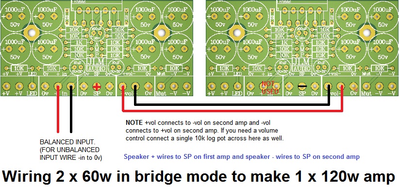
A pair of AMP kits can make a 140w amp for a sub but I do not have a sub filter PCB which should have a 12 to 24dB filter slope.slb1959 wrote:Hi,...
Maybe i need to make 2 or 4 mono amps, but first i like to "see" how sound looks.
Do you have the same pcb to a sub-woofer amp?
Thanks, Luis
Joe 
JLM Audio
Capturing Audio without Injury
JLM Audio
Capturing Audio without Injury
Re: JLM 60Watt Power AMP Kit
Hi,
I'm building a single killatone as per http://www.johnlsayers.com/phpBB2/viewt ... f=12&t=297 but with a fostex 120. But I think that is largely irrelevant to my question which is about the baffle step compensation. Instead of the passive design shown, I am thinking of using Rod Elliots line level design http://sound.westhost.com/bafflestep.htm.(8 inch baffle results in about a 20nF (edit - 18 nF) cap)
What is the best way to incorporate this design into the amp?
I would like to retain the volume pot so I can match the level with my main monitors, so does that mean the series resister and cap as discussed earlier in this thread is out of contention? If so do I need to unbalance the input (or just use one side?) and put Rod's circuit between my soundcard and the amp input? Any caveats attached to doing that?
Many thanks
Mike
Last edited by mike_s on Sun May 13, 2012 6:27 am, edited 1 time in total.
-
Joe Malone
- Site Admin
- Posts: 2081
- Joined: Wed Jan 24, 2007 11:35 pm
- Location: Brisbane, Australia
- Contact:
Re: JLM 60Watt Power AMP Kit
OK first off the killatone has the driver offset on the box front to minimize the step response of the baffle.mike_s wrote:Hi,
I'm building a single killatone as per http://www.johnlsayers.com/phpBB2/viewt ... f=12&t=297 but with a fostex 120. But I think that is largely irrelevant to my question which is about the baffle step compensation. Instead of the passive design shown, I am thinking of using Rod Elliots line level design http://sound.westhost.com/bafflestep.htm.(8 inch baffle results in about a 20nF cap)
What is the best way to incorporate this design into the amp?
If you let me know the f3 you want and max step amount like 6dB etc and if you are wanting to use balanced or unbalanced input? I can show you how to make it work with the volume control option still.I would like to retain the volume pot so I can match the level with my main monitors, so does that mean the series resister and cap as discussed earlier in this thread is out of contention? If so do I need to unbalance the input (or just use one side?) and put Rod's circuit between my soundcard and the amp input? Any caveats attached to doing that?
Joe
JLM Audio
Capturing Audio without Injury
JLM Audio
Capturing Audio without Injury
Re: JLM 60Watt Power AMP Kit
Hi Joe, thanks for helping.
As I understand it from Rod's page (and others) f3 is simply a function of the baffle size, so 380/0.66 = 570 Hz.
I have a small L-shaped room, and it will go kind of in the bend if that makes any sense, about 2-3 feet on each side to the nearest wall and about 3 feet out from the back. I don't know if that counts as free space or an enormous bass resonator, which is why I was looking at Rod's design with the variable gain (I do have a reasonable amount of bass trapping). So I guess it would be worth having the whole 6dB available?
re. Balancing - I use Rob Squire's DIY monitor switching design, and it is balanced all the way, so if I had an option I'd stay balanced. But I'm not hung up about it.
thx
Mike
Re: JLM 60Watt Power AMP Kit
How to wire + , - and G from PSU to amp ( Bridge AMP )?flaheu wrote:
Cheers
and I'd like to connect LED too. Please, Help..
Thx
Minguta.
-
Joe Malone
- Site Admin
- Posts: 2081
- Joined: Wed Jan 24, 2007 11:35 pm
- Location: Brisbane, Australia
- Contact:
Re: JLM 60Watt Power AMP Kit
Wire the power supply + to both AMP PCB +V and same for - and G (0v). You can star or daisy chain wire either will work fine.Minguta wrote:How to wire + , - and G from PSU to amp ( Bridge AMP )?flaheu wrote:
Cheers
and I'd like to connect LED too. Please, Help..
Thx
Minguta.
The LED anode (long leg) wires to the LED terminal on either AMP PCB and the cathode (short leg) wires to 0v on any AMP PCB. The series resistor for the LED is already on the AMP PCB.
Joe
JLM Audio
Capturing Audio without Injury
JLM Audio
Capturing Audio without Injury
-
fonzobrown
- Posts: 2
- Joined: Mon May 27, 2013 5:53 am
Re: JLM 60Watt Power AMP Kit
Hi Joe, i've buyed one of this pcb and two amb head....do You provide schematics for both projects?
Thanks
Roberto
Thanks
Roberto
-
Joe Malone
- Site Admin
- Posts: 2081
- Joined: Wed Jan 24, 2007 11:35 pm
- Location: Brisbane, Australia
- Contact:
Re: JLM 60Watt Power AMP Kit
Yes if you send us a email request for them we do. We do not put them up on the forum as to many companies have just cloned our designs in the past.fonzobrown wrote:Hi Joe, i've buyed one of this pcb and two amb head....do You provide schematics for both projects?
Thanks
Roberto
Building using the PCB overlay the device will work as designed.
Are you having problems with the build or are you wanting to customize it for your special needs? If so always best to explain to us what problem you are having or what you are trying to make so we can help you first by email.
I cannot find a email from you in our system at this moment.
Joe
JLM Audio
Capturing Audio without Injury
JLM Audio
Capturing Audio without Injury
-
fonzobrown
- Posts: 2
- Joined: Mon May 27, 2013 5:53 am
Re: JLM 60Watt Power AMP Kit
Oh yes, Joe, i've just email'ed almost 10 days ago ...but maybe your anti spam is too aggressive or just my mistake cause i've replied to your order confirmation email : (
However of course i understand your point on cloning things...but my intent it's just customization/learning so i'm just do it a new request by private message @ your sales email account
Sorry if i've soiled this thread a bit ( it's ok if you wanna delete my post for making this thread an easy reading )
Thanks
Roberto
-
Joe Malone
- Site Admin
- Posts: 2081
- Joined: Wed Jan 24, 2007 11:35 pm
- Location: Brisbane, Australia
- Contact:
Re: JLM 60Watt Power AMP Kit
Got your new email and sent reply with info and attachmentfonzobrown wrote:Oh yes, Joe, i've just email'ed almost 10 days ago ...but maybe your anti spam is too aggressive or just my mistake cause i've replied to your order confirmation email : (
However of course i understand your point on cloning things...but my intent it's just customization/learning so i'm just do it a new request by private message @ your sales email account
Sorry if i've soiled this thread a bit ( it's ok if you wanna delete my post for making this thread an easy reading )
Thanks
Roberto
Joe
JLM Audio
Capturing Audio without Injury
JLM Audio
Capturing Audio without Injury
Re: JLM 60Watt Power AMP Kit
Hi
I just finished building my second Power AMP (the first one is working for a couple of years now, all well), and I have a problem with huge DC offset (-25VDC) on one channel.
The other channel is working fine.
There are no shorts, no wrong parts, no wrong orientation (checked several times, compared to working ch.).The signal flow is identical on both channels.
DC is present only on the pins 1&5= +27VDC, pin 4= -27VDC, unwanted -25VDC @ pin 3 and -3.5VDC on pin 8 on the channel with the huge DC offset.
All other pins are DC free.
If I disconnect wire link from -(27)VDC to the mute pad, DC offset from the output is gone. 100uF 35V cap from the mute pin is oriented the right way and there are no shorts
from -VDC, mute parts or any other parts to the output,( apart from feedback resistors one end).
LM3886 with no heatsink and no input signal, gets just mildly warm, no smoke, just this huge dc offset.
Help please !!!
-
Joe Malone
- Site Admin
- Posts: 2081
- Joined: Wed Jan 24, 2007 11:35 pm
- Location: Brisbane, Australia
- Contact:
Re: JLM 60Watt Power AMP Kit
I would need to see photos to check over the PCB soldering for shorts etc but if mute off removes dc then the DC is coming from the pin 9 & 10 inputs of the LM3886. Do you see any dc voltage at pin 9 & pin 10?syn wrote:Hi
I just finished building my second Power AMP (the first one is working for a couple of years now, all well), and I have a problem with huge DC offset (-25VDC) on one channel.
The other channel is working fine.
There are no shorts, no wrong parts, no wrong orientation (checked several times, compared to working ch.).The signal flow is identical on both channels.
DC is present only on the pins 1&5= +27VDC, pin 4= -27VDC, unwanted -25VDC @ pin 3 and -3.5VDC on pin 8 on the channel with the huge DC offset.
All other pins are DC free.
If I disconnect wire link from -(27)VDC to the mute pad, DC offset from the output is gone. 100uF 35V cap from the mute pin is oriented the right way and there are no shorts
from -VDC, mute parts or any other parts to the output,( apart from feedback resistors one end).
LM3886 with no heatsink and no input signal, gets just mildly warm, no smoke, just this huge dc offset.
Help please !!!
Also you can never run a LM3886 without a heatsink as the internal 50mA bias at +/-27v is enough heat to make the LM3886 go into protection but that shouldn't make DC on the output.
Joe
JLM Audio
Capturing Audio without Injury
JLM Audio
Capturing Audio without Injury
Re: JLM 60Watt Power AMP Kit
Hi Joe
Thank you very much. Photos would not do much good, as most of the parts I used are SMD on adapters soldered from both sides of the PCB. Anyhow, the problem solved, the whole trick was that DC offset appeared on the pin 3 only and nowhere else , not even on the FB resistor connected to the pin 3

 as I had a "cold" joint there so basically, my FB loop was broken! All fixed now, working great, sounds wonderful. Great design on your part, thank you very much.
Cheers
Thank you very much. Photos would not do much good, as most of the parts I used are SMD on adapters soldered from both sides of the PCB. Anyhow, the problem solved, the whole trick was that DC offset appeared on the pin 3 only and nowhere else , not even on the FB resistor connected to the pin 3
Cheers
-
Joe Malone
- Site Admin
- Posts: 2081
- Joined: Wed Jan 24, 2007 11:35 pm
- Location: Brisbane, Australia
- Contact:
Re: JLM 60Watt Power AMP Kit
Ok cool. Great to hear you got it workingsyn wrote:Hi Joe
Thank you very much. Photos would not do much good, as most of the parts I used are SMD on adapters soldered from both sides of the PCB. Anyhow, the problem solved, the whole trick was that DC offset appeared on the pin 3 only and nowhere else , not even on the FB resistor connected to the pin 3
Cheers
Joe
JLM Audio
Capturing Audio without Injury
JLM Audio
Capturing Audio without Injury