VUPPMGR40v3 kit (40 Led PPM/VU/GR Meter kit) BUILD THREAD
Moderator: Joe Malone
- Joe Malone
- Site Admin
- Posts: 2080
- Joined: Wed Jan 24, 2007 11:35 pm
- Location: Brisbane, Australia
- Contact:
VUPPMGR40v3 kit (40 Led PPM/VU/GR Meter kit) BUILD THREAD
Available now on JLM web shop here
40 Led Meter displays PPM and VU ballistics with peak hold at the same time. Also can be switched to show CV gain reduction.
•40 x 1dB steps
•Shows PPM in red with peak hold.
•Shows VU in Green with peak hold.
•Balanced/Unbalanced input with front level adjustment.
•PCB 106mm(4.2") x 50.4mm(2")
•PCBs can be stacked 15mm apart with hex threaded spacers.
•Can be powered from +/-12vdc to +/-24vdc (less than 50mA total current draw all leds lit).
•Can have on board tiny 24vdc to 5vdc SMPS or +5v can be supplied externally.
Software version 2.0
All features marked V2 are new features in latest version 2.0.
(The New 50Mhz PIC used for ver 2 software doesn't use the 20Mhz xtal or 2 x 15pF. So they can be fitted or not.)
20 pin IDC header which can daisy chained to other 40 led PPM/VU/GR PCBs
PIn 1,3,5,7,9,11,13,15 = 0v
Pin 2. Jumper1 for LED Brightness (Jumper GND Bright, 2.5v Dim, 5v Dimmer) V2.
Pin 4. Jumper2 for classic colour VU with PPM peak led V2.
Pin 6. Jumper3 for Classic colour mode 1 (K18 headroom) no jumper. Classic colour mode 2 (K14 headroom) jumper fitted V2
Pin 8. Jumper4 for direction change of meter right to left / Left to right V1 & V2
Pin 10. Jumper5 for turn off VU peak hold. V1 & V2
Pin 12. Jumper6 NOT USED V1 & V2
Pin 14. Jumper7 for Peak hold lock with reset when jumper shorted. If jumper left on then defaults to peak hold with decay drop back. V1 & V2
Pin 16. Jumper8 for switching to CV input. V1 & V2
Pin 17&18. +5v
Pin 19. -V
Pin20. +V
(All jumpers can be switched or changed on the fly)(Jumper 1 is closest to the VU balance trim pot)
e.g You can switch direction and to CV input to have a Gain reduction meter that travels in the reverse direction to the VUPPM meter.
SW jumper switched to 0v to switch to CV input for input on back terminals for Gain reduction.
Ver 2 software no long uses sync between meters. So Master/Slave jumper now used for CV voltage direction
Master/Slave jumper- CV change from 0>5 to 5>0
J6 open changes release time of PPM to roughly same as VU release time.
J6 closed changes release time of PPM to standard longer release time.
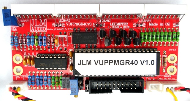
VUPPM Assembly
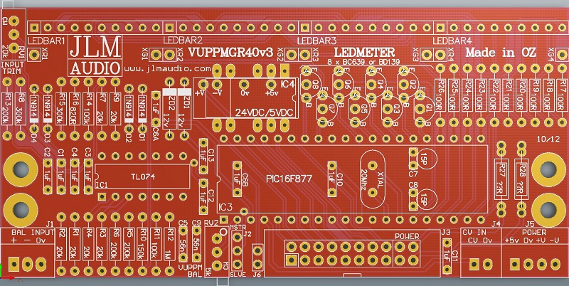
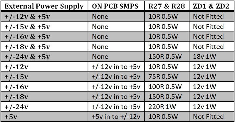
The VUPPM has all parts values on the PCB overlay and is a normal build from the lowest to tallest height component.
Only component changes that need to be done depending on power supply voltages are listed in the table below. So usually best to work out these parts and fit them first. Also a good idea to fit all resistor to the PCB beofre soldering them to make sure you do not put one in the wrong place. For those not good with colour codes bend the legs of the resistor ready for the PCB and place them into a ohmmeter terminals (without any test leads) to check the resistor value before placing in the PCB.
The 4 Tri colour 10 LED Bars need to have the 10 legs bent down 90degree which can be done with a flat metal ruler etc so they all bend in a straight line. Top 2 legs need to be bent 60degrees so they will reach into the XG & XR pads. Best to only solder one of the bottom legs on each display until you have the 4 bars fitted in a straight line.
The 8 x BD139 transistors all face with their plastic side facing the JLM AUDIO logo end of the PCB. So do pin 1 of the TL074 and PIC CPU IC.
Diodes black or white stripes should line up with the thicker white stripe on the PCB overlay. All 1N914/1N4148 diodes stripes should be furthermost away from the LED displays and Zener diodes stripes if fitted should be closest to the LED Displays.
Any questions feel free to post here preferably or email me.
NEW VUPPMGR40v3 PCB Changes
Ver3 PCB can use +/-12v to +5v SMPS module or +5v to +/-12v module so meter can run on 5v plug pack.
Ver 3 PCB does NOT need to change value of R13 & R14 ever.
Have a stereo compact box and scale coming as well as a 1unit rack case scale. Looking for input on what other scale levels or types people are interested in like mono, 0DFS etc
Stereo compact box will have a optional pre made stereo D/A card for spdif and toslink inputs.
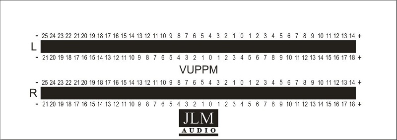
See scale examples below
Scale panel size 128mm (5.039") x 45mm (1.772") and fits Hammond Enclosure 1598B.
Rack version below
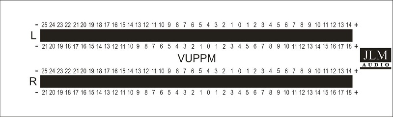
Scale panel size 128mm (5.039") x 38mm (1.496")
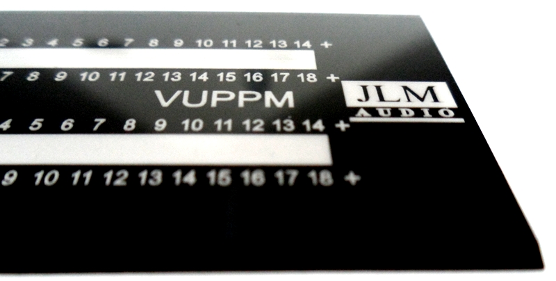
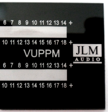
Photos of VUPPM Scale rack sample in 2mm clear perspex with black backing with laser cut text and bevelled edge.
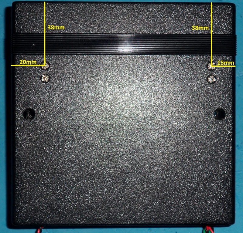
We use one of the PCBs against the front bezel with leds centred on the scale to drill the 4 holes in the bottom of the case.
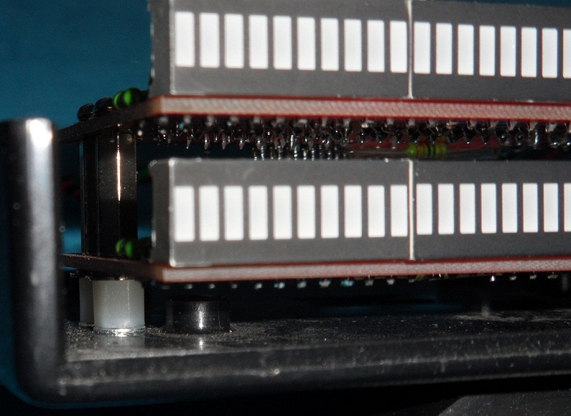
Then with 4 x 15mm to 20mm 3M bolts we position the bottom PCB with a 6mm plastic spacers with one lock washer below spacer and 2 lock washers above to make about a 7.5mm spacer.
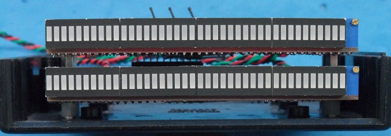
The 15mm bolts screw into the 15mm spacers. Then the second PCB is bolted with 6mm x 3M bolts to the 15mm spacers.
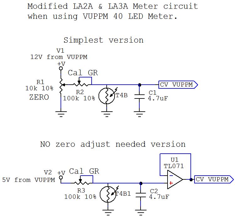
Using VUPPMGR40 instead of analog VU meter in GSSL, LA2A, LA3A circuits.
The VUPPMGR40 can have its balanced input connected direct across the output of the LA2A or LA3A clones for VUPPM output level.
Use the circuits below to interface the Gain Reduction T4B to the CV input on the VUPPMGR40. Set jumper on VUPPM PCB for 5v to 0v CV input.
A switch between SW terminal and 0v on the VUPPM PCB with switch between VUPPM output level and Gain reduction.
May also want to switch the meter to reverse direction on Gain reduction by switching that jumper as well.
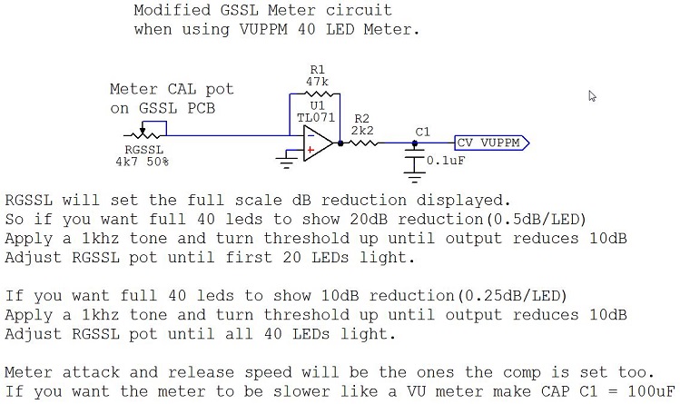
The VUPPMGR40 can have its balanced input connected direct across the output of the GSSL for VUPPM output level.
Use the circuits below to interface the GSSL Meter output to the CV input on the VUPPMGR40. Set jumper on VUPPM PCB for 0v to 5v CV input.
A switch between SW terminal and 0v on the VUPPM PCB with switch between VUPPM output level and Gain reduction.
May also want to switch the meter to reverse direction on Gain reduction by switching that jumper as well.
Joe
JLM Audio
Capturing Audio without Injury
JLM Audio
Capturing Audio without Injury
Re: VUPPMGR40v3 kit (40 Led PPM/VU/GR Meter kit) BUILD THREA
Hello Joe,
hope you're fine.
You said we should put our questions here,so here we go:
1:Will the jumper for LED brightness work on linked modules meaning is it possible to put a 3-position switch on the frontpanel for linked modules?
2:Could you please explain the peak LED Sync a bit more in-depth (does this refer to Hold or Decay times)?
3:If I understand it correct one can run the unit from just +5Vdc ("Wallwart").May I ask for the estimated current when all LEDs are lit?
4:Talking about the upcoming stereo compact box,will the D/A "eat" other formats than SPDIF too (e.g. AES/EBU)?
5:Will there be a link or loop-through for the digital input to do a chain (e.g main or master A/D interface ---Meter---digital input on next device) or must we provide an extra (stereo-) digtal out for it?
I know,many questions,but I'm the first to ask here it seems,mea culpa
Cheers,have a nice day,
Udo
- Joe Malone
- Site Admin
- Posts: 2080
- Joined: Wed Jan 24, 2007 11:35 pm
- Location: Brisbane, Australia
- Contact:
Re: VUPPMGR40v3 kit (40 Led PPM/VU/GR Meter kit) BUILD THREA
All meters connected by the same ribbon cable can share the one 3 position dim switch. 2.5v rail can be made with 2 x 1k resistors in series between the 0v and 5v rail. So a centre off toggle which short out either resistor will work.kante1603 wrote:Hello Joe,
hope you're fine.
You said we should put our questions here,so here we go:
1:Will the jumper for LED brightness work on linked modules meaning is it possible to put a 3-position switch on the frontpanel for linked modules?
All meters set to slave follow the meter set to master. It just sync the peak leds stepping back down together. Using the sync pin on the ribbon cable.2:Could you please explain the peak LED Sync a bit more in-depth (does this refer to Hold or Decay times)?
Yes 5v regulated or 5v SMPS wall wart like used for iphones and ipads etc. Total current per meter fully lit is about 100 to 150mA @ 5v on full brightness with the 5v to +/12v SMPS on the PCB.3:If I understand it correct one can run the unit from just +5Vdc ("Wallwart").May I ask for the estimated current when all LEDs are lit?
Yes at the moment we have spdif in and out and toslink in. USB in which also powers the whole box.4:Talking about the upcoming stereo compact box,will the D/A "eat" other formats than SPDIF too (e.g. AES/EBU)?
Only loop with spdif to spdif or toslink to spdif at the moment.5:Will there be a link or loop-through for the digital input to do a chain (e.g main or master A/D interface ---Meter---digital input on next device) or must we provide an extra (stereo-) digtal out for it?
Joe
JLM Audio
Capturing Audio without Injury
JLM Audio
Capturing Audio without Injury
Re: VUPPMGR40v3 kit (40 Led PPM/VU/GR Meter kit) BUILD THREA
Great,thank you for the infos Joe!
Best,
Udo.
Best,
Udo.
-
- Posts: 2
- Joined: Sat May 18, 2013 7:52 am
Re: VUPPMGR40v3 kit (40 Led PPM/VU/GR Meter kit) BUILD THREA
Hello Joe,
Is there any way this meter can be integrated into a type of DAW controller?? I would really like to use these meters for my next build, but I am not sure if these are capable of this.
- Joe Malone
- Site Admin
- Posts: 2080
- Joined: Wed Jan 24, 2007 11:35 pm
- Location: Brisbane, Australia
- Contact:
Re: VUPPMGR40v3 kit (40 Led PPM/VU/GR Meter kit) BUILD THREA
I am not sure exactly what you mean by DAW controller? But we have built them into heaps of devices. The VUPPM meter usually takes analog audio in like normal VU and PPM meters do.ibanman555 wrote:Hello Joe,
Is there any way this meter can be integrated into a type of DAW controller?? I would really like to use these meters for my next build, but I am not sure if these are capable of this.
But we have used several cheap small adaptors to run the meters on spdif, toslink, Aes-ebu and usb to audio converters to make the meters run on any digital signal we have needed to interface with.
So if you DAW controller has analog , spdif, toslink, AES-EBU and USB audio in it then yes. But you would need to let me know more so I could show you how to interface the VUPPM meters to your needs.
Joe
JLM Audio
Capturing Audio without Injury
JLM Audio
Capturing Audio without Injury
-
- Posts: 2
- Joined: Sat May 18, 2013 7:52 am
Re: VUPPMGR40v3 kit (40 Led PPM/VU/GR Meter kit) BUILD THREA
Joe,
Thanks for your quick response!
Basically, this would be a digital mixer that controls specific faders, knobs and buttons in programs such as ProTools, Logic, Ableton etc. These are only controlled thru MIDI messages and there isn't actual audio passing from controller to computer. I am probably stepping way out of the bounds of what is capable here, but I LOVE your meters and would love to integrate them somehow. Here is a link to the project at hand...
http://www.ucapps.de/midibox_lc.html
and/or
http://www.ucapps.de/midibox_ng.html (new version)
you can see some pdfs/schematics how the signal is programmed and the existing LED meters are hooked up.
There are options to connect CV outputs (http://www.midibox.org/dokuwiki/aout_ng), and I see your meters have CV inputs. This sparked my interest that there is a possibility to program the meter outputs of my audio workstation to your meters via CV... just a thought.
- Joe Malone
- Site Admin
- Posts: 2080
- Joined: Wed Jan 24, 2007 11:35 pm
- Location: Brisbane, Australia
- Contact:
Re: VUPPMGR40v3 kit (40 Led PPM/VU/GR Meter kit) BUILD THREA
THE CV is for using the meter to show compression in a audio compressor. You would need to send Stereo Audio or AES/EBU or SPDIF ro USB audio to make the meters work in your box.ibanman555 wrote:Joe,
Thanks for your quick response!
Basically, this would be a digital mixer that controls specific faders, knobs and buttons in programs such as ProTools, Logic, Ableton etc. These are only controlled thru MIDI messages and there isn't actual audio passing from controller to computer. I am probably stepping way out of the bounds of what is capable here, but I LOVE your meters and would love to integrate them somehow. Here is a link to the project at hand...
http://www.ucapps.de/midibox_lc.html
and/or
http://www.ucapps.de/midibox_ng.html (new version)
you can see some pdfs/schematics how the signal is programmed and the existing LED meters are hooked up.
There are options to connect CV outputs (http://www.midibox.org/dokuwiki/aout_ng), and I see your meters have CV inputs. This sparked my interest that there is a possibility to program the meter outputs of my audio workstation to your meters via CV... just a thought.
Joe
JLM Audio
Capturing Audio without Injury
JLM Audio
Capturing Audio without Injury
Re: VUPPMGR40v3 kit (40 Led PPM/VU/GR Meter kit) BUILD THREA
Hello,
Just finished assembling two 40 Led PPM/VU Meter kits into one Hammond case (1598BBK) with one of your VUPPM scale plate. It looks awesome and performs beautifully. I love of smooth the metering looks. Many thanks for putting this kit together!
I'm wondering how to best calibrate the kit (I'll be using the PPM and Vu meter mainly on the master out of my DAW when mixing projects).
What I did so far was fire up Logic and its Test Oscillator plugin, set to generate a 1KHz sine at 0dB with all the faders at 0dB. My understanding is that it a +4dBm signal (0dB vu) should then leave my sound interface.
Using the input trim (RV1) I set the red LEDs so that they just starts to light the last LED on the bank (+18 on the VUPPM scale), then using the balance trim (RV2) I set the green LEDs to just hit the "0" mark.
NB: I'm using the bottom of the scale (-21 dB to +18 dB).
Am I calibrating the PPM/VU meter correctly? I'm too sure about where to trim the peaks signal to.
Benjamin
- Joe Malone
- Site Admin
- Posts: 2080
- Joined: Wed Jan 24, 2007 11:35 pm
- Location: Brisbane, Australia
- Contact:
Re: VUPPMGR40v3 kit (40 Led PPM/VU/GR Meter kit) BUILD THREA
Cool please feel free to add any photos of your kit build to here or facebook or instagram with tag of jlmaudio for other to seebounav wrote:Hello,
Just finished assembling two 40 Led PPM/VU Meter kits into one Hammond case (1598BBK) with one of your VUPPM scale plate. It looks awesome and performs beautifully. I love of smooth the metering looks. Many thanks for putting this kit together!
TO Cal PPM to VU put in a 1kHz tone and turn up the input level trim RV1 pot until the 40th red led just turns on. Then turn up the VUPPM RV2 until the 40th green led just turns on. Now VU and PPM are calibrated to each other.I'm wondering how to best calibrate the kit (I'll be using the PPM and Vu meter mainly on the master out of my DAW when mixing projects).
What I did so far was fire up Logic and its Test Oscillator plugin, set to generate a 1KHz sine at 0dB with all the faders at 0dB. My understanding is that it a +4dBm signal (0dB vu) should then leave my sound interface.
Using the input trim (RV1) I set the red LEDs so that they just starts to light the last LED on the bank (+18 on the VUPPM scale), then using the balance trim (RV2) I set the green LEDs to just hit the "0" mark.
NB: I'm using the bottom of the scale (-21 dB to +18 dB).
Am I calibrating the PPM/VU meter correctly? I'm too sure about where to trim the peaks signal to.
The scale for the VUPPM has K14 & K18 scales on each side each meter. If you set 0VU = +4dBM on the K14 then the max 40th led will be +18dBM. If you set +4dBM on the K18 then max 40th led will be +22dBM.
Since it is a interface usually outputting a 1khz tone at full output without clipping and setting the input trim pot RV1 so the 40th led just lights will cal the VUPPM meter to your interface D/A out which usually clip somewhere between +18 to +22dBM.
Or if you are sure the interface outputs +4dBM with all faders flat then the way you have done the cal should be fine and can be checked by pushing the level up on the interface until it just about to clip and the 40th VUPPM led should just light.
Joe
JLM Audio
Capturing Audio without Injury
JLM Audio
Capturing Audio without Injury
Re: VUPPMGR40v3 kit (40 Led PPM/VU/GR Meter kit) BUILD THREA
Thanks for the calibration instructions Joe.
I wrote a short article about my stereo build of you kit on my blog: http://bounav.free.fr/wp/?p=361. The article contains a wiring diagram that details how to connect everything together. Hopefully some people will find it useful.Cool please feel free to add any photos of your kit build to here or facebook or instagram with tag of jlmaudio for other to see
Benjamin
- Joe Malone
- Site Admin
- Posts: 2080
- Joined: Wed Jan 24, 2007 11:35 pm
- Location: Brisbane, Australia
- Contact:
Re: VUPPMGR40v3 kit (40 Led PPM/VU/GR Meter kit) BUILD THREA
Wow Thanks Ben that is excellent I will point some more links towards the article.bounav wrote:Thanks for the calibration instructions Joe.
I wrote a short article about my stereo build of you kit on my blog: http://bounav.free.fr/wp/?p=361. The article contains a wiring diagram that details how to connect everything together. Hopefully some people will find it useful.Cool please feel free to add any photos of your kit build to here or facebook or instagram with tag of jlmaudio for other to see
Thanks Again.
Joe
JLM Audio
Capturing Audio without Injury
JLM Audio
Capturing Audio without Injury
- DaveCawley
- Posts: 3
- Joined: Mon Oct 10, 2016 6:24 pm
- Location: Dartmouth UK
- Contact:
Re: VUPPMGR40v3 kit (40 Led PPM/VU/GR Meter kit) BUILD THREAD
Thanks to Joe for his recent help on this meter. Watch this space !
Dave
Dave
"Any sufficiently advanced technology is indistinguishable from magic." - Arthur C. Clarke
- Joe Malone
- Site Admin
- Posts: 2080
- Joined: Wed Jan 24, 2007 11:35 pm
- Location: Brisbane, Australia
- Contact:
Re: VUPPMGR40v3 kit (40 Led PPM/VU/GR Meter kit) BUILD THREAD
Cool let me know if you have any questions.DaveCawley wrote:Thanks to Joe for his recent help on this meter. Watch this space !
Dave
Joe
JLM Audio
Capturing Audio without Injury
JLM Audio
Capturing Audio without Injury
Re: VUPPMGR40v3 kit (40 Led PPM/VU/GR Meter kit) BUILD THREAD
Hello,
I've put one of these together for a client and I'm trying to calibrate. Is there a procedure for calibration using a standard function generator?
Preferably one that I can count LEDs to align with as I don't have the purpose made JLM meter scale.
Also, I'm not understanding how to jumper the unit so the LEDs are in full brightness mode all the time. I can apply a jumper to position 1 and get the 2.5V dimming or I can remove it and I get the dim then brighter with level behavior.
Thanks!
Dave