Hey i have a few questions to thebdual 1290 kit
The power switch - does it mount both ways?
How do i connect the +48v led? Cant seem to find room fornit anywhere...
I have 2 trex modules in the pack. Should i use them both? Wherenare they best fittet? On the backpanel?
Are there any pictures showingnthe hole case with Trex and go between?
Kind regards
Green asbgreen can get
1290 Build Thread
Moderator: Joe Malone
-
Joe Malone

- Site Admin
- Posts: 2078
- Joined: Wed Jan 24, 2007 11:35 pm
- Location: Brisbane, Australia
- Contact:
Re: 1290 Build Thread
Yes the toggle fits to the PCB either way around.Nappe wrote:Hey i have a few questions to thebdual 1290 kit
The power switch - does it mount both ways?
48v LED solders direct to the top 2 legs of the 48v Switch with longest Anode leg closest to the edge of the PCB. The resistor for the LED is already on the PCB.How do i connect the +48v led? Cant seem to find room fornit anywhere...
This applies to all GO Between, GO Between PLUS, BA, BAD ,BAN PCB's
See photo on first page of this thread on how both TREX kits sit sideways on back panel. One Trex feed 24v to each 1290 kit. See PDF on first page of this thread for wiring.I have 2 trex modules in the pack. Should i use them both? Wherenare they best fittet? On the backpanel?
Joe 
JLM Audio
Capturing Audio without Injury
JLM Audio
Capturing Audio without Injury
Re: 1290 Build Thread
Ok thanks fornthe help. It doesntnseem like the pictures show the trex anywhere....?
Ive got onenchannel running with led lights on but without connecting the lastnrednwire. The other channel is not working though. Ive testet the voltage from the trax to the channel, but when i connect it the power supply switches off. Isbthat because of a shortcircuit somewhere? At one time it worked for a short period but turned off once i switched on the 48v.
Any advicebon where and how to start testing?
Re: 1290 Build Thread
i might have found the error. The 470 R sitting at the 48V is giving any reading when i try the meter on it. Could i take one of the others for instance the pad one and use it instead or do they all need to be there. Im thinking in terms of not using the pad switch untill i get a new 470R
Re: 1290 Build Thread
Phew seems to be having all kinds of problems. I switched the resistance and got 48 up and runni g on both channels. Then i had sparks from the power connection at back panel and now when the jack is mounted in the back panel i have a shortcircuit and the dc suply turns off. If i unscrew the connector so it is isolated from the back panel i do have lights in all leds. I have no idea why. Despretely need som help on this one.
When i measure voltage i get 48 v. Both before and after the trex. Is this the right voltage or do i need to turn the 5k trim down until i get 24v?
When i measure voltage i get 48 v. Both before and after the trex. Is this the right voltage or do i need to turn the 5k trim down until i get 24v?
You do not have the required permissions to view the files attached to this post.
-
Joe Malone
- Site Admin
- Posts: 2078
- Joined: Wed Jan 24, 2007 11:35 pm
- Location: Brisbane, Australia
- Contact:
Re: 1290 Build Thread
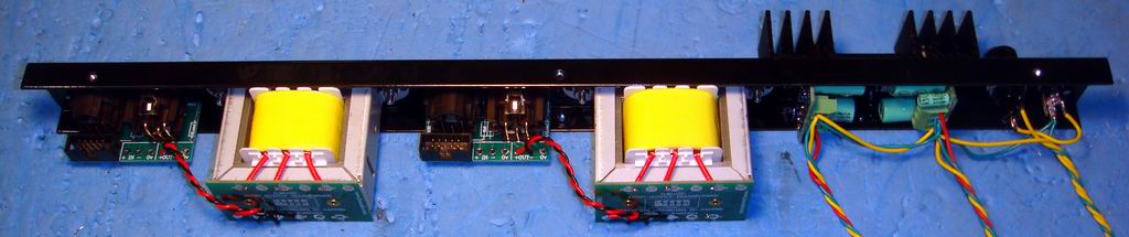
Back panel layout and wiring. (Note heatsink is no longer used.)Nappe wrote:Ok thanks fornthe help. It doesntnseem like the pictures show the trex anywhere....?
Trex info on forum also here
http://www.jlmaudio.com/forum/viewtopic ... hilit=TREX
Sounds like a solder short between to pads on the 48v rail on that channel. Need to see photo of soldering under under GO between PLUS PCB.Ive got onenchannel running with led lights on but without connecting the lastnrednwire. The other channel is not working though. Ive testet the voltage from the trax to the channel, but when i connect it the power supply switches off. Isbthat because of a shortcircuit somewhere? At one time it worked for a short period but turned off once i switched on the 48v.
Any advicebon where and how to start testing?
Joe
JLM Audio
Capturing Audio without Injury
JLM Audio
Capturing Audio without Injury
-
Joe Malone
- Site Admin
- Posts: 2078
- Joined: Wed Jan 24, 2007 11:35 pm
- Location: Brisbane, Australia
- Contact:
Re: 1290 Build Thread
Sounds like solder short as mentioned above post. Does 470R look burnt or measure high value than 470R?Nappe wrote:i might have found the error. The 470 R sitting at the 48V is giving any reading when i try the meter on it. Could i take one of the others for instance the pad one and use it instead or do they all need to be there. Im thinking in terms of not using the pad switch untill i get a new 470R
Joe
JLM Audio
Capturing Audio without Injury
JLM Audio
Capturing Audio without Injury
-
Joe Malone
- Site Admin
- Posts: 2078
- Joined: Wed Jan 24, 2007 11:35 pm
- Location: Brisbane, Australia
- Contact:
Re: 1290 Build Thread
Sounds like metal tab of the TIP122 transistor is shorted to the metal back panel.Nappe wrote:Phew seems to be having all kinds of problems. I switched the resistance and got 48 up and runni g on both channels. Then i had sparks from the power connection at back panel and now when the jack is mounted in the back panel i have a shortcircuit and the dc suply turns off. If i unscrew the connector so it is isolated from the back panel i do have lights in all leds. I have no idea why. Despretely need som help on this one.
When i measure voltage i get 48 v. Both before and after the trex. Is this the right voltage or do i need to turn the 5k trim down until i get 24v?
Check you have the very important insulator grey silicon stick on washer and white bush fitted correctly with the bolt and check with meter that the TIP122 and metal chassis are not shorted with a ohmmeter?
Joe
JLM Audio
Capturing Audio without Injury
JLM Audio
Capturing Audio without Injury
Re: 1290 Build Thread
Hi Joe,
I'm using the Carnhill VTB9049 as output transformer for the macro 1290 kits.
A wile ago when I was digging for a neve type pre diy kit, I saw in the EZ1290 assembly guide that they use a .01uf cap and a 1k5 resistor accross the output of the transformer(picture attach).
I was curious and tried it and it seems to take away some low end and add a bit of top end - seems like an eq and made me think to add a switch and have the eq option just in case .
What would you recomand for the macro1290-VTB9049 users, 9049 straight to the output or with the cap and resistor across?
Best regards,
Bogdan
You do not have the required permissions to view the files attached to this post.
-
Joe Malone
- Site Admin
- Posts: 2078
- Joined: Wed Jan 24, 2007 11:35 pm
- Location: Brisbane, Australia
- Contact:
Re: 1290 Build Thread
The Zobel circuit made from 0.01uF cap and 1k5 resistor was to flatten out the peak in the high frequency that the original LO1166 transformer when it was not driving a 600ohm load. All the Carnhill VTB9049 that I have tested do not have this peak but adding the zobel makes only a slight difference in the high frequency. It should not affect the low end at all. I would just choose which ever you like the sound of best or add a switch if you want.bsatriani wrote:Hi Joe,
I'm using the Carnhill VTB9049 as output transformer for the macro 1290 kits.
A wile ago when I was digging for a neve type pre diy kit, I saw in the EZ1290 assembly guide that they use a .01uf cap and a 1k5 resistor accross the output of the transformer(picture attach).
I was curious and tried it and it seems to take away some low end and add a bit of top end - seems like an eq and made me think to add a switch and have the eq option just in case .
What would you recomand for the macro1290-VTB9049 users, 9049 straight to the output or with the cap and resistor across?
Best regards,
Bogdan
Joe
JLM Audio
Capturing Audio without Injury
JLM Audio
Capturing Audio without Injury
Re: 1290 Build Thread
Hi Joe,
Building my dual 1290 kit here and I have a question about the power switch PCB:
Should I not install the included 4007 diode? (It says "not fitted" on the PDF, but I'm double checking I understand that correctly.)
also, just a general build procedure question:
the LED needs to be installed in the front panel before soldering. Do you recommend pulling the front panel off from the side and bottom panels to do this? Is it best to remove front and back panels when attaching PCBs and then do wiring? Or wire everything up, then attach components with panels in place? I imagine either way might work, mainly I'm wondering which way you'd do it.
Thanks Joe,
Dan
-
Joe Malone
- Site Admin
- Posts: 2078
- Joined: Wed Jan 24, 2007 11:35 pm
- Location: Brisbane, Australia
- Contact:
Re: 1290 Build Thread
The 1N4007 diode is only needed for ac powering so can be fitted or not for DC power like the 1290 kit uses. So as long as the diode is put on the correct way it will not matter either way.friesdan wrote:Hi Joe,
Building my dual 1290 kit here and I have a question about the power switch PCB:
Should I not install the included 4007 diode? (It says "not fitted" on the PDF, but I'm double checking I understand that correctly.)
Since we are assembling the case as we build our 1290 kits it is done in pieces. But most 1290 kit builders say they only remove the lid. But if you need more access all parts of the case come off with just a couple of screws.also, just a general build procedure question:
the LED needs to be installed in the front panel before soldering. Do you recommend pulling the front panel off from the side and bottom panels to do this? Is it best to remove front and back panels when attaching PCBs and then do wiring? Or wire everything up, then attach components with panels in place? I imagine either way might work, mainly I'm wondering which way you'd do it.
Thanks Joe,
Dan
Joe
JLM Audio
Capturing Audio without Injury
JLM Audio
Capturing Audio without Injury
Re: 1290 Build Thread
Hi Joe,
Thanks for your help so far. I reached a point where I could use your help again.
I wired all but the last red wires on the 2 channels, and adjusted the TREX trim pots for 24v (holding the black probe from my DMM on the middle green wire) terminal, and the red probe on the (future red wire) terminal. I also noticed 48-48.5 volts were on the yellow wire terminals.
then I connected the 2 red wires - and my left channel is showing 22.5v, which I assume I should trim back to 24v with the trim pot. However, the right channel is only showing about 1.21 volts. So I guess there's something wrong somewhere in that channel.
I double checked all wire connections with the DMM from terminal to terminal, comparing notes on both channels, and I can't find a difference there.
Where to next?
Swap the FET DIs?
FWIW, the go-between which was potentially problematic because of the lack of gap between the transformer and PCB is on the left (working) channel.
Thank you,
Dan
I used some brown wire when I ran out of green. please forgive this newb the messy wiring.
EDIT:
I swapped around DIs, transformers, and main 1290 boards (just not the go-betweens) - and found no change. Then I swapped TREX boards, and found that the problem followed this TREX board. I'm enclosing pictures. Any ideas? Thanks!
You do not have the required permissions to view the files attached to this post.
-
Joe Malone
- Site Admin
- Posts: 2078
- Joined: Wed Jan 24, 2007 11:35 pm
- Location: Brisbane, Australia
- Contact:
Re: 1290 Build Thread
With 0v and 48v connected to that TREX and nothing else what volts do you get out of the TREX?friesdan wrote:
EDIT:
I swapped around DIs, transformers, and main 1290 boards (just not the go-betweens) - and found no change. Then I swapped TREX boards, and found that the problem followed this TREX board. I'm enclosing pictures. Any ideas? Thanks!
Can you adjust the volts out at all with no load?
Did the 500mA slow blow fuse blow?
Or did the power supply go into hiccup mode (front power led will flash on and off)?
What part number is on the transistor in that TREX? TIP122?
With the other TREX you will get a bit of voltage sag when the 1290 PCB is loaded onto the TREX. Just trim the voltage up to 24v once 1290 PCB is connected to the TREX output.
Joe
JLM Audio
Capturing Audio without Injury
JLM Audio
Capturing Audio without Injury
Re: 1290 Build Thread
Quoting:
I get 24v, as I trimmed it to that using the trim resistor - see pic.
So I guess this answers question #2 - yes, without the 1290 connected, I adjusted the voltage from about 21 up to 24 if I remember right.
The fuse didn't blow, but I swapped it out with no change.
The power led doesn't flash.
the part number is TIP122, same as the other one.
Now that I've pulled both TREX boards off the back panel, I can feel the other working one heating up quite a bit when I power up. The problematic one doesn't heat up.
Thanks
Hey Joe,With 0v and 48v connected to that TREX and nothing else what volts do you get out of the TREX?
Can you adjust the volts out at all with no load?
Did the 500mA slow blow fuse blow?
Or did the power supply go into hiccup mode (front power led will flash on and off)?
What part number is on the transistor in that TREX? TIP122?
I get 24v, as I trimmed it to that using the trim resistor - see pic.
So I guess this answers question #2 - yes, without the 1290 connected, I adjusted the voltage from about 21 up to 24 if I remember right.
The fuse didn't blow, but I swapped it out with no change.
The power led doesn't flash.
the part number is TIP122, same as the other one.
Now that I've pulled both TREX boards off the back panel, I can feel the other working one heating up quite a bit when I power up. The problematic one doesn't heat up.
Thanks
You do not have the required permissions to view the files attached to this post.