MAC Rack kit Build Thread from October 2023 with slow attack led

Support for JLM Audio Kits

Moderator: Joe Malone

User avatar
Joe Malone
Site Admin
Posts: 2081
Joined: Wed Jan 24, 2007 11:35 pm
Location: Brisbane, Australia
Contact:

MAC Rack kit Build Thread from October 2023 with slow attack led

Post by Joe Malone »

UNDER CONSTRUCTONImage
Comp has new pull switches for threshold to activate the slow attack feature with orange led on front panel
Final led colours are red for link and green for power on. (Not the blue and green as shown)

MAC RACK KIT Build Thread using MAC500SC & MACPOT kits like our LA500A comps so has very little wiring to do

Dingo-T build map https://jlmaudio.com/builds/maps/dINgO-T.html

dINgO-T schematic at the link below http://www.jlmaudio.com/dingo/dINgOv4 f ... ematic.pdf

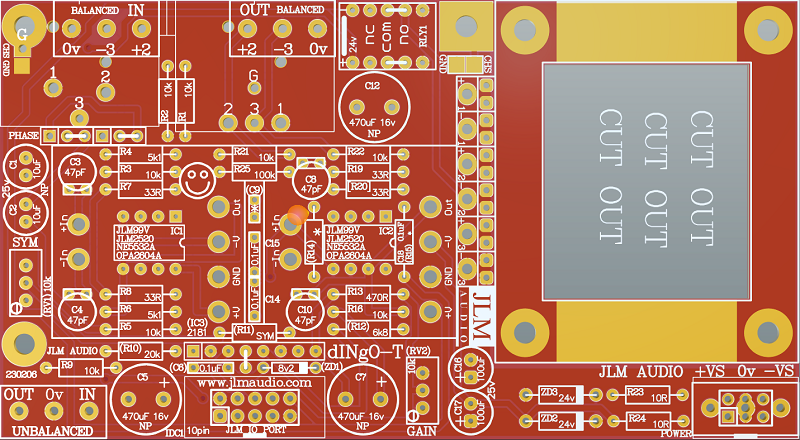
Blank dINgO-T PCB with full overlay shown (All parts numbers in () or [] brackets are not used with JLM99v opamps)
Image

MAC rack kit uses 2 x dINgO-T kits which are identical to dINgO but has output transformer pcb mounted on the PCB at the end of assembly
dINgO kit with all small parts shown. There will also be PCB XLR's in MAC rack kit.
Image

If you are not 100% with resistor colour codes use a multimeter to check values as you place the resistors
Image

Fit all resistors at once bending the legs sightly outwards to hold them in place. This helps to make sure no resistors are put in the wrong position.

Start with fitting of the 10k resistors into the PCB and bend the legs slightly outwards so they do not fall out when PCB is turned over.
Image
Image
Image

Fitting of the 33R resistors
Image
Image

Fitting of the 5k1 resistors
Image
Image

Fitting of the 10R resistors
Image
Image

Fitting of the 470R resistor
Image
Image

Turn over PCB on flat surface and solder and trim all resistors legs
Image
Image
Image
Image

Fit the two 24v zener diodes with stripes lined up with stripe on PCB and solder and trim legs
Image
Image
Image
Image
Image

Fit the 4 x 47pF ceramic caps folded flat to the PCB and solder and trim legs
Image
Image

Fit the 3 x 100nF mono caps with one folded flat to the PCB and solder and trim legs
Image
Image
Image
Image
Image

Fit the 2 x gold pin sets to the PCB and solder. Best to solder one pin on each and check if they are sitting straight before soldering all pins.
Image
Image
Image

Fit the 2 x 10uF & 2 x 100uF electro caps the check way around to the PCB and solder and trim legs. (+leg is the long leg of the cap)
Image
Image
Image
Image

Fit 2 x 10pin IDC headers to the PCB and solder and trim legs.
Image
Image
Image
Image
Image
Image
Image
Image
Image
Image
Image

Fit 24v relay to the PCB and solder and trim legs. Make sure stripe on relay matches stripe on PCB
Image
Image
Image
Image

Fit 4 x 470uF 16v Non Polar electro caps to the PCB and solder and trim legs. These are Non Polar so can be fitted either way around.
Image
Image
Image

Fit 2 x 3way terminal block to the PCB and solder and trim legs.
Image
Image

Fit 12 pins for the 2 x JLM99v opamps to the PCB and solder and trim legs.
Image
Image
Image
Image
Image
Image
Image
Image
Image
Image

Fit Male and Female XLR to the PCB and solder and trim legs. There maybe left over 3 way terminal blocks in the kit.
Image
Image

Trim side of Female XLR with sidecutters as shown
Image
Image
Image
Image
Image
Image
Image
Image
Image

Fit input polarity jumpers as shown for correct phase.
Image
Image

Fit 2 x JLM99v opamps to the 12 sockets on the PCB
Image

Fit ground link jumper beside XLR. Thid dINgO is built and ready. Build second dINgO and then move on to MAC PCB kits.
Image
Image
Image

Image

THE LA500SCv3 PCB is the MAC PCB but with no hand wiring and slow attack parts added

NEW LA500SCv3 PCB has extra MAC part so no meter wiring is needed in MAC rack kits
and some extra holes under U1 & U2 optos which are not used for now

Image

MAC schematic at the link below is the same.
http://www.jlmaudio.com/MAC/MACSCH.pdf

LA500SCv3 PCB parts kit
Image

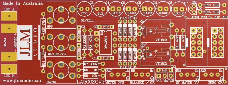
LA500SCv2 PCB. PCB overlay has all values and there are no options.
so PCB can be assembled directly from overlay.
Image

Fit all 8 x BAT85 diodes with there Cathode POLARIZED black stripe matching the white stripe on the MAC PCB overlay
Image
Image

Solder all BAT85 diodes while holding PCB firmly upside down on flat surface. Make sure none of the center close pads are NOT shorted together.
Image

Cut all diodes legs off at top of the solder joint and double check no solder joints missed soldering or are shorted together.
Image

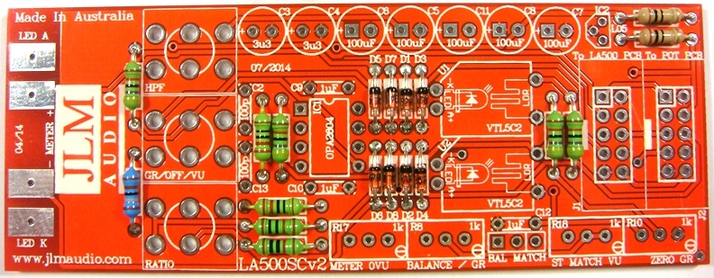
If you are not 100% with resistor colour codes use a multimeter to check values as you place the resistors
Image

Fit all resistors at once bending the legs sightly outwards to hold them in place.
This helps to make sure no resistors are put in the wrong position.
Image

Solder all resistors while holding PCB firmly upside down on flat surface.
Cut all resistor legs off at top of the solder joint and double check no solder joints missed soldering.
Image

Fit and solder DIP8 socket in other opamp position. Make sure the POLARIZED socket matches the PCB overlay.
Image
Image

Fit and solder 3 x 1uF MONO caps in place.
Image
Image
Image

Fit 2 x 100pF ceramic caps in place.
Image
Image

Fit and solder IDC headers in the POLARITY shown. Do not reverse. Triangle on header indicates pin 1 which is the square pad on the PCB.
Image

The front opening in the IDC headers should both now be facing as shown below.
Image
Image
Image

Fit and solder Electro caps to PCB. The 5 x 100uF caps are POLARIZED so must have there long positive leg fitted to + marked on PCB overlay.
Image
Image
Image
Image

2 x 3.3uF acaps are NON polar types so can go in either way around on the PCB.
Image
Image
Image
Image
Image

Fit and solder 4 trim pots as shown 1k = 102 code. Place pot so trim screw is in corner shown below
Image
Image
Image
Image
Image
Image

Fit and solder 3 pin header as shown below
Image
Image

Fit shunt to the 2 pins to the left
Image
Image

Fit and solder 78L05 5v regulator as shown below
Image
Image

Fit and solder NSL32 optos as shown below. Short legs are LED & Long legs are LDR on NSL-32.
The NSL32 Cathode has a dot marked on the case which goes to -K. Be gentle with the wire legs on the opto when shaping them for the PCB.
Note: If you are building a stereo matched pair. Fit the 2 optos in the plastic bag marked U1 into the U1 position on each separate PCB and same for the bag with the U2 pair.
If building just one comp use the 2 optos in the bag and either opto can go into U1 or U2.

Image
Image
Image

Plug in OPA2604AP opamp the correct way around as shown below and put the built LA500SCv2 and the 3 switches left over back in the plastic bag and move on to the LA500POTv2 kit.
Image
Image

Image

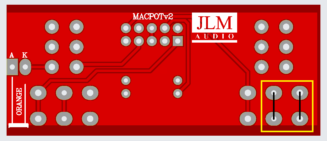
Note LA500POT PCB has been replaced with dedicated MACPOTv2 (needs 2 jumper wires added) & now MACPOTv3
Just build the MACPOT pcbs as their overlay shows as no mods or changes are needed.
Image
MACPOTv3 has the 2 missing 0v ground on the makeup pot pins fixed so the 2 jumpers are not needed.

LA500POTv4 kit Custom build photos for MAC RACK kit

Image

Start with fitting of the two 12k resistors into the PCB and bend the legs slightly outwards so they do not fall out when PCB is turned over.
Image
Image
Image
Image
Image

Fit 10 pin IDC header as shown below
Image
Image
Image
Image
Image
Image
Image

Fit 2 x 0ohm link resistors as shown below
Image
Image
Image
Image

Cut off locate tabs on pots and fit as shown below
Image
Image
Image
Image
Image
Image
Image
Image
Image

Image

Bolt all pots and switches in place on the front panel. Pots must have there locate tags cut off as shown earlier on this page.
Switches should have the rear nut wound about 2mm up the thread and washer and lock washer go on the behind the front panel so when fitted to front panel only just enough thread for the front nut is left. This makes the fornt panel look correct and gives the length needed for mounting the MAC pcb on the end of the long switch legs.
Image
Image
Image
Image
Image
Image

Image
Image
Image
Image
Image
Image
Image
Image
Image
Image
Image
Image
Image
Image
Image
Image
Image
Image
Image
Image
Image
Image
Image
Image
Image
Image
Image
Image
Image
Image
Image
Image
Image
Image
Image
Image
Image
Image
Image
Image
Image
Image
Image

The photos below show the old mac pcbs in the original mac build thread but the ribbon cable works the same.
Plugs ribbon into the centre IDC10 on the dingo pcb to the IDC10 connector not on the edge of LA500SC pcb and then to the MAC link pcb.
(LA500SC pcb edge IDC10 is used by LA500POT pcb ribbon cable)
Image
Image
Image
Image
Image
Image
Image
Image
Image
Image

Compressor setup procedure
1. Set MAC to Threshold pot fully CCW, Makeup pot to CCW. Ratio switch to 3:1, Meter switch to VU, HPF switch to FLAT.
2. Apply 1kHz tone to MAC input so you have the reference level of +4dBu (1.23vac) on the MAC output between pin 2 & 3 of the XLR.
3. Or plug MAC output into VU or PPM meter that is calibrated to 0VU = +4dBu. If voltage not correct level adjust 1kHz generator level until correct.
4. Adjust meter 0VU trim pot for the desired level of 0VU on the meter.
5. Switch Meter switch to GR and adjust Zero GR trim pot for 0VU on the meter.
6. Switch back to VU and meter should be reading 0VU and turn up Threshold pot until you have -5dB on the meter.
7. Switch Meter switch between GR and VU and adjust the Balance trim pot until the same reading is seen in both GR and VU.
8. Check that with both channels set the same and link switch on meters both still read -5dB. If not realign both comps again.
Joe :-)
JLM Audio
Capturing Audio without Injury

saxmonster
Posts: 32
Joined: Wed Jan 02, 2013 10:50 pm

Re: MAC Rack kit Build Thread from October 2023 with slow attack led

Post by saxmonster »

Hi Joe,
I have been working on the new transformer board and love the new layout. Just wanted to make sure the components on the right of this picture will not be used on this pcb version. Since the 2 pin and jumper are not being used on the ground and chassis like the older board had should I solder the two pads together?
ED233B21-1A5F-411D-A03A-2BA0C0AF1E97.jpeg
You do not have the required permissions to view the files attached to this post.

User avatar
Joe Malone
Site Admin
Posts: 2081
Joined: Wed Jan 24, 2007 11:35 pm
Location: Brisbane, Australia
Contact:

Re: MAC Rack kit Build Thread from October 2023 with slow attack led

Post by Joe Malone »

saxmonster wrote:
Sun Jan 14, 2024 4:12 am
Hi Joe,
I have been working on the new transformer board and love the new layout. Just wanted to make sure the components on the right of this picture will not be used on this pcb version. Since the 2 pin and jumper are not being used on the ground and chassis like the older board had should I solder the two pads together?

ED233B21-1A5F-411D-A03A-2BA0C0AF1E97.jpeg
That looks correct. Yes solder join the 2 ground points together. One next to the input XLR and one next to the L bracket so 0v is connected to the chassis well. Fit the 2 plug on jumpers to the correct spots on the 6 gold pins and leave out the 99v opmps for now.

To be super safe and double-check on power up. Only connect the 2 dingo-T pcb to power with no 99v opamps and no ribbon cables to the front pcbs plugged in. Then power up and check you have +/-24v at the 4 opamp power pins with a multimeter. If so turn off and fit the 99v opamps and retry power. If the power led on the rack or the power supply flash there is a short somewhere. If the power light stays on then power down and connect one dingo-T to the ribbon cable to the front pcbs and power up. If the power led flashes turn off and check that NE5532A is plugged in the correct way around and 78L12 & 79L12 are not reversed as these are the most common faults and best checked before powering on. If the power light stays on check meter lights up when switched VU and GR. If all looks good turn the power off and plug in the second ribbon channel to the front panel and check for the same. If all good leave powered up and lid sitting on the top for 30 minutes to fully warm up and then do the alignment. Usually best to do alignment and use the compressor and then do a second check alignment before fitting the lid finally.
Joe :-)
JLM Audio
Capturing Audio without Injury

saxmonster
Posts: 32
Joined: Wed Jan 02, 2013 10:50 pm

Re: MAC Rack kit Build Thread from October 2023 with slow attack led

Post by saxmonster »

Thanks for the info Joe.

Ok I did add power and I have 23.88 volts at the + 24 volts and 23.87 at the -24 volts side.

What are the screw types on the back side of case. I had an issue with the ribbon cable being loose on the pot board and I had to take it off from the front, would have been easier if I could get it from the bottom.

On the MACPOTv2 PCB I have, do I need to add the jumpers that you talk about in this thread on the C20K pot / makeup gain side of the PCB? It talks about the jumpers but then says build as is, lol. I added jumpers the to the legs of the pot as shown in your pic of the pcb. I forget what I did in my original LA500 slow attack mod, errr my mind is shot.

Where can I read up on what the Mac link pcb does. If I have that engaged do I still need to pull the makeup knobs out?

Thanks for the great support.

saxmonster
Posts: 32
Joined: Wed Jan 02, 2013 10:50 pm

Re: MAC Rack kit Build Thread from October 2023 with slow attack led

Post by saxmonster »

I started the calibration procedure. I was able to get both meters to read zero for the VU and for GR settings. I was also able to get the -5 to be balanced on both meters between the VU and GR settings. That went pretty smoothly. I will have to read up on linking them though as that is not working correctly.

This is weird though - Sending a signal out of 2 different outputs from my DAW Channel A is getting 1.23 VAC at the input and Channel B is getting 1.231VAC at the input. That is as close of a relationship I could get my daw to send out. Here is the weird part with the settings of 1:3 ratio, VU and Flat I am getting 1.225VAC at the output of channel A which is a difference of .005 and 1.171VAC at the output of Channel B which is a difference of .06VAC. Is a loss of .005 and .06 bad as the signal is ran through the unit? How can I get these closer. Also when I have the meters off both channel outputs read 1.167 which is slightly bigger difference of .063VAC.

Please let me know if everything seems ok with these numbers so I can move on. I will start looking at the 2016 build thread as I think I saw some info about the linking feature in it. I need to understand that better and then button it up.

Thanks
-Scott
Last edited by saxmonster on Sat Jan 20, 2024 5:35 pm, edited 1 time in total.

saxmonster
Posts: 32
Joined: Wed Jan 02, 2013 10:50 pm

Re: MAC Rack kit Build Thread from October 2023 with slow attack led

Post by saxmonster »

I just check the link calibration from the other build thread and all seems ok. The meters do move ever so slighlty towards the center link switch. Channel A move toward 0DB and Channel B moves toward -6DB. When added together they move maybe the a quarter of a DB total. I don't think I would ever hear the difference but should they move at all? Should I try to make them not move at all if I am going to be using this on my 2 buss?

Thanks
-Scott

saxmonster
Posts: 32
Joined: Wed Jan 02, 2013 10:50 pm

Re: MAC Rack kit Build Thread from October 2023 with slow attack led

Post by saxmonster »

Here are some pics of the meters after calibration with GR on and the LINK switch ON. They both were on -5db before I turned the link switch on. let me know what you think. Is this within spec?
Photo Jan 21 2024, 4 46 13 PM.jpg
Photo Jan 21 2024, 4 46 20 PM.jpg
Not sure if these output spec look ok

Channel A 1.23VAC at input Channel B 1.231VAC at input

output w/ power off A= 1.171VAC B= 1.175VAC

output w/ power on
meters off A= 1.167VAC B= 1.165VAC

output w/ -0db GR A= 1.225VAC B= 1.171VAC

output w/ -0db VU A= 1.25VAC B= 1.171VAC

output w/ -5db VU A= .819VAC B= .825VAC

output w/ -5db GR A= .818VAC B= .825VAC

output w/ link switch on A= .803VAC B= .811VAC
You do not have the required permissions to view the files attached to this post.

User avatar
Joe Malone
Site Admin
Posts: 2081
Joined: Wed Jan 24, 2007 11:35 pm
Location: Brisbane, Australia
Contact:

Re: MAC Rack kit Build Thread from October 2023 with slow attack led

Post by Joe Malone »

saxmonster wrote:
Mon Jan 22, 2024 4:11 am
Here are some pics of the meters after calibration with GR on and the LINK switch ON. They both were on -5db before I turned the link switch on. let me know what you think. Is this within spec?
Photo Jan 21 2024, 4 46 13 PM.jpg
Photo Jan 21 2024, 4 46 20 PM.jpg

Not sure if these output spec look ok

Channel A 1.23VAC at input Channel B 1.231VAC at input

output w/ power off A= 1.171VAC B= 1.175VAC

output w/ power on
meters off A= 1.167VAC B= 1.165VAC

output w/ -0db GR A= 1.225VAC B= 1.171VAC

output w/ -0db VU A= 1.25VAC B= 1.171VAC

output w/ -5db VU A= .819VAC B= .825VAC

output w/ -5db GR A= .818VAC B= .825VAC

output w/ link switch on A= .803VAC B= .811VAC
Yes that is fine calibration as it is under +/-1dB offset. So on music there will be even less difference.
Joe :-)
JLM Audio
Capturing Audio without Injury

saxmonster
Posts: 32
Joined: Wed Jan 02, 2013 10:50 pm

Re: MAC Rack kit Build Thread from October 2023 with slow attack led

Post by saxmonster »

Does anyone know how I can get the two channels a little bit closer in measurements. It seems that I have to throw a lot more signal at channel B than A by looking at the Volts AC. VAC. Almost .5 DB extra on the fader coming out of my DAW to get 1.23 VAC on the B Channel. Is it the output pots that are off because they are not matched pairs? I also noticed that I have to turn one of the threshold knobs up more (I wanna say ch B) to get to the -5db. I know that this is an LA2A LA3A type of compressor and stereo pairs of these are not totally in sync and equal but I would just feel better if I could get them closer. All of my calibrations look great and I even got the needle to not move when I switch the link on. I plan on using it on my 2buss and also for mastering if possible. I guess I will just have to use my ears more and really train myself in critical listening and not just going by having the knobs is the same spots, lol. I know with actual music it will be hard to hear these difference but mathematically / measurement wise it bugs me. See measurements below. Any thoughts would be helpful.
-Scott
MAC Opto VAC Differences between Channels .png
You do not have the required permissions to view the files attached to this post.

User avatar
Joe Malone
Site Admin
Posts: 2081
Joined: Wed Jan 24, 2007 11:35 pm
Location: Brisbane, Australia
Contact:

Re: MAC Rack kit Build Thread from October 2023 with slow attack led

Post by Joe Malone »

saxmonster wrote:
Fri Feb 02, 2024 2:55 pm
Does anyone know how I can get the two channels a little bit closer in measurements. It seems that I have to throw a lot more signal at channel B than A by looking at the Volts AC. VAC. Almost .5 DB extra on the fader coming out of my DAW to get 1.23 VAC on the B Channel. Is it the output pots that are off because they are not matched pairs? I also noticed that I have to turn one of the threshold knobs up more (I wanna say ch B) to get to the -5db. I know that this is an LA2A LA3A type of compressor and stereo pairs of these are not totally in sync and equal but I would just feel better if I could get them closer. All of my calibrations look great and I even got the needle to not move when I switch the link on. I plan on using it on my 2buss and also for mastering if possible. I guess I will just have to use my ears more and really train myself in critical listening and not just going by having the knobs is the same spots, lol. I know with actual music it will be hard to hear these difference but mathematically / measurement wise it bugs me. See measurements below. Any thoughts would be helpful.
-Scott
MAC Opto VAC Differences between Channels .png
Are those out-of-alignment interface outputs going to drive the comp always? Y/N

Do you want to compensate in the MAC to fix the interface mismach)? Y/N

First, use a Y cable from one output of your interface to the inputs of the MAC so both channels have identical input level +4dBu (1.23vac).

Check with VU/OFF/GR in off that you have identical output levels ? Y/N

With Threshold and Makeup fully CCW switch to VU and let me know the voltages you get on the left and right output?

If the voltages don't match turn off the comp and leave off for a while and measure the outside pins of the threshold and makeup pots still fully CCW.
(Like left threshold 95.76k and right threshold 102.54k and left makeup 9.33k and right makeup 11.11k. be as accurate as you meter shows)
Joe :-)
JLM Audio
Capturing Audio without Injury

saxmonster
Posts: 32
Joined: Wed Jan 02, 2013 10:50 pm

Re: MAC Rack kit Build Thread from October 2023 with slow attack led

Post by saxmonster »

If the voltages don't match turn off the comp and leave off for a while and measure the outside pins of the threshold and makeup pots still fully CCW.
(Like left threshold 95.76k and right threshold 102.54k and left makeup 9.33k and right makeup 11.11k. be as accurate as you meter shows)
Which ones are the outside pins, I think the pots have two rows of three pins right? Also the one pot has a bridge on it right?

User avatar
Joe Malone
Site Admin
Posts: 2081
Joined: Wed Jan 24, 2007 11:35 pm
Location: Brisbane, Australia
Contact:

Re: MAC Rack kit Build Thread from October 2023 with slow attack led

Post by Joe Malone »

saxmonster wrote:
Mon Feb 05, 2024 3:56 am
If the voltages don't match turn off the comp and leave off for a while and measure the outside pins of the threshold and makeup pots still fully CCW.
(Like left threshold 95.76k and right threshold 102.54k and left makeup 9.33k and right makeup 11.11k. be as accurate as you meter shows)
Which ones are the outside pins, I think the pots have two rows of three pins right? Also the one pot has a bridge on it right?
Yes pots are bridged so measure the furthest apart pair of pads. Not the centre pads. If you measure front outside and back outside pads they should be the same if you soldering is good.
Joe :-)
JLM Audio
Capturing Audio without Injury

saxmonster
Posts: 32
Joined: Wed Jan 02, 2013 10:50 pm

Re: MAC Rack kit Build Thread from October 2023 with slow attack led

Post by saxmonster »

Sorry but I am still confused on the inside / outside part. Before I pull these boards out because I can’t reach the front six soldering points cause they are covered by the case lip. Can I measure from the back 6 solder pads on each pot? Are these part of the switch or the potentiometer? I have circled in white what I think I should measure. I don’t think the jumpers should be measured anyways. I have the macpotv2 pcbs.
IMG_6893.jpeg
You do not have the required permissions to view the files attached to this post.

User avatar
Joe Malone
Site Admin
Posts: 2081
Joined: Wed Jan 24, 2007 11:35 pm
Location: Brisbane, Australia
Contact:

Re: MAC Rack kit Build Thread from October 2023 with slow attack led

Post by Joe Malone »

saxmonster wrote:
Mon Feb 05, 2024 1:51 pm
Sorry but I am still confused on the inside / outside part. Before I pull these boards out because I can’t reach the front six soldering points cause they are covered by the case lip. Can I measure from the back 6 solder pads on each pot? Are these part of the switch or the potentiometer? I have circled in white what I think I should measure. I don’t think the jumpers should be measured anyways. I have the macpotv2 pcbs. IMG_6893.jpeg
See attached. The back sections you have marked are the pull switch terminals. Front 6 pads are the dual pot terminals. If soldered correctly you should get the same value on the front two solder pads shown and the 2 solder pads behind them.
MACPOTv3 doesn't need the 2 jumpers in the yellow box.
MACPOT pot value test.png
You do not have the required permissions to view the files attached to this post.
Joe :-)
JLM Audio
Capturing Audio without Injury

saxmonster
Posts: 32
Joined: Wed Jan 02, 2013 10:50 pm

Re: MAC Rack kit Build Thread from October 2023 with slow attack led

Post by saxmonster »

Ok I now know what to measure now thanks so much. Here are the answers from the previous post.

Are those out-of-alignment interface outputs going to drive the comp always? Y/N.

No, it is just what I have available but now that I know there are discrepancies I will be checking all the outputs of the interface. Probably will upgrade it.

Do you want to compensate in the MAC to fix the interface mismach)? Y/N

No I will be sending it a balance stereo signal.

First, use a Y cable from one output of your interface to the inputs of the MAC so both channels have identical input level +4dBu (1.23vac).

I believed I tried this before but not sure if it was the signal going in that was not the same on each side or if it was the output of the Mac opto that was not equal and why I ditched it and went with the adjustable outputs of my interface to get the 1.23 vac. I will try it again and make sure I have 1.23 vac at both inputs.

Check with VU/OFF/GR in off that you have identical output levels ? Y/N
I have both channels of the opto receiving 1.23 VAC and the outputs of the opto are the same but they have dropped to 1.197 VAC.

With Threshold and Makeup fully CCW switch to VU and let me know the voltages you get on the left and right output?

Channel A has 1.246 VAC for output and Channel B has 1.190VAC

If the voltages don't match turn off the comp and leave off for a while and measure the outside pins of the threshold and makeup pots still fully CCW.
(Like left threshold 95.76k and right threshold 102.54k and left makeup 9.33k and right makeup 11.11k. be as accurate as you meter shows)

Channel A makeup is 9.26K Channel B Makeup is 9.64k a difference of .38k, Channel A Threshold is 26.62K Channel B Threshold is 25.76k a difference of .86k.


Thanks for all your help, sorry to be a PIA.
-Scott

Post Reply