Stereolab kit Build Thread
Posted: Mon Mar 11, 2019 9:55 pm
Stereolab kit
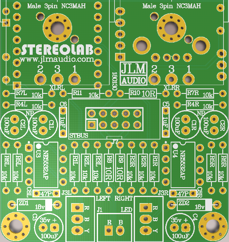
PCB TOP Build Map http://www.jlmaudio.com/builds/maps/ste ... opmap.html
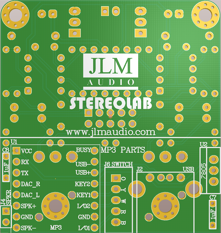
PCB BOTTOM Build Map http://www.jlmaudio.com/builds/maps/ste ... ommap.html
Stereolab schematic https://www.jlmaudio.com/Stereolab/STER ... ematic.pdf
Power from +/-9vdc to +/-18vdc into V+ 0v V- or fit 18v zeners and power with 36v between V+ & V- on STBUS header.
Unbalanced input
If 5k trimpots fitted to J3L & J3R unbalanced input is available at DAC_L and DAC_Rmarked on MP3 under pcb.
If no Trimpots fitted to J3L & J3R unbalanced input is available on J3L & J3R on B = Black wire and 0v ground on Y = Yellow.
JLM STBUS 10pin output (Same as on AMP HEAD, AMP HEAD II, STATTEN, Stereo IO kit etc)
Pin 1 Left + output
Pin 2 Left - output
Pin 3 & 4 V+
Pin 5 & 6 0v
Pin 7 & 8 V-
Pin 9 Right - output
Pin 10 Right + output
Balanced output also available on the XLR's
PCB TOP Build Map http://www.jlmaudio.com/builds/maps/ste ... opmap.html
PCB BOTTOM Build Map http://www.jlmaudio.com/builds/maps/ste ... ommap.html
Stereolab schematic https://www.jlmaudio.com/Stereolab/STER ... ematic.pdf
Power from +/-9vdc to +/-18vdc into V+ 0v V- or fit 18v zeners and power with 36v between V+ & V- on STBUS header.
Unbalanced input
If 5k trimpots fitted to J3L & J3R unbalanced input is available at DAC_L and DAC_Rmarked on MP3 under pcb.
If no Trimpots fitted to J3L & J3R unbalanced input is available on J3L & J3R on B = Black wire and 0v ground on Y = Yellow.
JLM STBUS 10pin output (Same as on AMP HEAD, AMP HEAD II, STATTEN, Stereo IO kit etc)
Pin 1 Left + output
Pin 2 Left - output
Pin 3 & 4 V+
Pin 5 & 6 0v
Pin 7 & 8 V-
Pin 9 Right - output
Pin 10 Right + output
Balanced output also available on the XLR's