PCB Component Build maps
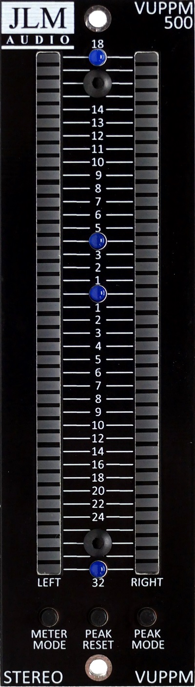
Display PCB
http://jlmaudio.com/builds/maps/VUPPM50 ... y_map.html
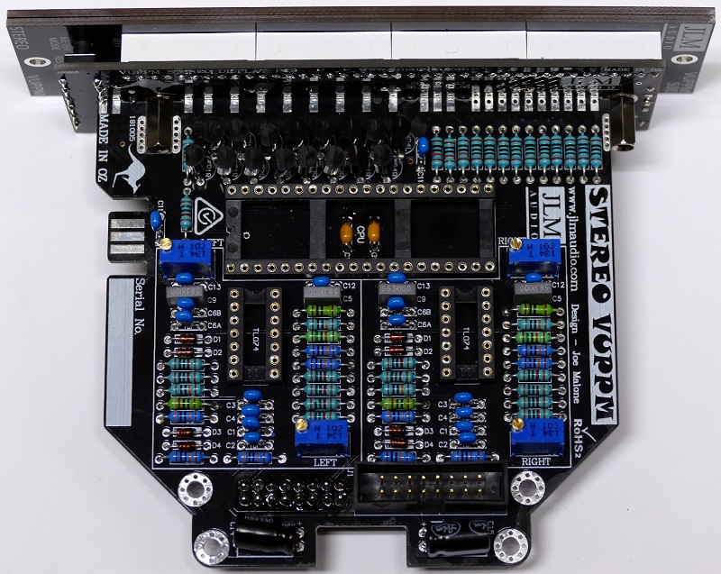
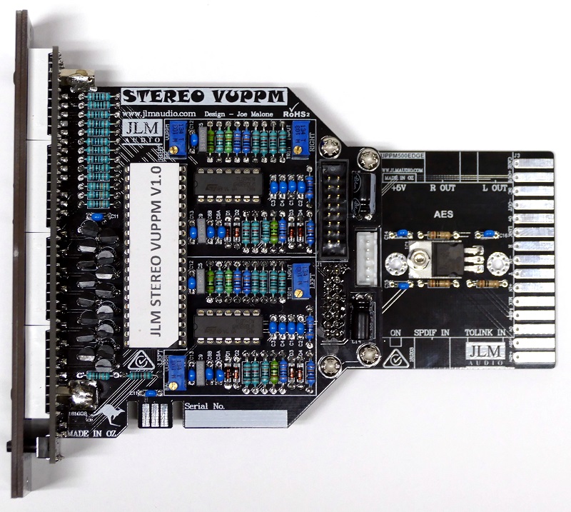
MAIN CPU PCB
http://jlmaudio.com/builds/maps/VUPPM500_map.html
500 EDGE PCB
http://jlmaudio.com/builds/maps/VUPPM50 ... nalog.html
500 EDGE PCB DIGITAL ADD ON OPTION (Build and test VUPPM500 as analog first then add on digital option)
http://jlmaudio.com/builds/maps/VUPPM50 ... gital.html
Test procedure Analog input
Plug in built VUPPM500 module.
Press Meter Mode and Peak Mode together to go into led test mode. This shows all green then all orange and then all red.
Press peak reset to set brightness level to LOW, MEDIUM, HIGH.
Press either Meter Mode and Peak Mode to leave led test mode.
Send in 1k tone at 0dFS or +18dBu to 500 Input for left and Output for right.
Set mode to VUPPM mode RED PPM with GREEN VU over the top.
Adjust Left and Right level trimpots so left and right 40th red led just light.
Adjust Left and Right VU/PPM trimpots so left and right green led just light. (40th led may make yellow depending on peak mode)
Test procedure Digital input
Plug in built VUPPM500 module.
Press Meter Mode and Peak Mode together to go into led test mode. This shows all green then all orange and then all red.
Press peak reset to set brightness level to LOW, MEDIUM, HIGH.
Press either Meter Mode and Peak Mode to leave led test mode.
Send in AES/EBU 1k tone at 0dFS into 500 Input.
Set mode to VUPPM mode RED PPM with GREEN VU over the top.
Adjust Left and Right level trimpots so left and right 40th red led just light.
Adjust Left and Right VU/PPM trimpots so left and right green led just light. (40th led may make yellow depending on peak mode)