Hey Joe
Is there a link that shows the db25 or jlm io port pin outs? I've searched all over but i can't find a definitive jlm io port schematic anywhere or at the very least a pcb which i can retrace the circuit backwards to figure it out myself.
Thanks
Dylan
Passive Controller Build Thread Ver 1 - 3
Moderator: Joe Malone
-
Joe Malone

- Site Admin
- Posts: 2081
- Joined: Wed Jan 24, 2007 11:35 pm
- Location: Brisbane, Australia
- Contact:
Re: Passive Controller Build Thread
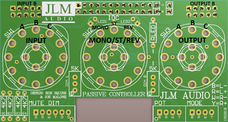
IDC header lays out so pin 1 (square solder pad) = pin 13 on IDC DB25 (pin 25 is not used on DB25 for tascom pinout). So if you have the red strip on ribbon cable to pin 1 IDC header and then fit 24 wire ribbon so red strip goes to pin 13 on IDC type DB25 you will have 4 inputs followed by 4 outputs running in 1 left right, in 2 left right, out 1 left right and out 2 left right.Rocinante wrote:Hey Joe
Is there a link that shows the db25 or jlm io port pin outs? I've searched all over but i can't find a definitive jlm io port schematic anywhere or at the very least a pcb which i can retrace the circuit backwards to figure it out myself.
Thanks
Dylan
pin 1 0v
pin 2 -in/out
pin 3 +in/out
pin 4 0v
pin 5 -in/out
pin 6 +in/out
etc
Joe 
JLM Audio
Capturing Audio without Injury
JLM Audio
Capturing Audio without Injury
Re: Passive Controller Build Thread
Joe
Unfortunately I don't have the ribbon cable and am gonna be connecting the ins to the summing bus of my mixer as well as an external in. The outs will be connected to some Regurgitators that I am using for my monitor outs. I have made another little diagram could you please check it for me. I hope it is right nd if it is wrong please know that it is the receiver and not the transmitter that was the problem.
Also output B and ext are additional external connections?
I'm gonna pick up another pcb for just a monitor controller cause this is so feature filled its perfect. And tidy.
AND THANKS!!!!!!!
-
Joe Malone
- Site Admin
- Posts: 2081
- Joined: Wed Jan 24, 2007 11:35 pm
- Location: Brisbane, Australia
- Contact:
Re: Passive Controller Build Thread
I deleted the wrong image link so others don't confused. IDC header number old on front row and even numbers on back row.Rocinante wrote:Joe
Unfortunately I don't have the ribbon cable and am gonna be connecting the ins to the summing bus of my mixer as well as an external in. The outs will be connected to some Regurgitators that I am using for my monitor outs. I have made another little diagram could you please check it for me. I hope it is right nd if it is wrong please know that it is the receiver and not the transmitter that was the problem.
Also output B and ext are additional external connections?
I'm gonna pick up another pcb for just a monitor controller cause this is so feature filled its perfect. And tidy.
AND THANKS!!!!!!!
LP- & LP+ are for the leds on the passive controller pcb for mono and rev when using a rotary switch on the PCB.
See image below for pinouts
All odd inputs are left and all even are right. So 1,2,3,4 are inputs and 5,6,7,8 are outputs.
Joe
JLM Audio
Capturing Audio without Injury
JLM Audio
Capturing Audio without Injury
Re: Passive Controller Build Thread
Thanks Joe I would have never figured that out. And so Out B and Ext in are additional in and out?
Re: Passive Controller Build Thread
Hey there Joe,
Is there any way to get a schematic for this pcb? Or at least a labeled graphic?
Is there any way to get a schematic for this pcb? Or at least a labeled graphic?

Re: Passive Controller Build Thread
okI have several questions as I´m about to order:
- Passive monitor controller pcb
- TASCAM / IDC to XLR / TRS IN & OUT PCB
- AMP Head
and would like to incorporate that into one monitor controller chassis.
Yes that will work fine.- I would like to use the AMP Head as 3rd Output, can I connect it directly via a 10-wire ribbon cable from the bus connector to the connector above switch 3 (same pin layout I guess)?
The +/-15v to 18v power for the amp head can be used to run the leds on the passive controller pcb by just fitting the resistors and leds (roughly 4k7 for +/-18v for normal brightness 3mm leds. )- I suppose the V+ V- is only used to power the LEDs on the passive monitor controller pcb?
PCb is 199mm x 31mm. XLR / TRS spacing is 25.4mm (1") If you want the third input use our stereio in pcb which has XLR/TRS on 25.4mm spacing as well and will plug into the other 10 pin header.- What are the dimensions of the TASCAM /IDC pcb and the distance between the XLR connectors?
Wire in and out together for + and use ground connection for - and it will work as the volume attenuator for the passive controller as long as the switch is a shorting make before break type.- I want to use a balanced 24-stepped attenuator instead of a volume pot, like in the following image, how can this be done/wired
Everything has an end but a sausage has two...
Re: Passive Controller Build Thread
Hi Joe and thanks for your Support!
The PCBs finally arrived and I´m searching for the rotary switches (shorting?).
Lorlin came into my mind but the four pins in the middle need to be bent to fit.
Is this intentional or did you have other switches in mind?
If so please give me a hint which switches to use as I´m having problems to find the open switches mentioned in Rob´s article.
Cheers
Eric
Everything has an end but a sausage has two...
-
Joe Malone
- Site Admin
- Posts: 2081
- Joined: Wed Jan 24, 2007 11:35 pm
- Location: Brisbane, Australia
- Contact:
Re: Passive Controller Build Thread
The PCB is made for the open frame 3 position 4 way non-shorting Alpha switches as they are long lasting.cromwell wrote:Hi Joe and thanks for your Support!
The PCBs finally arrived and I´m searching for the rotary switches (shorting?).
Lorlin came into my mind but the four pins in the middle need to be bent to fit.
Is this intentional or did you have other switches in mind?
If so please give me a hint which switches to use as I´m having problems to find the open switches mentioned in Rob´s article.
Cheers
Eric
We have them available on the JLM webshop at the link below.
https://www.jlmaudio.com/shop/rotary-sw ... -pole.html
Joe
JLM Audio
Capturing Audio without Injury
JLM Audio
Capturing Audio without Injury
Re: Passive Controller Build Thread
Hi Joe. I built the monitor controller + Vu buffer on the same unit. Everything is working perfect! But the DIM does nothing, i installed 5k resistors insted of the trimmers. Do you have any hints to troubleshoot this?
-
Joe Malone
- Site Admin
- Posts: 2081
- Joined: Wed Jan 24, 2007 11:35 pm
- Location: Brisbane, Australia
- Contact:
Re: Passive Controller Build Thread
The 5k trims just switch across the volume pot to limit the full volume. So at full volume 5k resistors would dim about 9dB.Ayguid wrote:Hi Joe. I built the monitor controller + Vu buffer on the same unit. Everything is working perfect! But the DIM does nothing, i installed 5k resistors insted of the trimmers. Do you have any hints to troubleshoot this?
Attach a photo here or send me a photo of your wiring to the dim switch so I can see what is going wrong.
Joe
JLM Audio
Capturing Audio without Injury
JLM Audio
Capturing Audio without Injury
Re: Passive Controller Build Thread
Is there a schematic available? Am I right in assuming that sw1 is the input switch & sw3 is output?
-
Joe Malone
- Site Admin
- Posts: 2081
- Joined: Wed Jan 24, 2007 11:35 pm
- Location: Brisbane, Australia
- Contact:
Re: Passive Controller Build Thread
The schematic is shown in parts in the original article link on the first page of this thread.Mjwever wrote:Is there a schematic available? Am I right in assuming that sw1 is the input switch & sw3 is output?
I added more labeling to overlay below to be more clear.
The Tascam DB25 has stereo input A & C and output A & C. Input B & output B are OFF position if the 10 pin STBUS connectors are not used.

Joe
JLM Audio
Capturing Audio without Injury
JLM Audio
Capturing Audio without Injury
Re: Passive Controller Build Thread
Thanks heaps Joe. Maybe a newbie question - how do you orient the switches on the board ie. where would pin 1 be?
-
Joe Malone
- Site Admin
- Posts: 2081
- Joined: Wed Jan 24, 2007 11:35 pm
- Location: Brisbane, Australia
- Contact:
Re: Passive Controller Build Thread
The rotary switches just need to line up with the overlay. So can go in either way around as long as they match the angle of the overlay and go in on the overlay side.Mjwever wrote:Thanks heaps Joe. Maybe a newbie question - how do you orient the switches on the board ie. where would pin 1 be?
Joe
JLM Audio
Capturing Audio without Injury
JLM Audio
Capturing Audio without Injury