Please read the Kraftwerk & AC/DC / Powerstation Threads first at the links below as it has step by step info and schematics.
They are the same as the V6 kits but with less rails. Kraftwerk kit is identical but has one less -V rail
Hi Joe,
We emailed a little about this. I thought it would be good to post here for others to see. A little clarification needed on the V6 I am just finishing up...
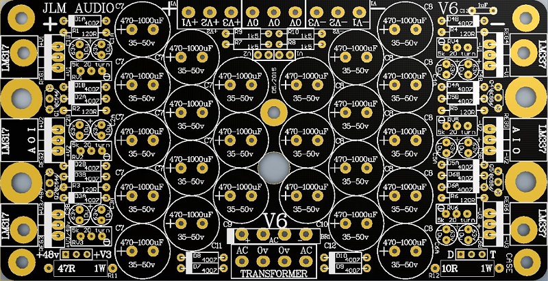
I am going to use the V6 to run a Barry Porter EQ. I put the V6 in a floor box. I had thought incorrectly that the big pad in the middle of the pcb, just above the hole for the bridge rectifier, was the central ground point. My V6 is actually grounding through the heat sink, which is screwed to the floor box. (The OV pads for the rails show 10R to ground, so I assume they connect to R12 before going to ground.) Is grounding through the heat sink screw pads the best arrangement?
The cable coming from the EQ has a 0V conductor coming from all the pcb's in the EQ, a 0V conductor coming from relay ground for an independent M/S matrix in the EQ, and a conductor from the EQ's chassis. Should I connect some or all of these to the 0V pads on the V6, or are some better going direct to the floor box chassis?
thanks,
Justin
skidmorebay wrote:Hi Joe,
We emailed a little about this. I thought it would be good to post here for others to see. A little clarification needed on the V6 I am just finishing up...
I am going to use the V6 to run a Barry Porter EQ. I put the V6 in a floor box. I had thought incorrectly that the big pad in the middle of the pcb, just above the hole for the bridge rectifier, was the central ground point. My V6 is actually grounding through the heat sink, which is screwed to the floor box. (The OV pads for the rails show 10R to ground, so I assume they connect to R12 before going to ground.) Is grounding through the heat sink screw pads the best arrangement?
The cable coming from the EQ has a 0V conductor coming from all the pcb's in the EQ, a 0V conductor coming from relay ground for an independent M/S matrix in the EQ, and a conductor from the EQ's chassis. Should I connect some or all of these to the 0V pads on the V6, or are some better going direct to the floor box chassis?
thanks,
Justin
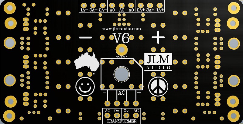
All audio 0v connections from the EQ box go to 0v terminals on V6 PCB which are all connected on the PCB. The 10R on the V6 connects this 0v to chassis earth via the heatsink. Only connection to the chassis earth should be mains ground wire for power cable. And wire from that star point taking this mains ground from the power supply box to the EQ box.
Hi Joe,
Could you give a bit of a run down on the jumpers? I can't find this info anywhere...
I'm trying to get V3 putting out 48v (this part seems obvious..) and one more rail of +/-17v (so I'm guessing combining V1 and V2 rails?).
Thanks
Lachie wrote:Hi Joe,
Could you give a bit of a run down on the jumpers? I can't find this info anywhere...
I'm trying to get V3 putting out 48v (this part seems obvious..) and one more rail of +/-17v (so I'm guessing combining V1 and V2 rails?).
Thanks
For 48v
if using 2 x 18vac transformer jumpers 48v & T
if using 2 x 24vac transformer jumpers 48v & D
Fit V1 and V2 jumpers so you can adjust and set V1 & V2 voltage trim pots.
When +/-V1 and +/-V2 are set to +/-17v then remove V1 & V2 jumper now if one power rail shuts down it will shut down it opposite rail.
If combining V1 & V2 rails with 0.1R 1W to 5W resistors to double the current. Fitting a jumper to centre 2 pins of the V1 & V2 4 pins will link the shutdowns together which is a good idea.
just to clarify on combining the rails in your last example. Which resistors are getting subbed out for 5w? I can't see any .1R resistors on the PCB.
Thanks
Hi Lachie
The 0.1R 5W resistors are added in series with the outputs and are not on the V6 pcb at all. They are easily superglued to the chassis or to each other.
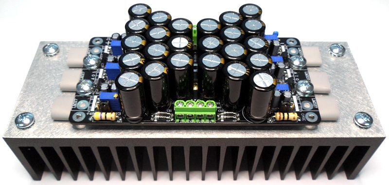
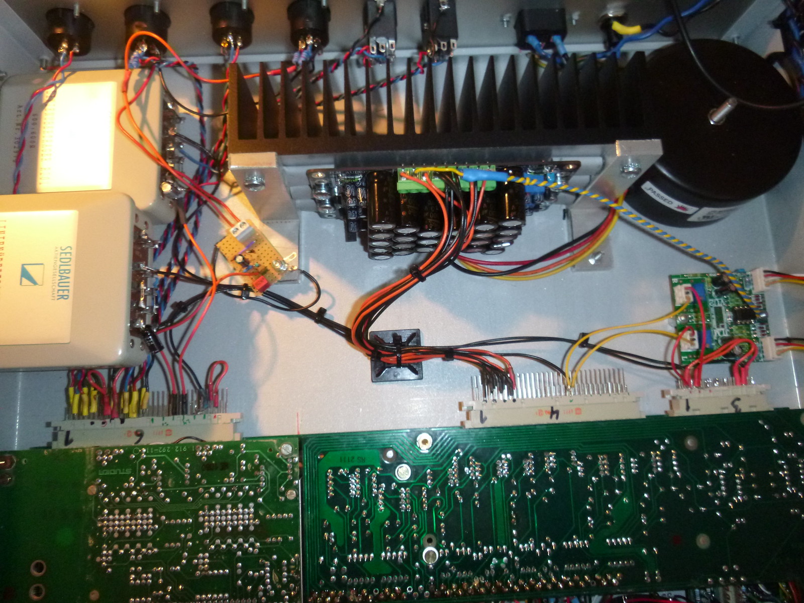
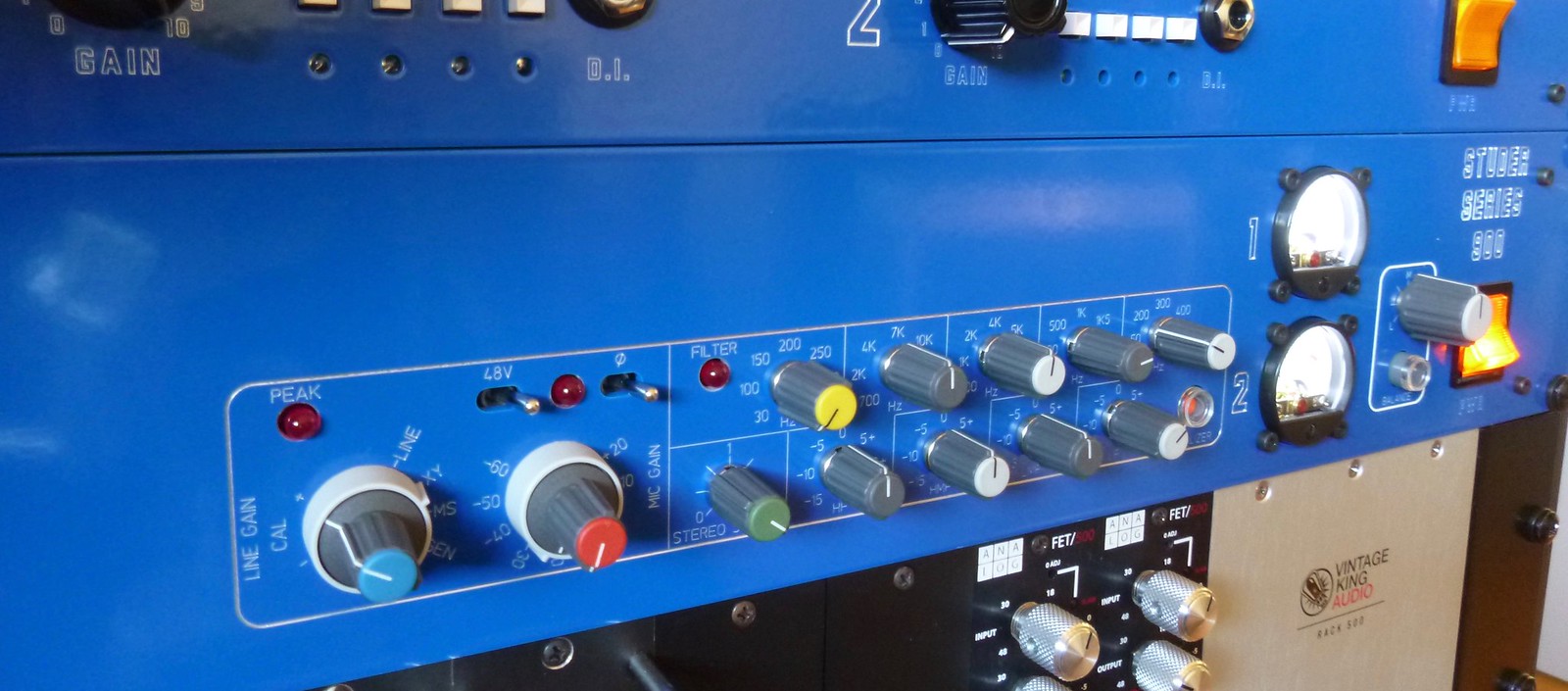
I've racked a Studer 900 stereo channel using the V6 Power Supply. worked out perfectly!
thanks for the support, Joe!
Nice work man! everythng is really neat. This inspired me to go for this project I wish i had that studer 900 stereo channel to try it on though :droolingface: :p it kind of looks like a maag EQ because of the colors. (love the Air band)
How much tme it took you to finish the project?
Beatsbooster is designed to help you with the decision-making when buying your first best headphones under $500. I highlight the products which are the best value, as well as the top sellers.
densom wrote:Hi Joe,
It would be great if this V6 build thread could be updated to be as comprehensive as the powerstation and kraftwerk build threads.
Cheers
OK will do. It is very similar to the AC/DC, Powerstation and Kraftwerk.
Feel free to ask any questions you have in the meantime while building the kit either on here or by email.
Joe Malone wrote:It is very similar to the AC/DC, Powerstation and Kraftwerk.
I had a bit of a look through the other build threads and picked up some good tips. In particular, I didn't realise that the secondaries should be wired out of phase to maximise the voltage the refresh rate of the capacitors. Makes sense. Will definitely let you know if I have any questions once I get started. Thanks Joe.