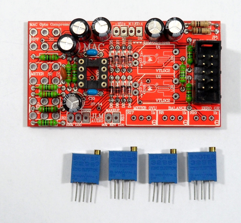
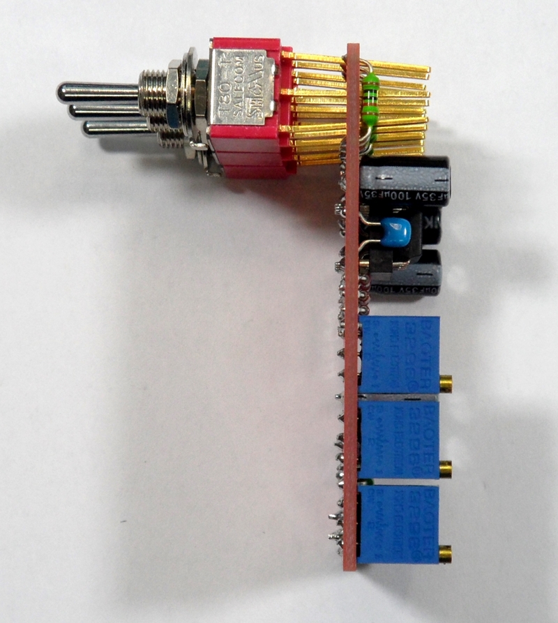
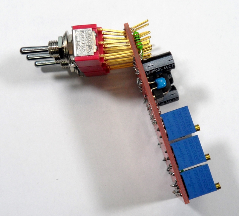
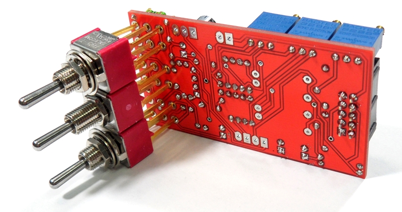
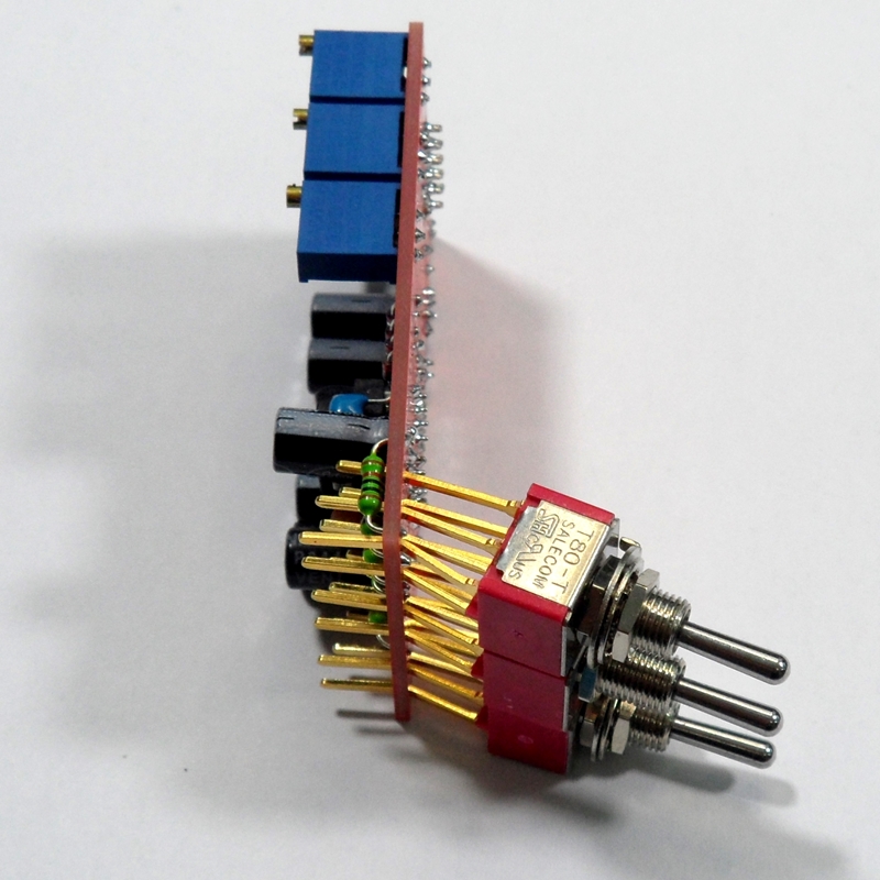
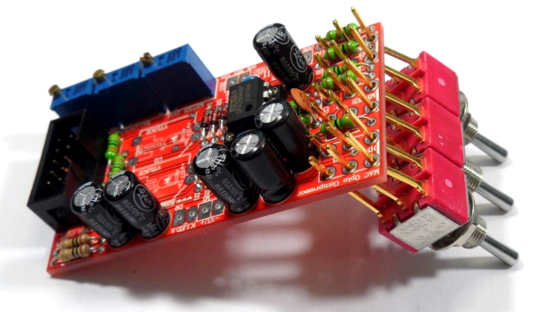
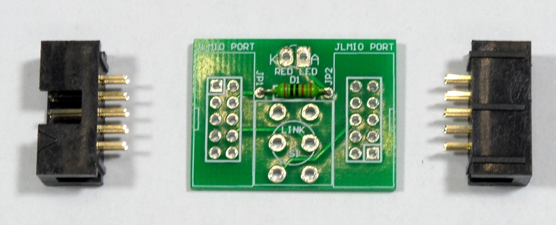
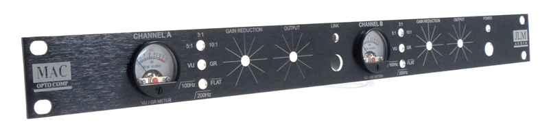
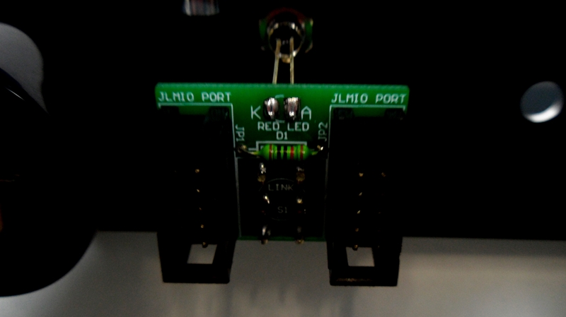
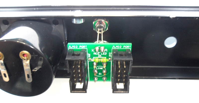
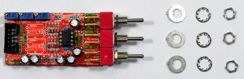
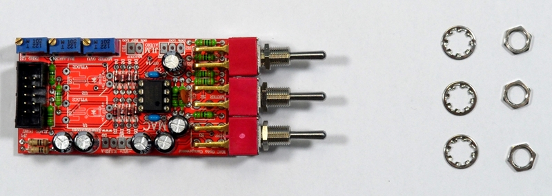
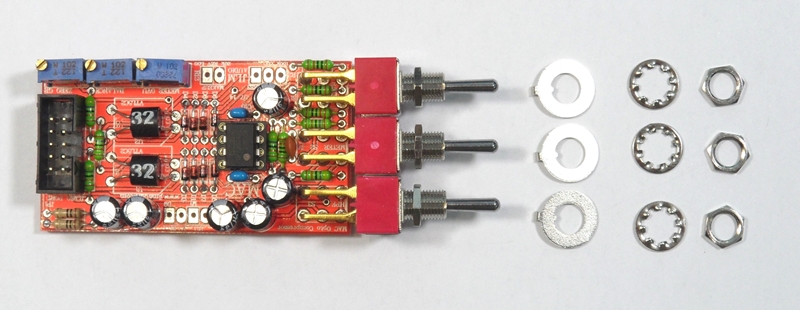
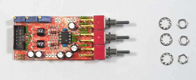
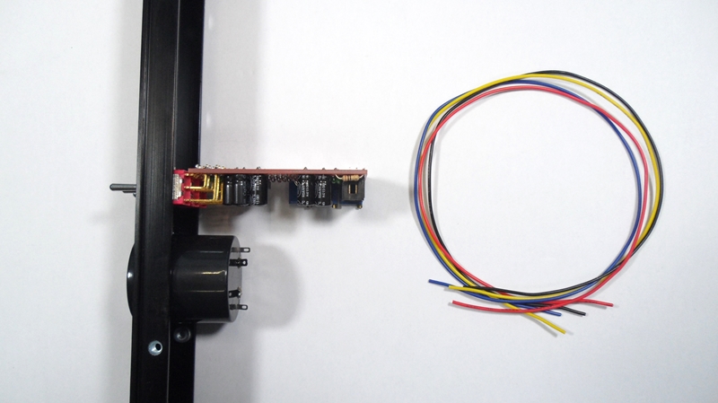
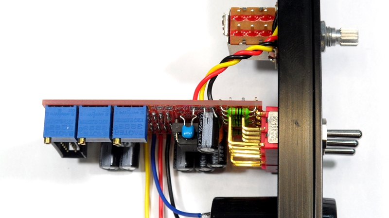
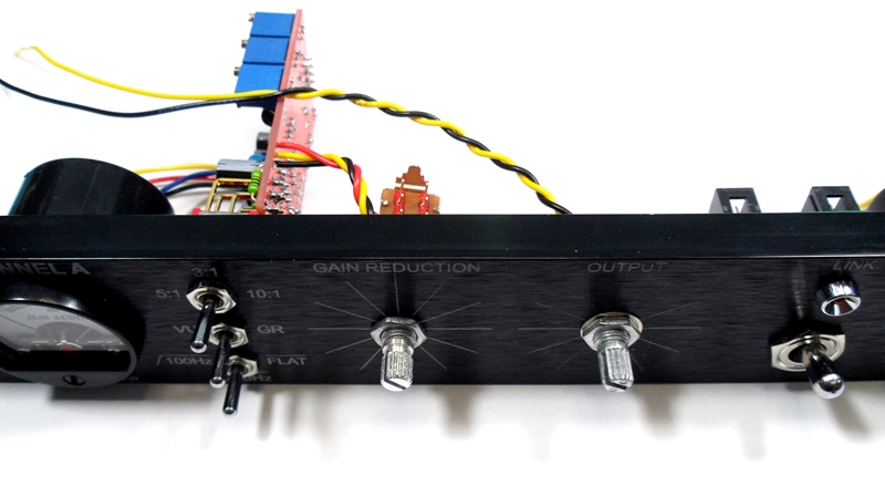
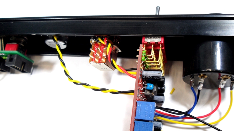
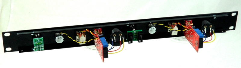
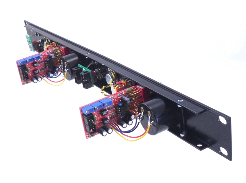
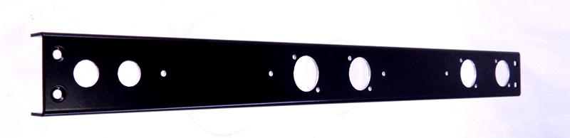
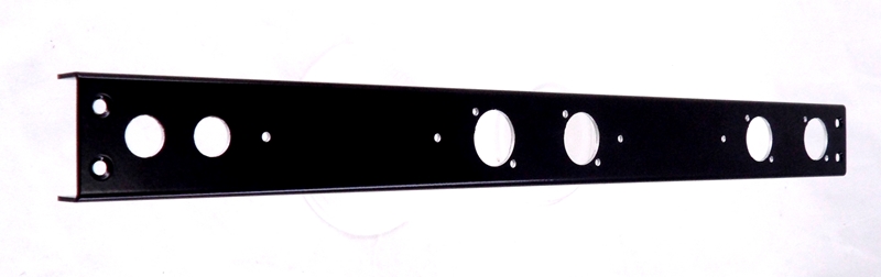
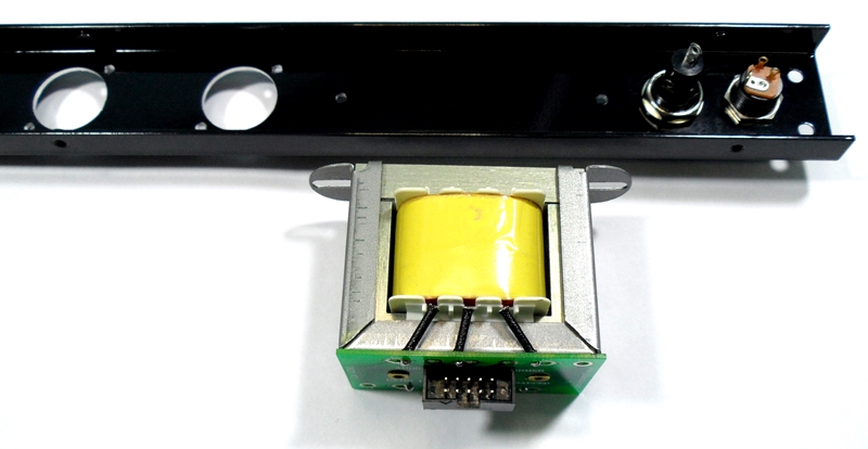
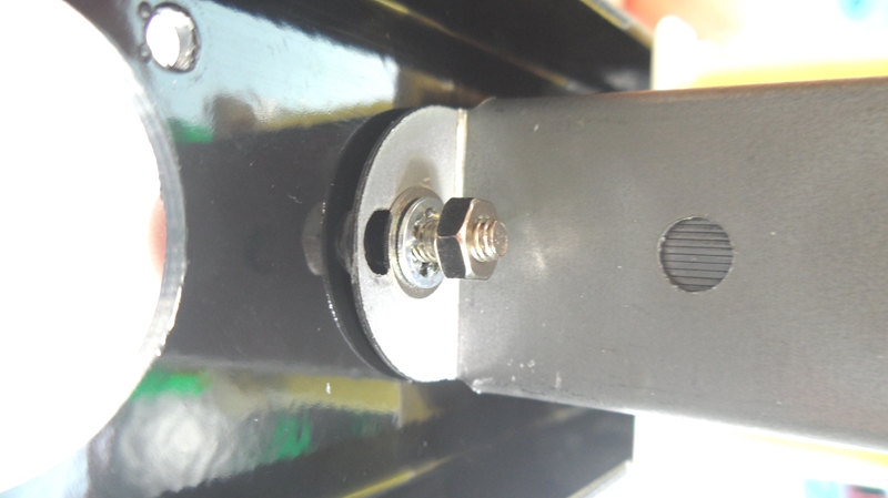
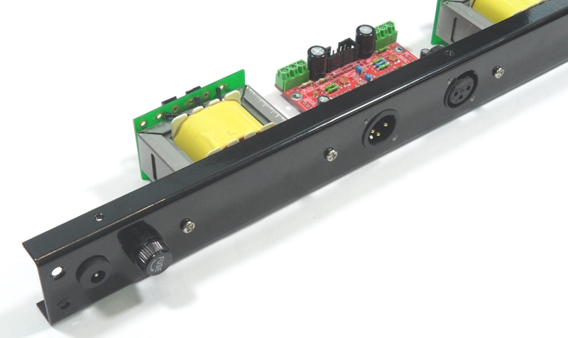
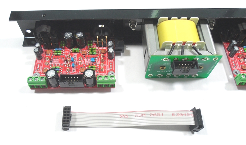
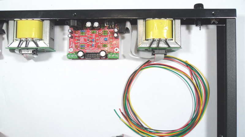
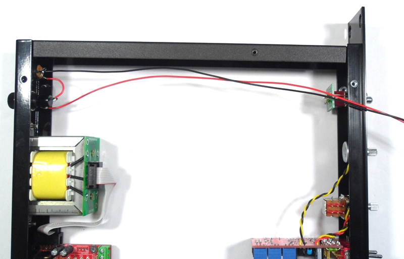
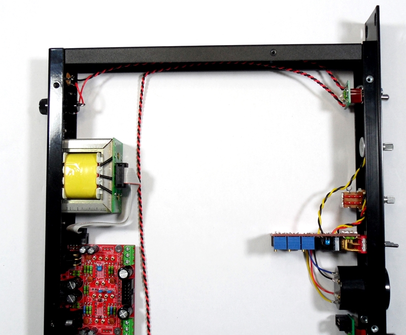
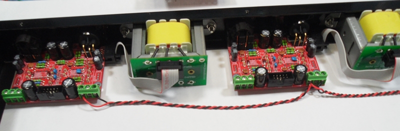
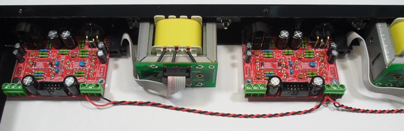
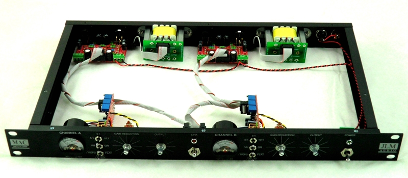
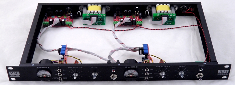
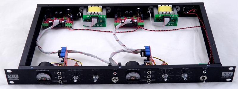
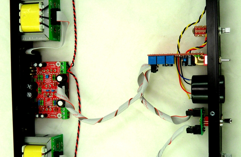
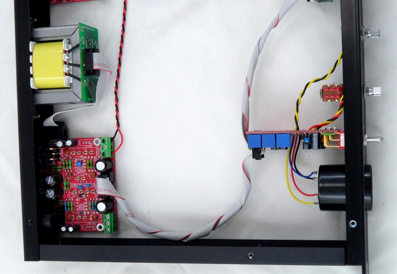
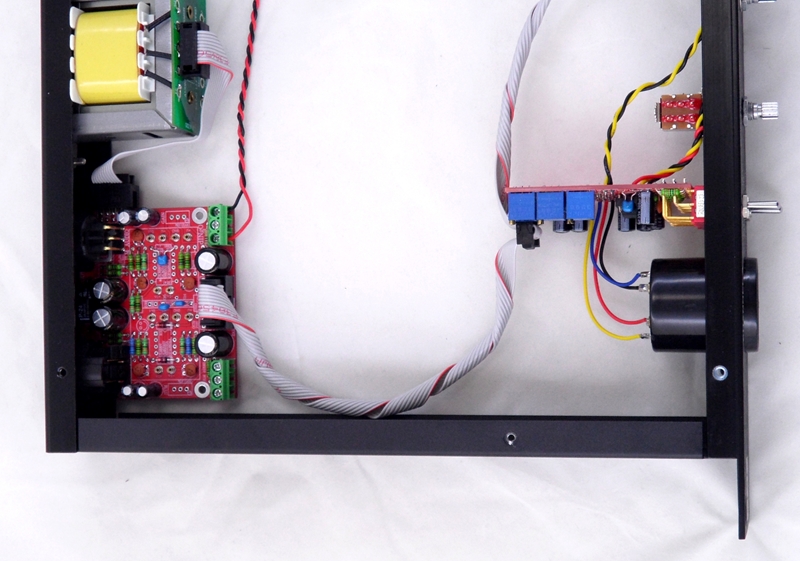
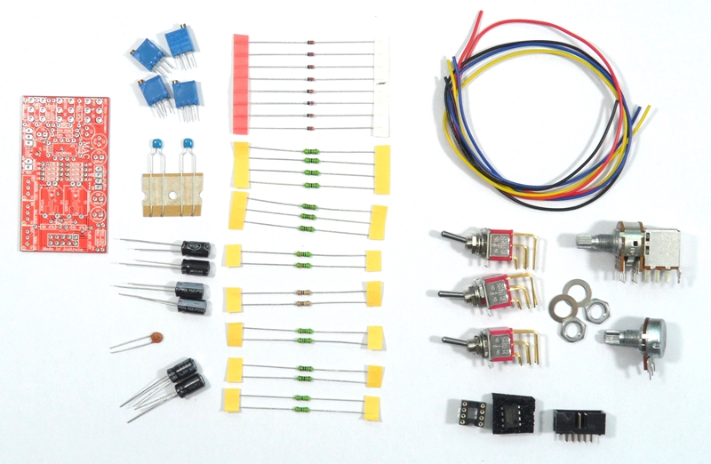
MAC rack kit uses 2 x dINgO kits
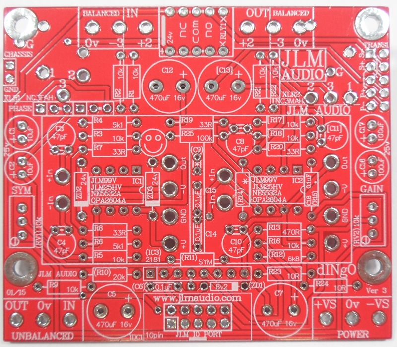
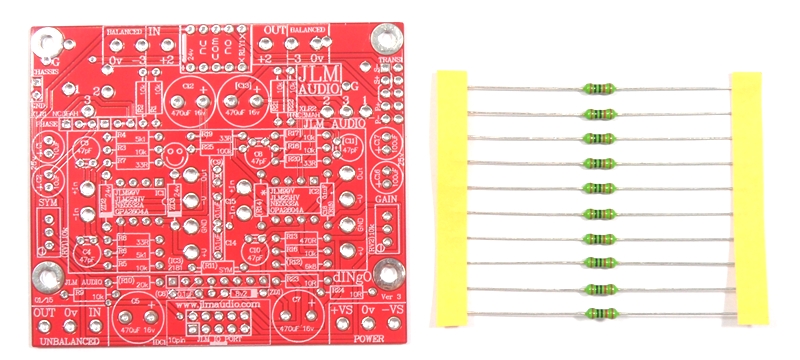
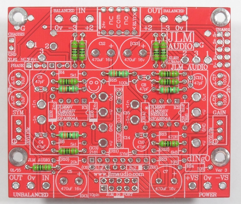
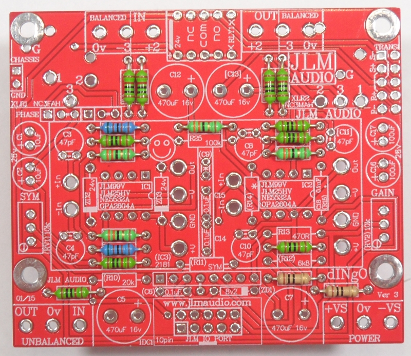
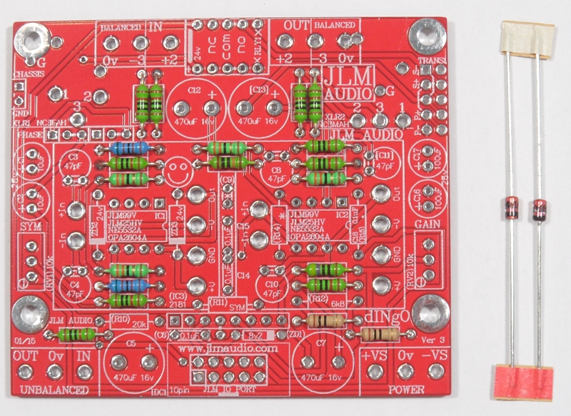
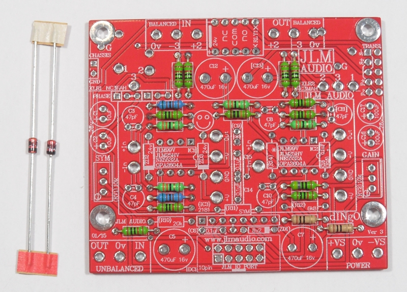
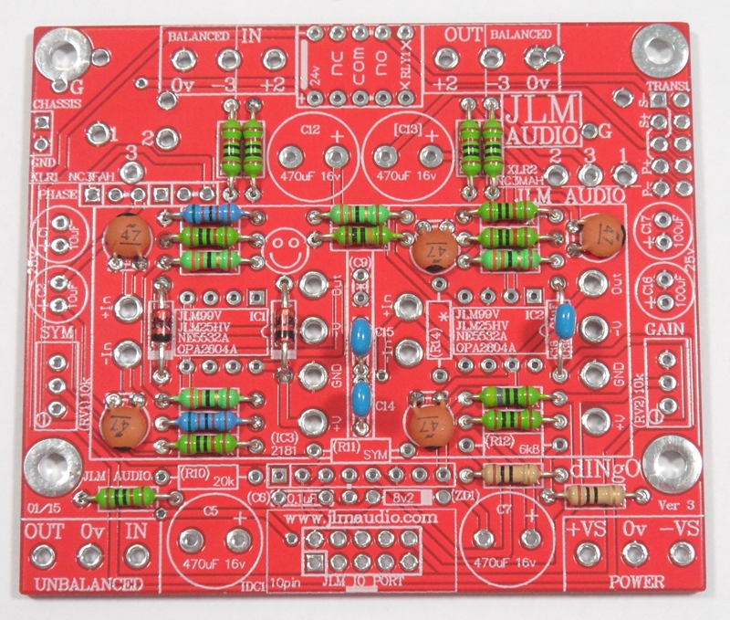
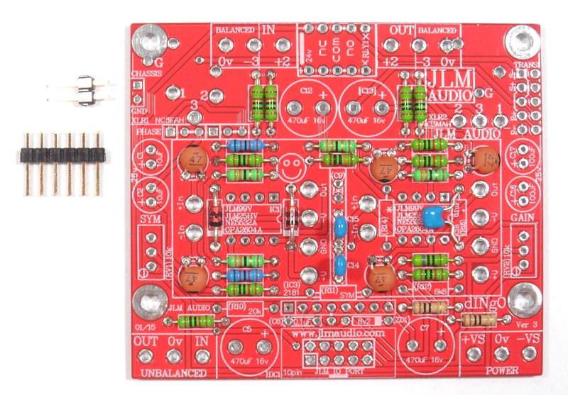
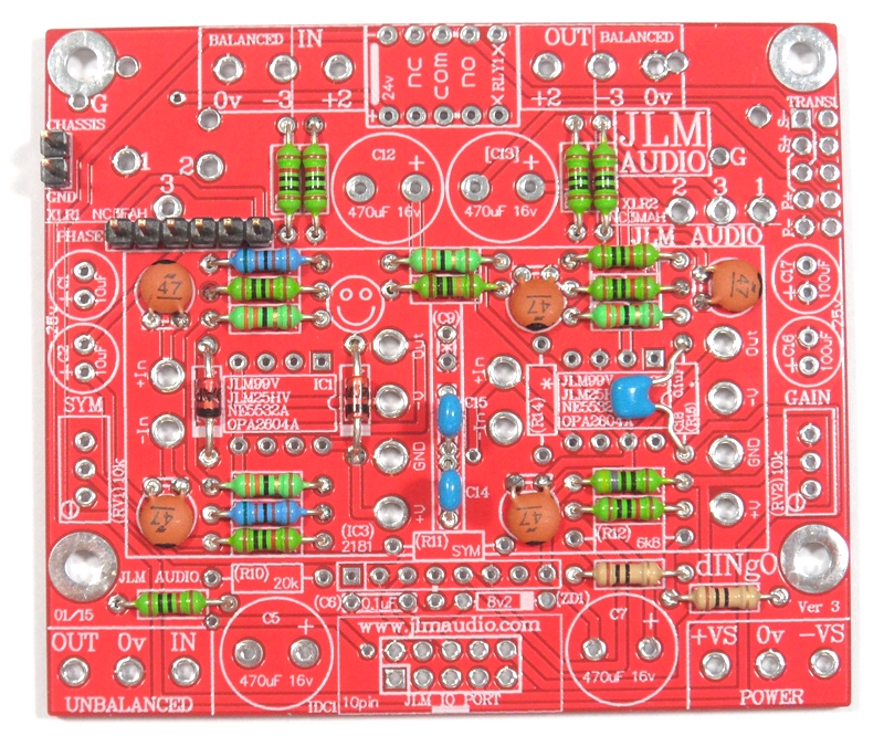
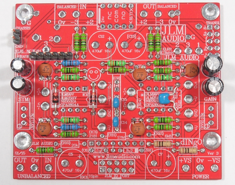
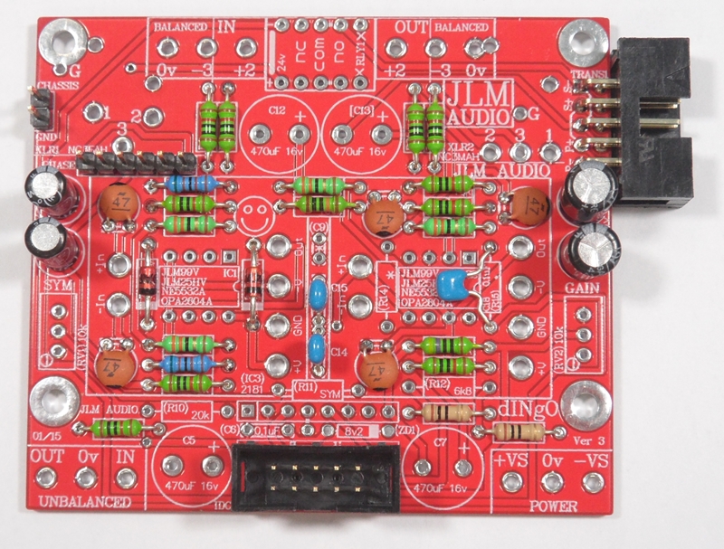
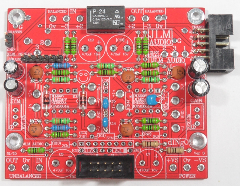
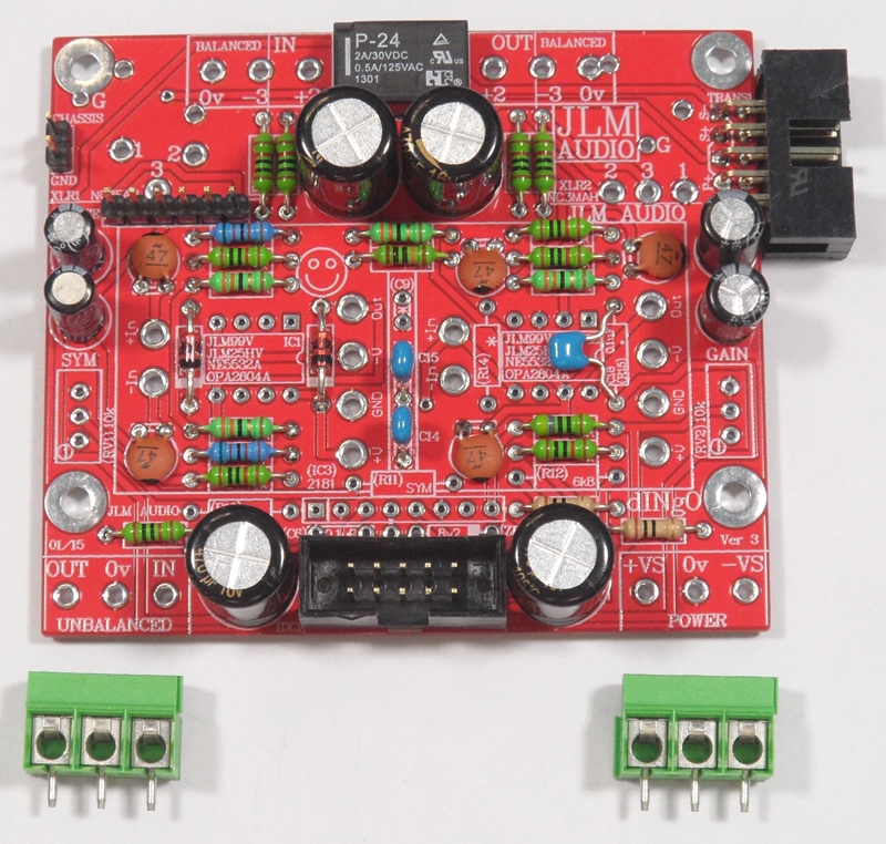
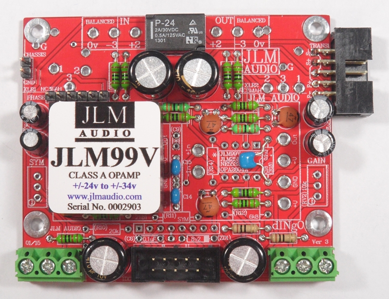
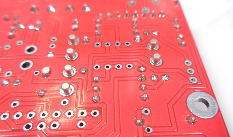
Blank dINgO PCB with full overlay shown (All parts numbers in () or [] brackets are not used with JLM99v opamps)
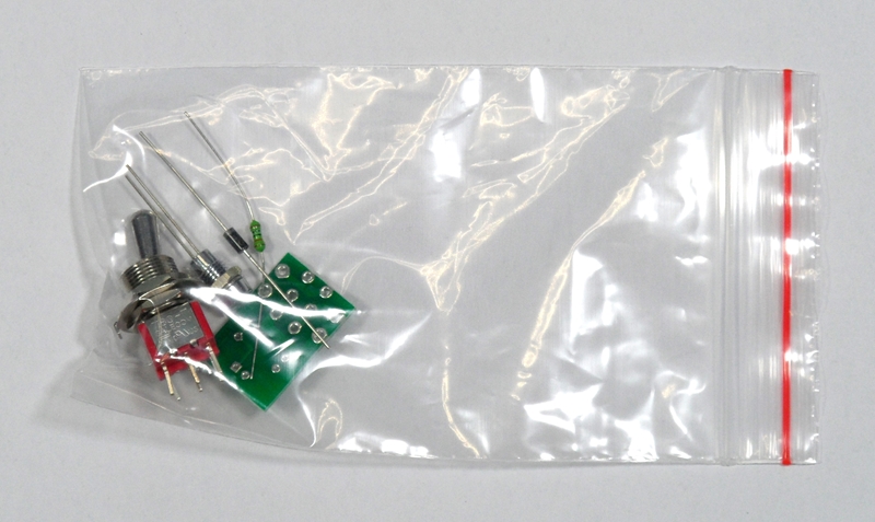
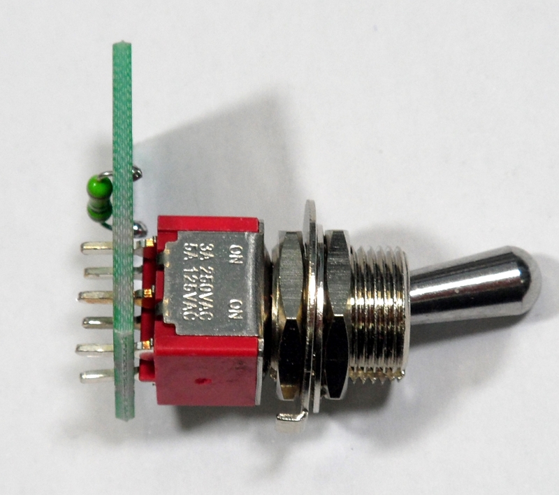
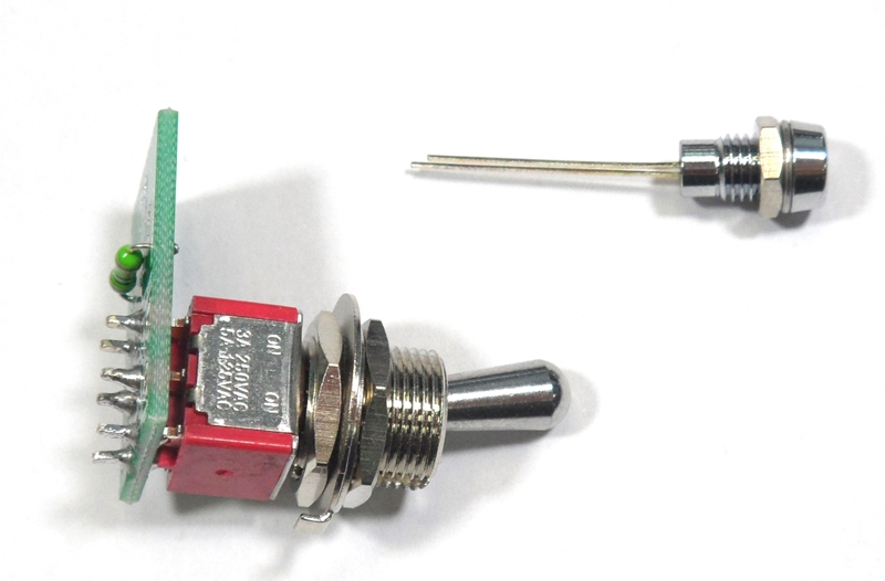
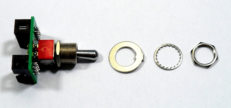
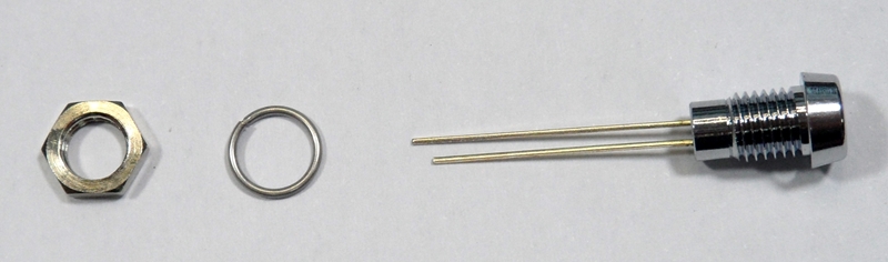
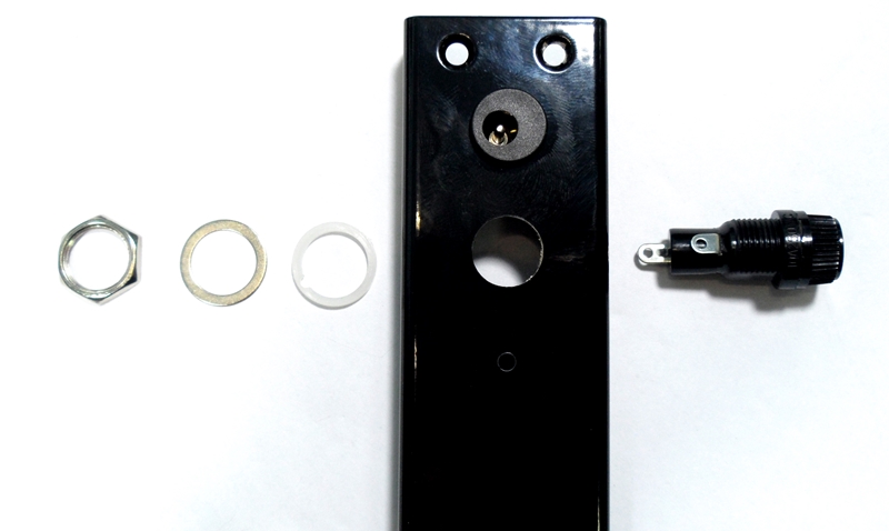
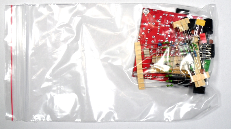
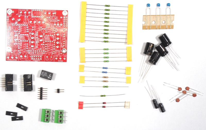
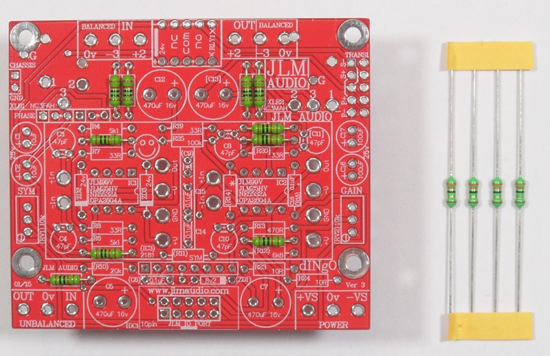
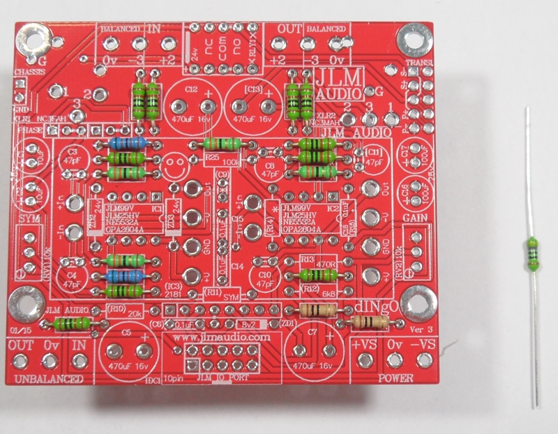
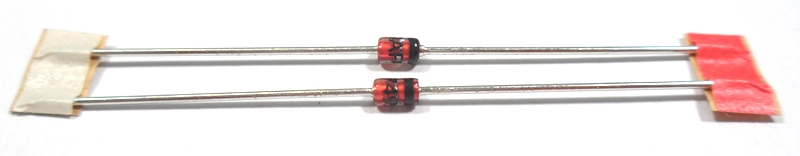
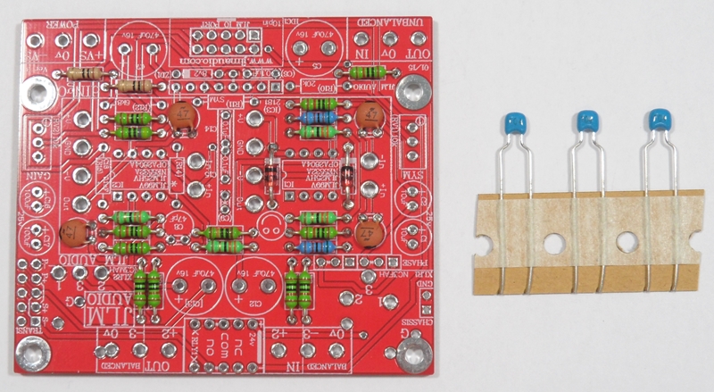
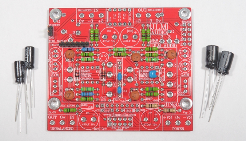
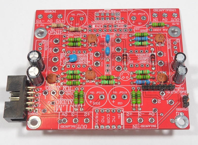
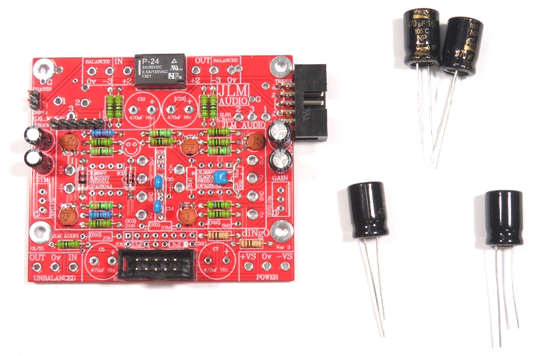
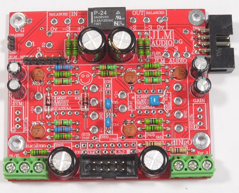
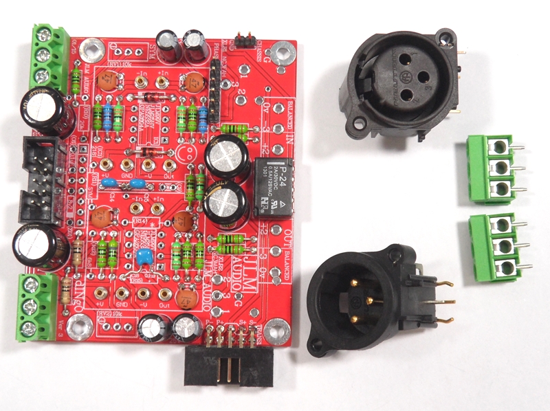
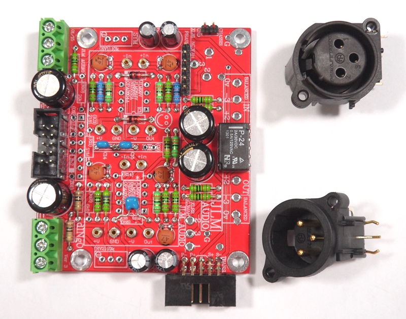
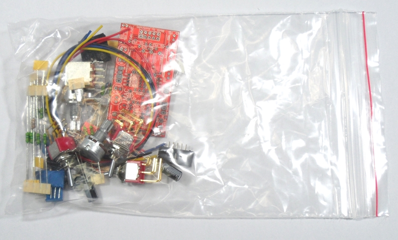
dINgO kit with all small parts shown. There will also be PCB XLR's in MAC rack kit.
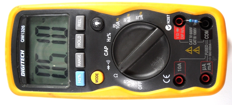
If you are not 100% with resistor colour codes use a multimeter to check values as you place the resistors
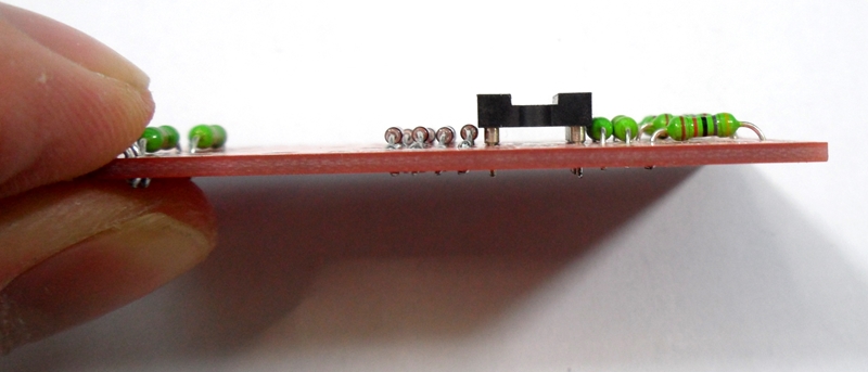
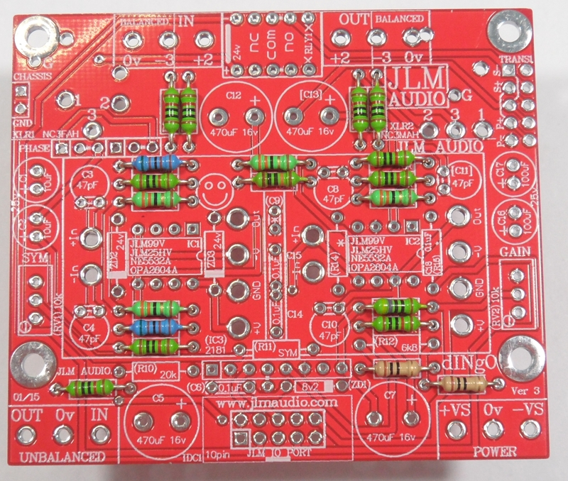
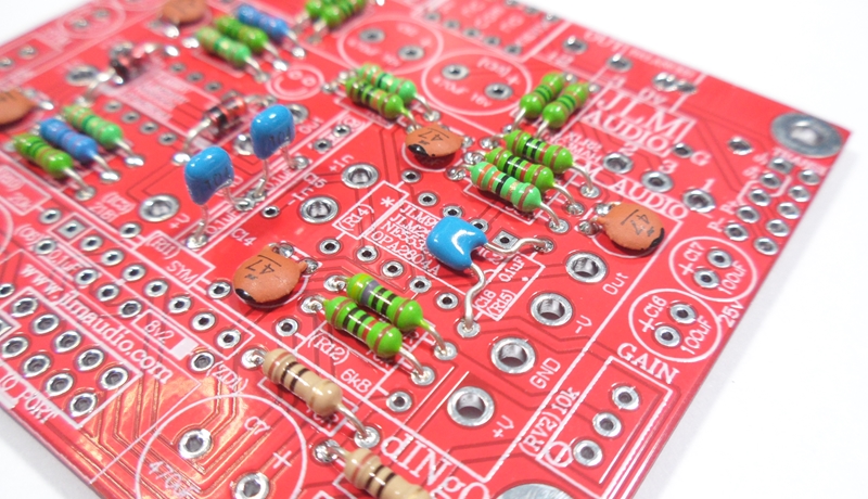
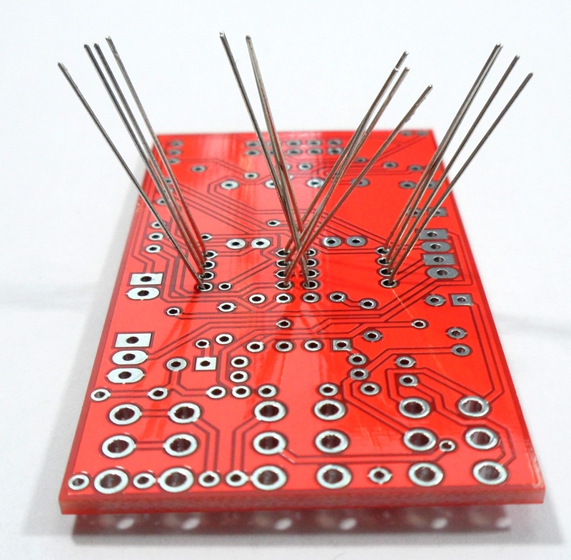
Fit all resistors at once bending the legs sightly outwards to hold them in place. This helps to make sure no resistors are put in the wrong position.
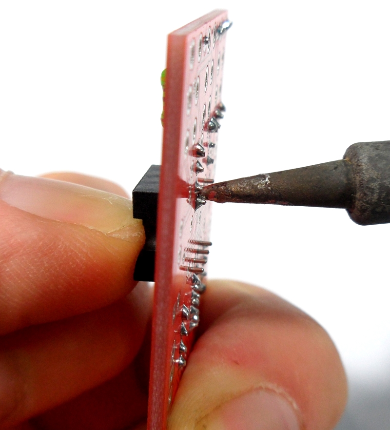
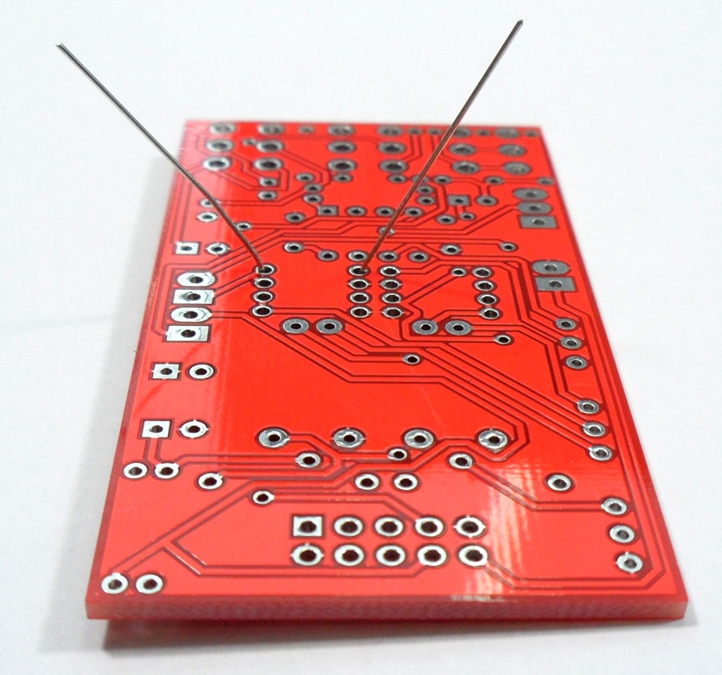
Start with fitting of the 10k resistors into the PCB and bend the legs slightly outwards so they do not fall out when PCB is turned over.
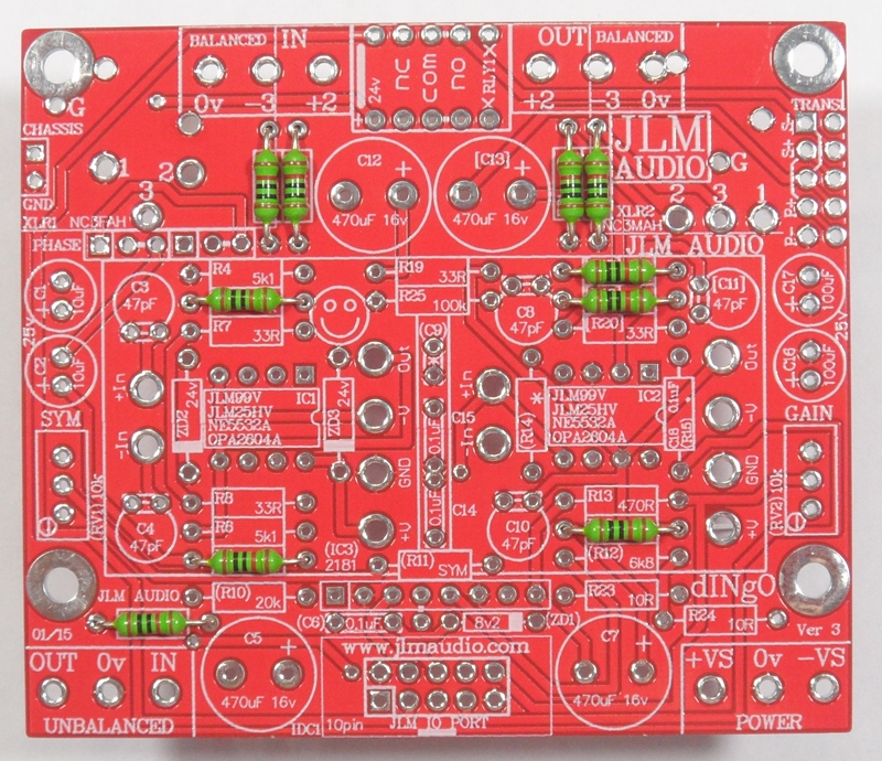
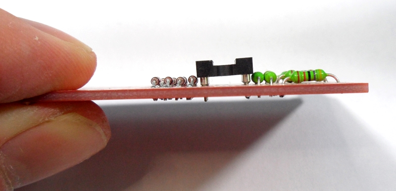
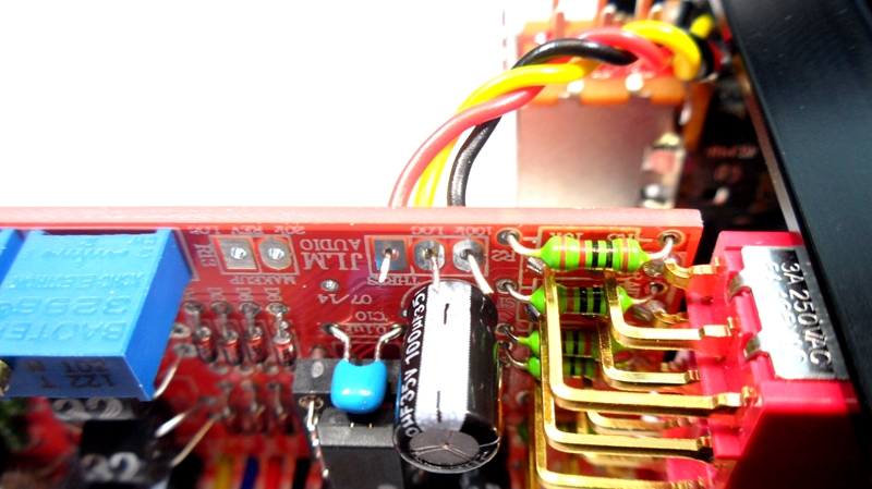
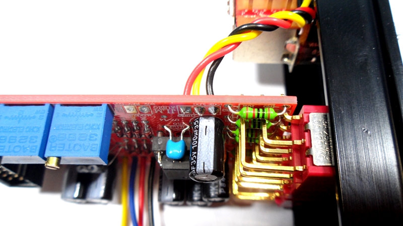
Fitting of the 33R resistors
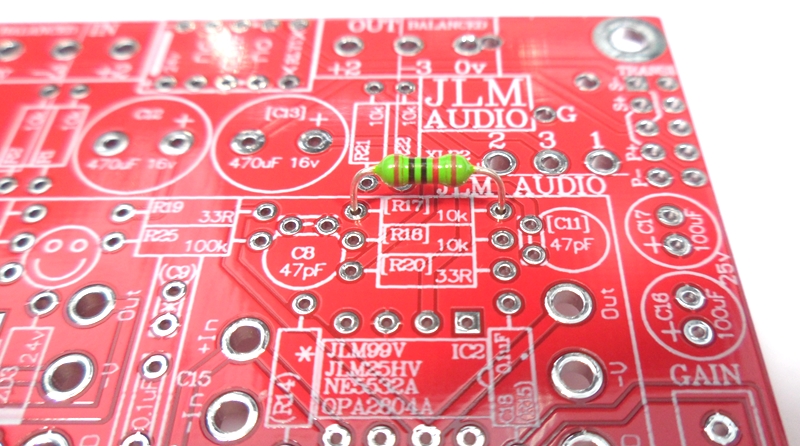
Fitting of the 5k1 resistors

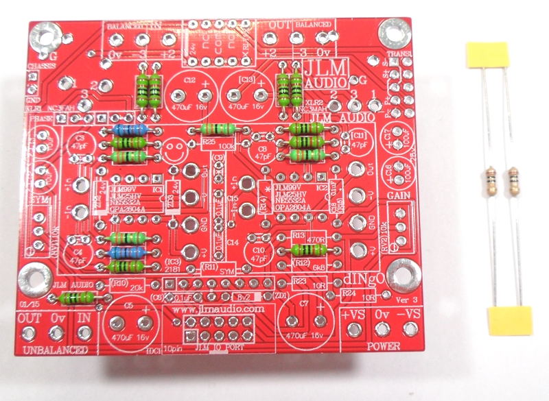
Fitting of the 10R resistors
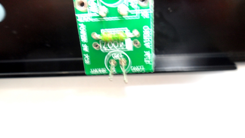
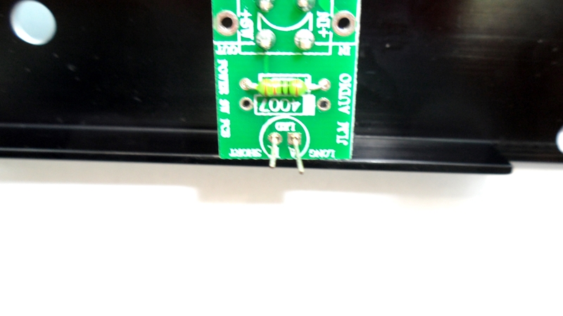
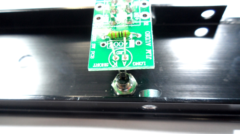
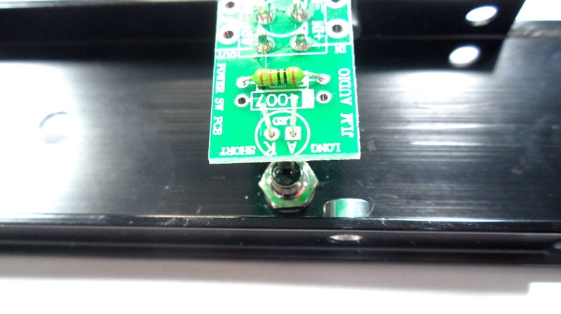
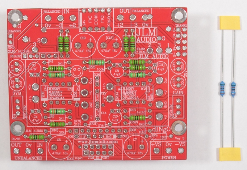
Fitting of the 470R resistor
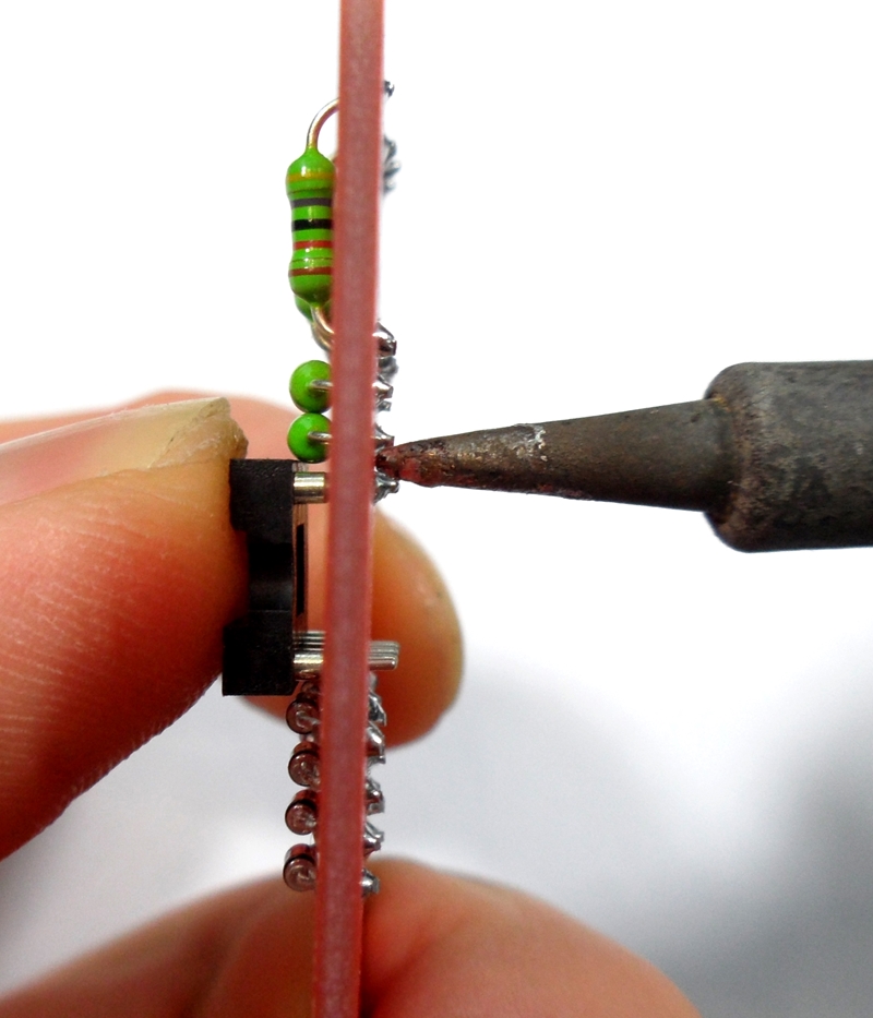
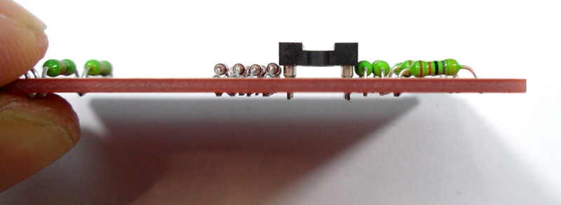
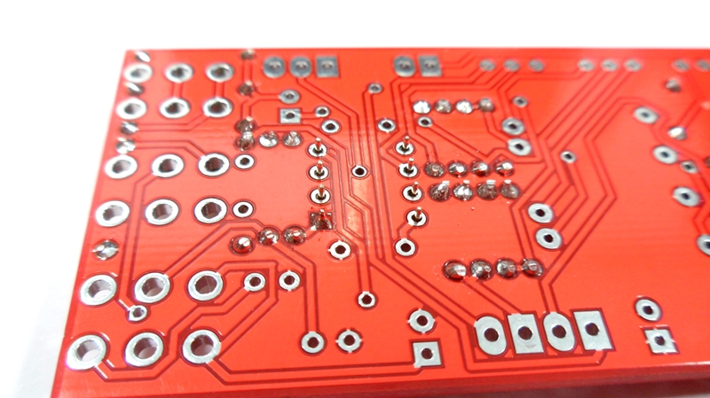
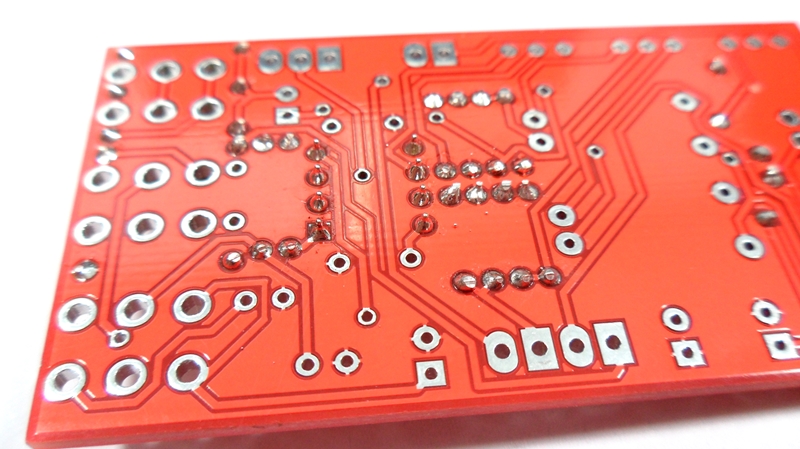
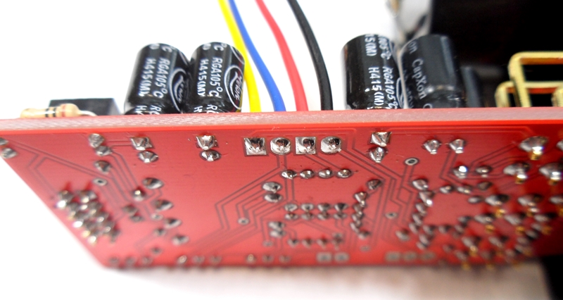
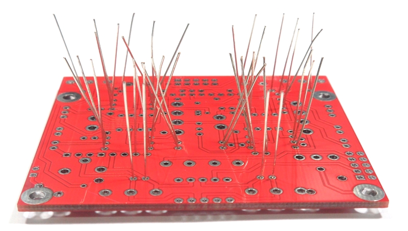
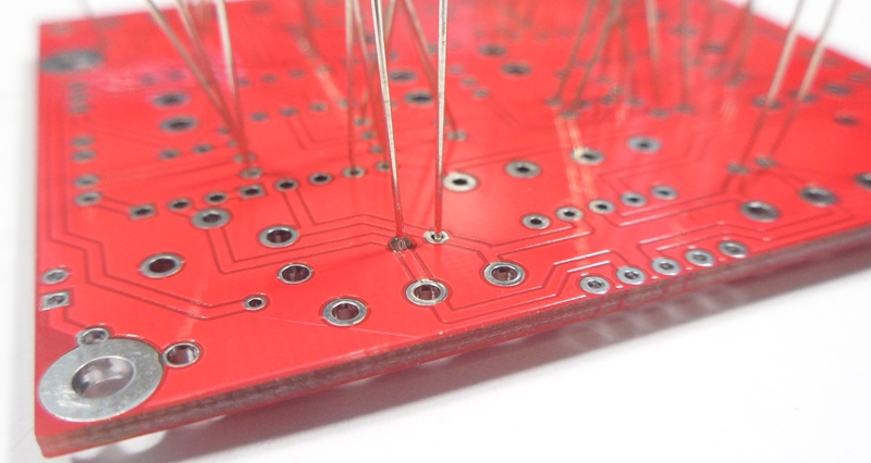
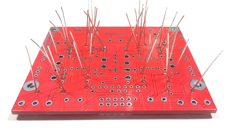
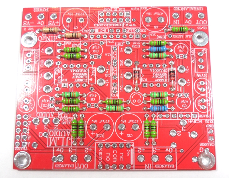
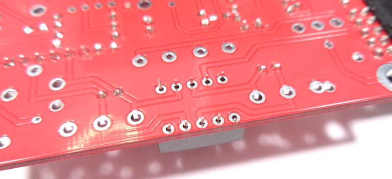
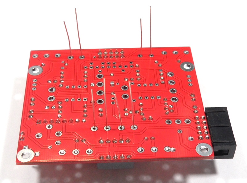
Turn over PCB on flat surface and solder and trim all resistors legs
Fit the two 24v zener diodes with stripes lined up with stripe on PCB and solder and trim legs

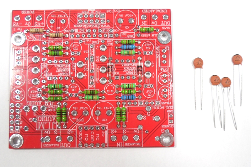
Fit the 4 x 47pF ceramic caps folded flat to the PCB and solder and trim legs

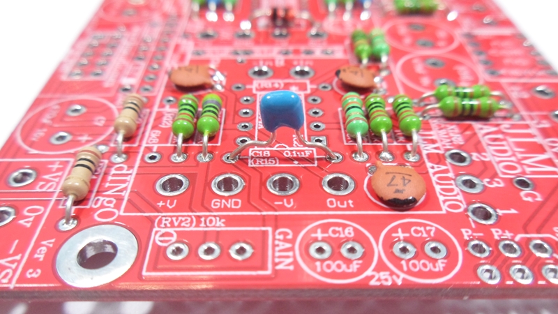
Fit the 3 x 100nF mono caps with one folded flat to the PCB and solder and trim legs
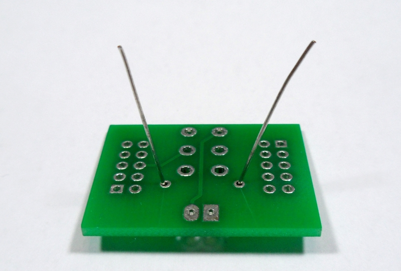
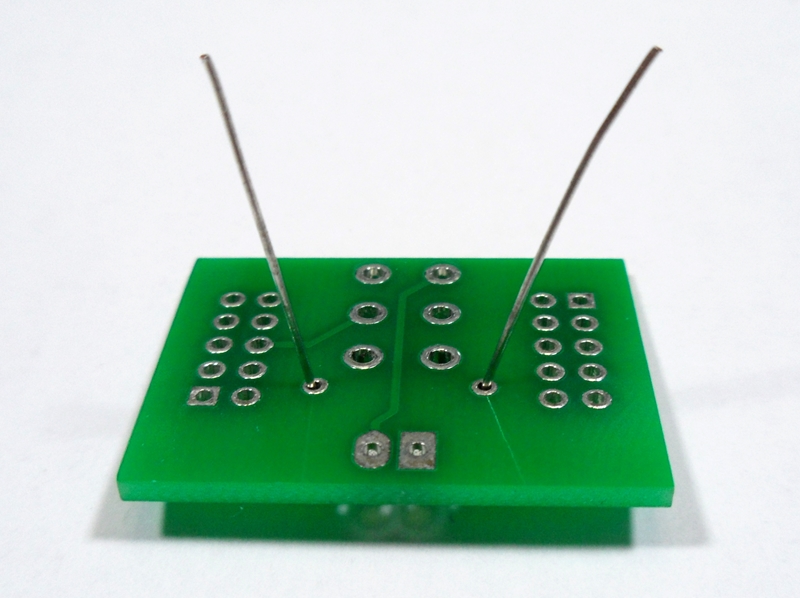
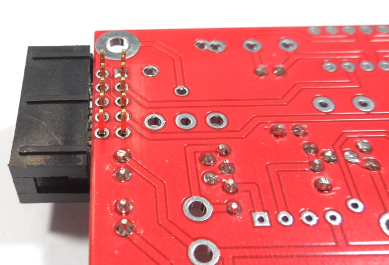
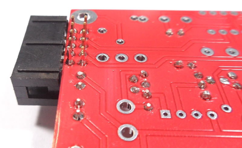
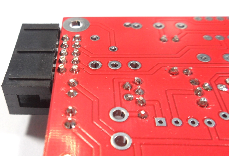
Fit the 2 x gold pin sets to the PCB and solder. Best to solder one pin on each and check if they are sitting straight before soldering all pins.

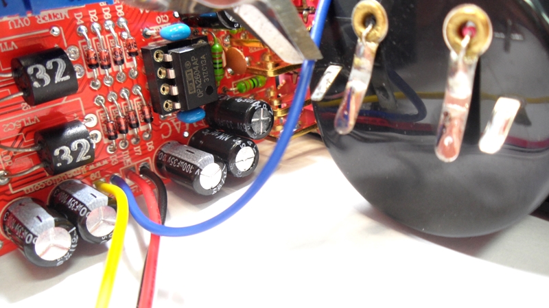
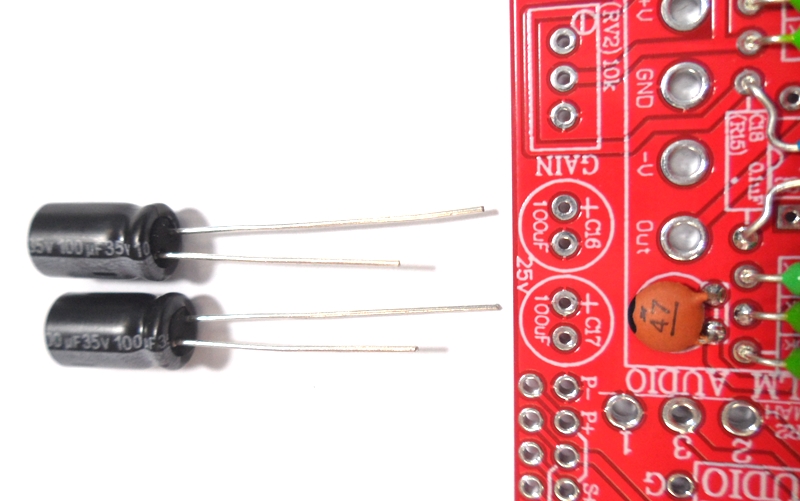
Fit the 2 x 10uF & 2 x 100uF electro caps the check way around to the PCB and solder and trim legs. (+leg is the long leg of the cap)
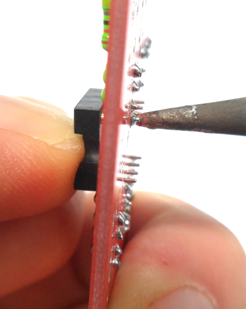
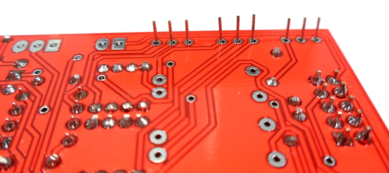
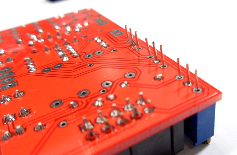
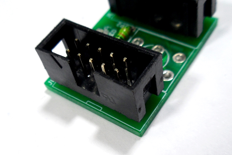
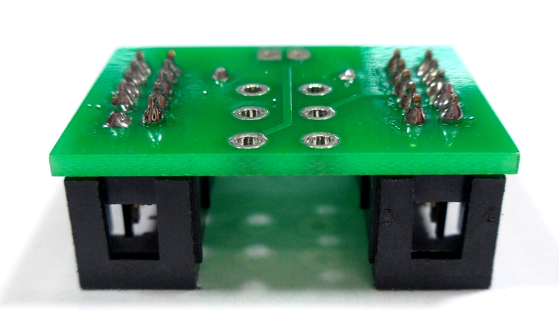
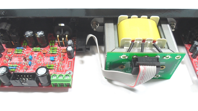
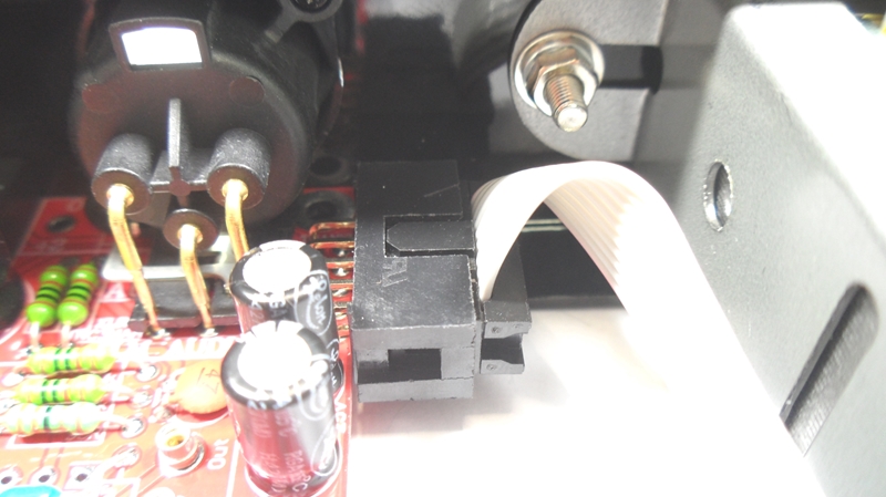
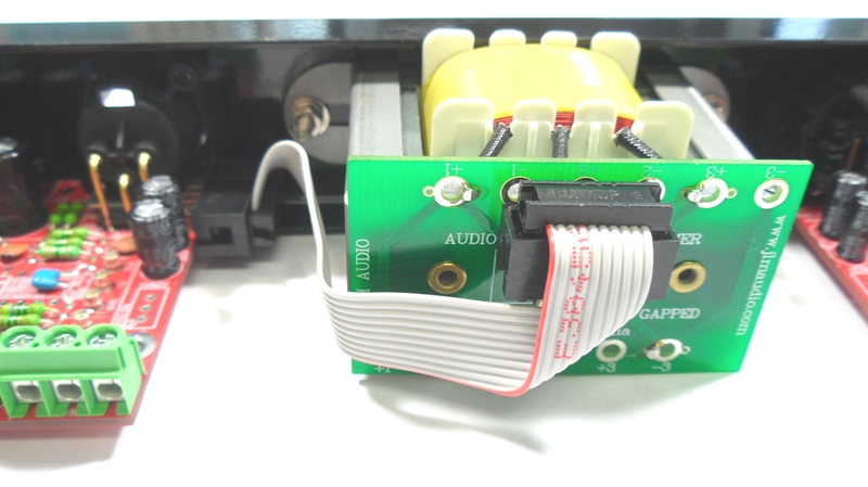
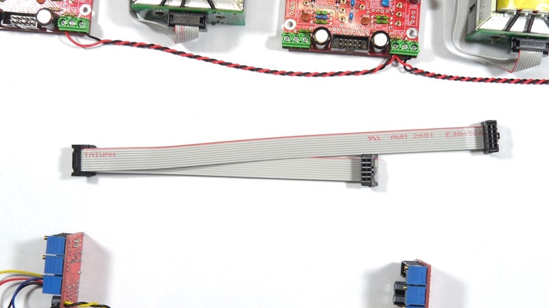
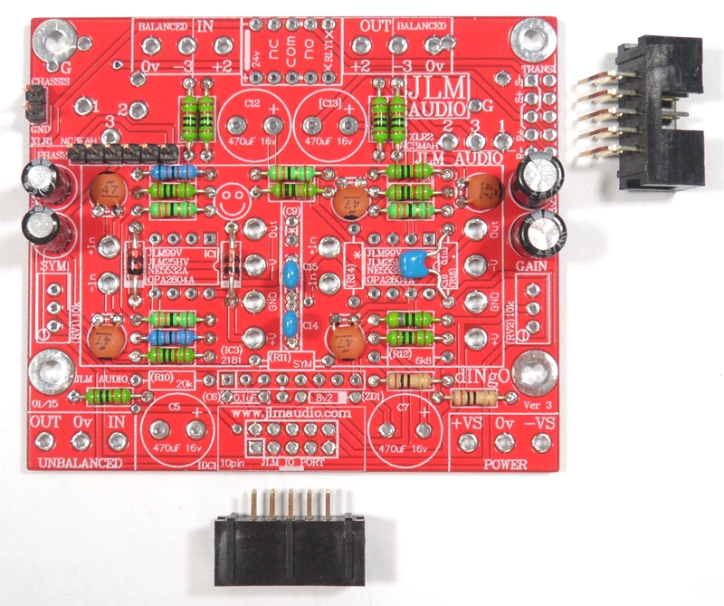
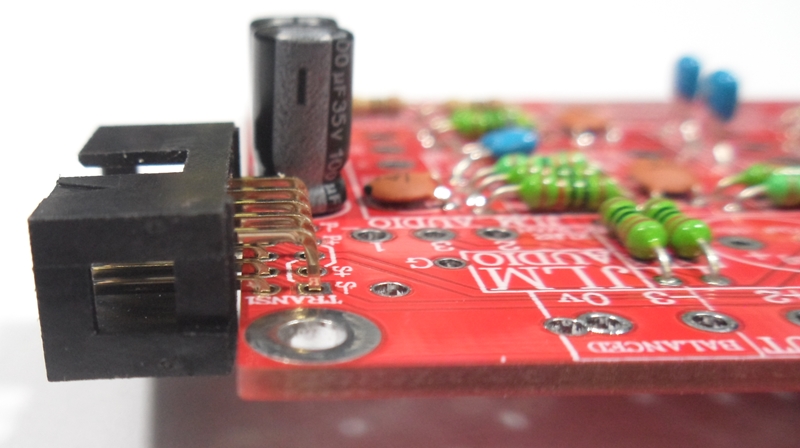
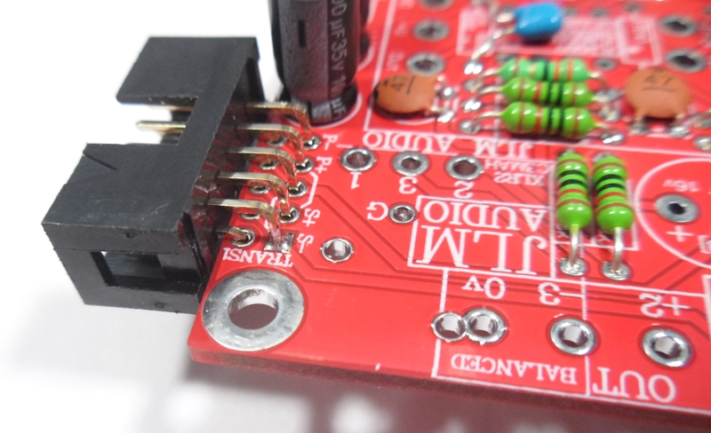
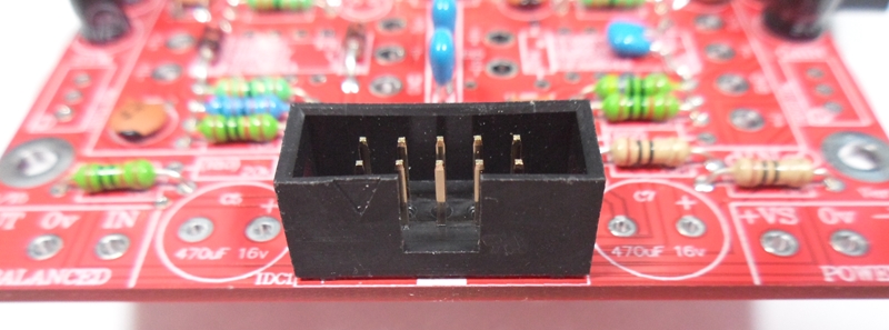
Fit 2 x 10pin IDC headers to the PCB and solder and trim legs.

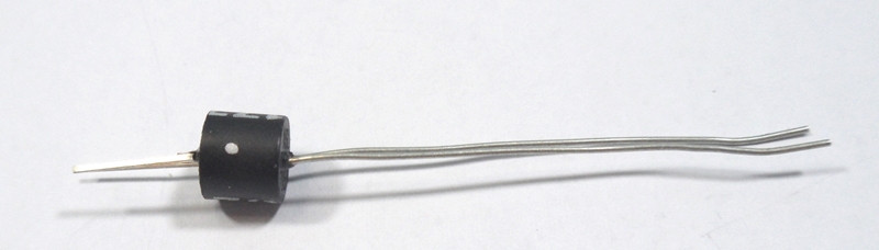
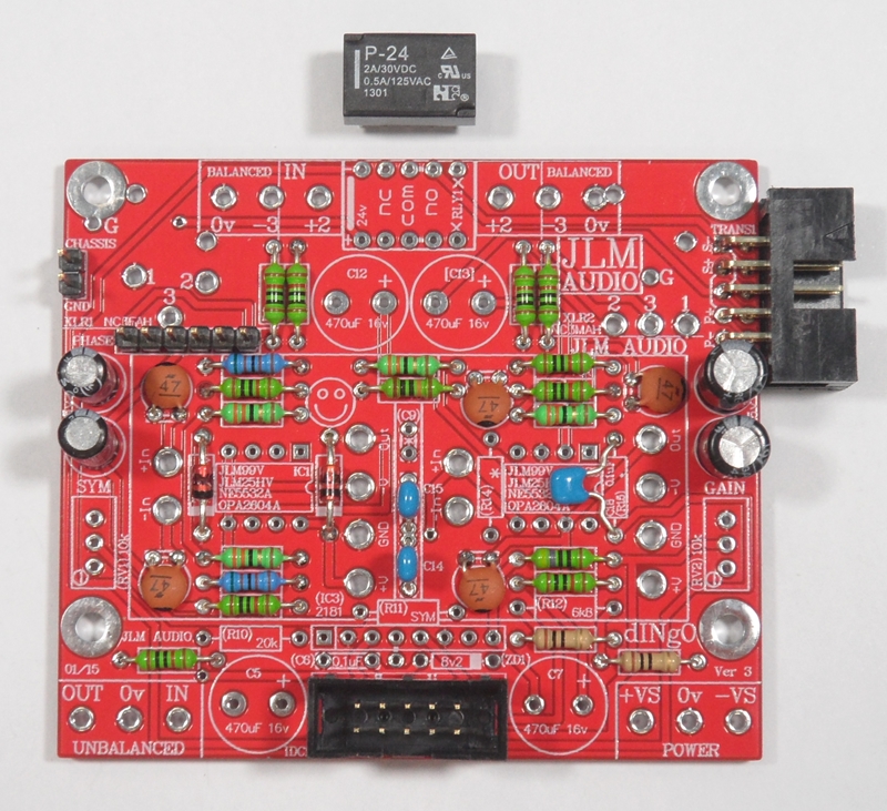
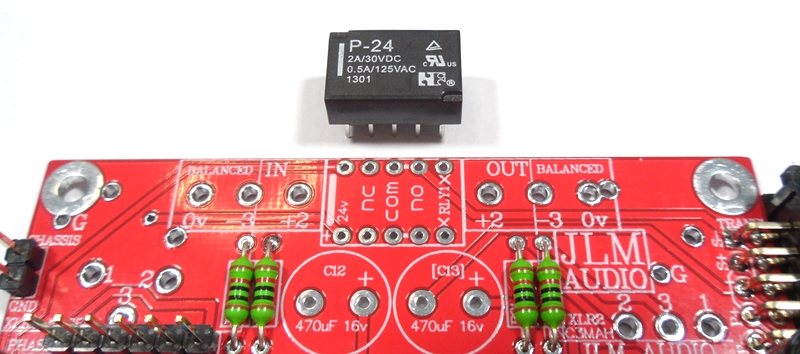
Fit 24v relay to the PCB and solder and trim legs. Make sure stripe on relay matches stripe on PCB
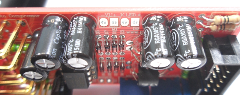
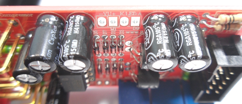
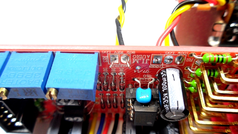
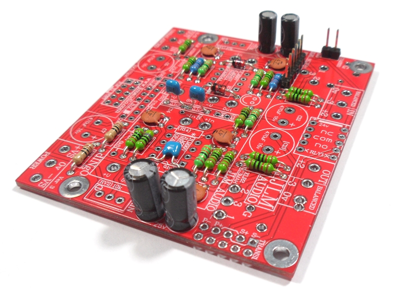
Fit 4 x 470uF 16v Non Polar electro caps to the PCB and solder and trim legs. These are Non Polar so can be fitted either way around.
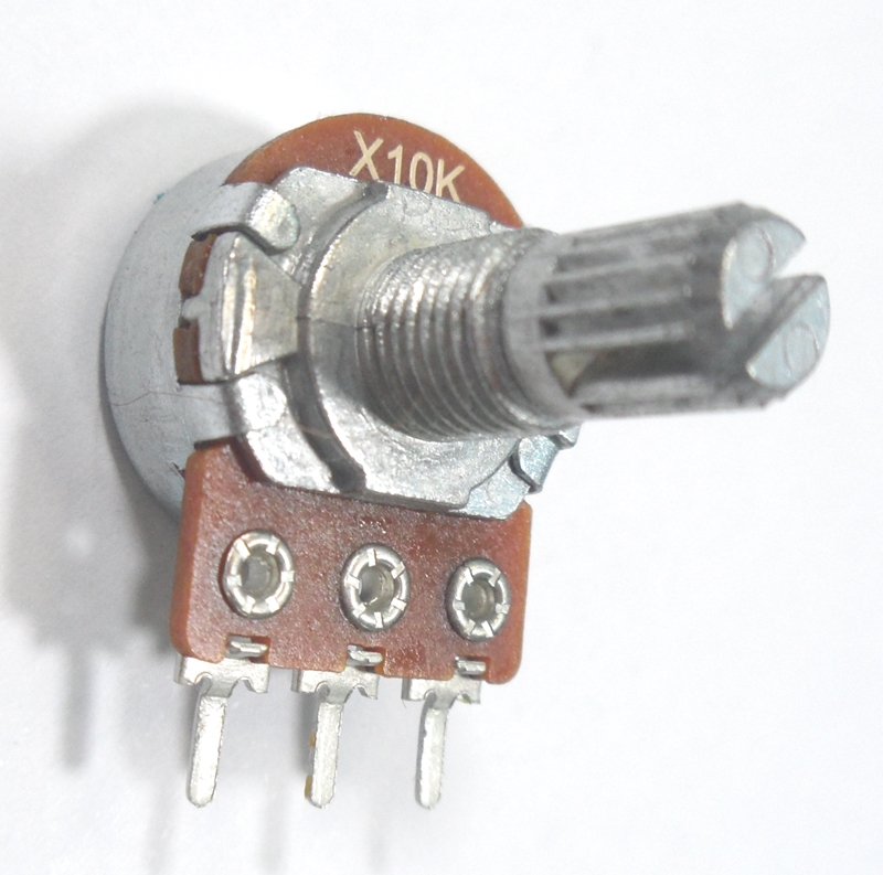
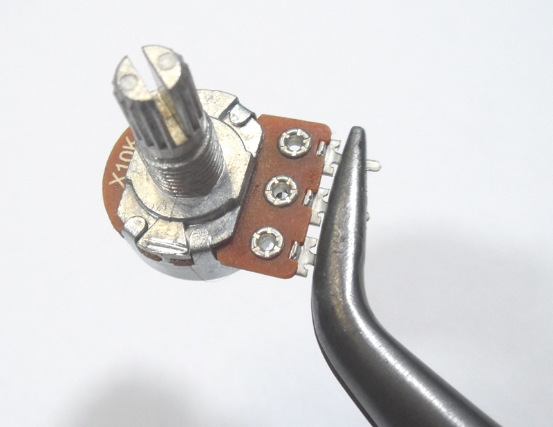
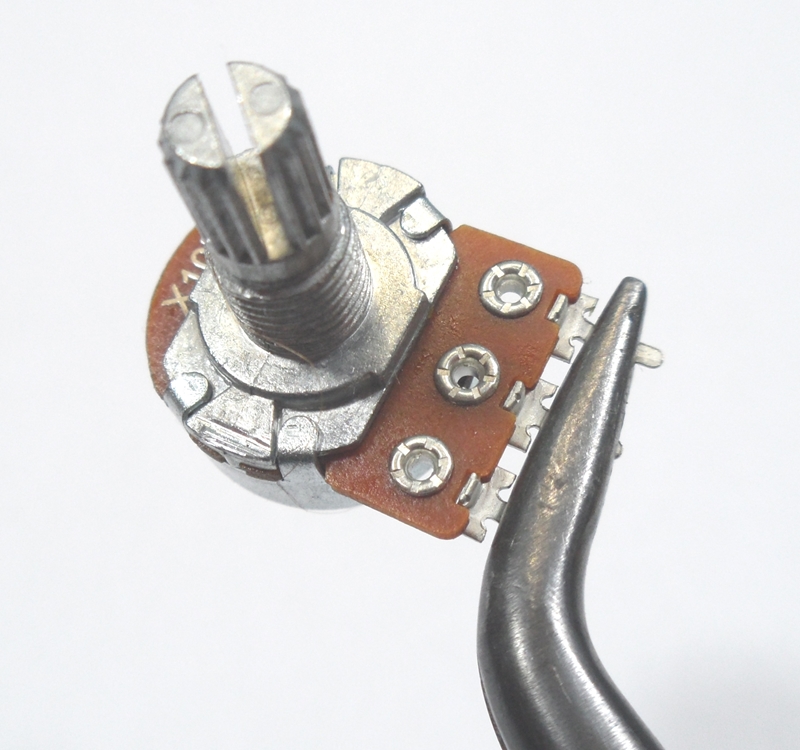
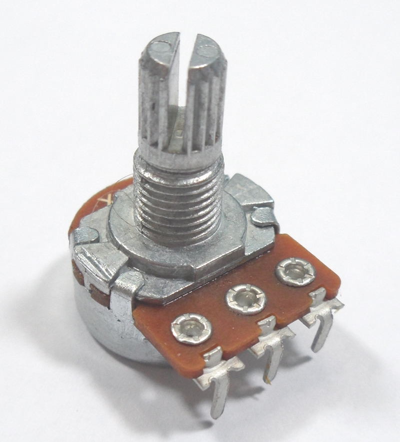
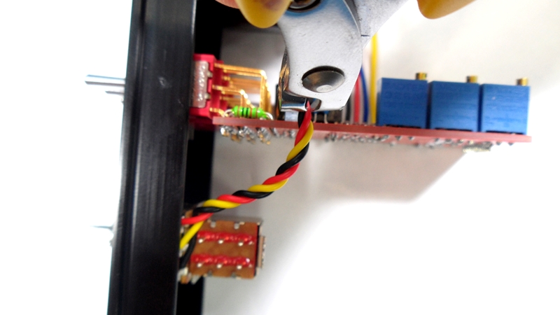
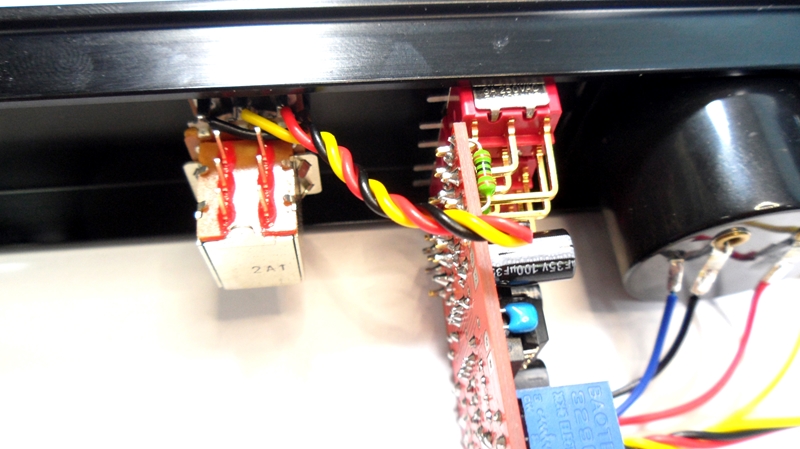
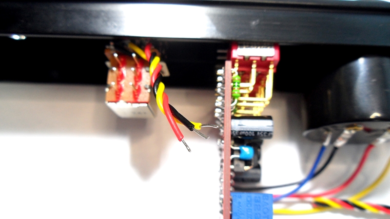
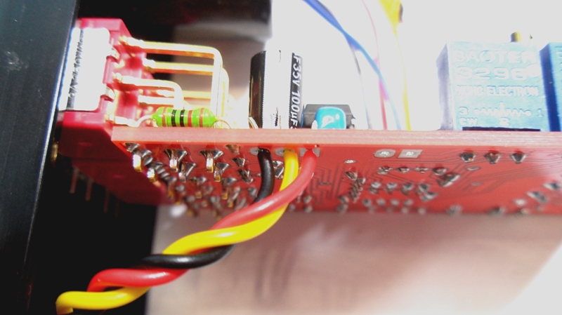
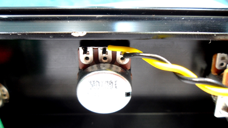
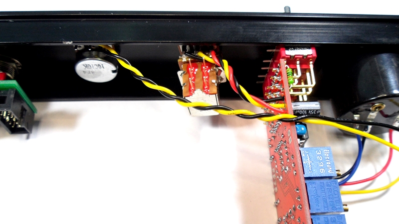
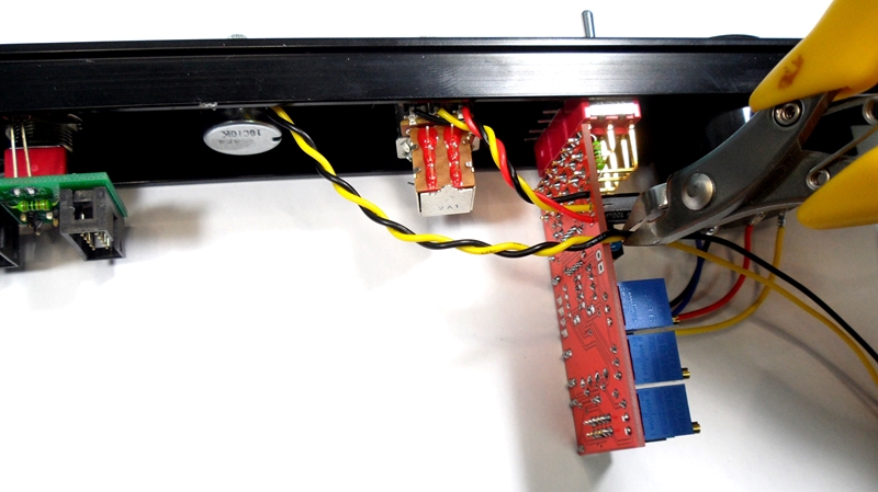
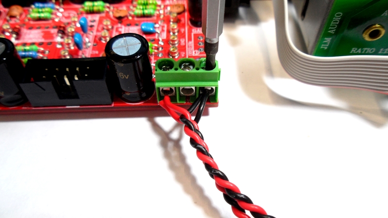
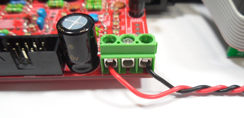
Fit 2 x 3way terminal block to the PCB and solder and trim legs.
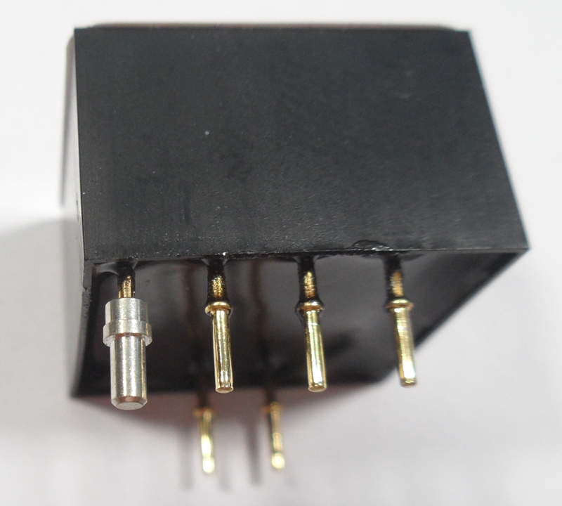
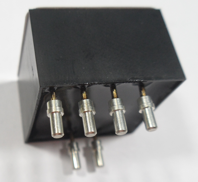
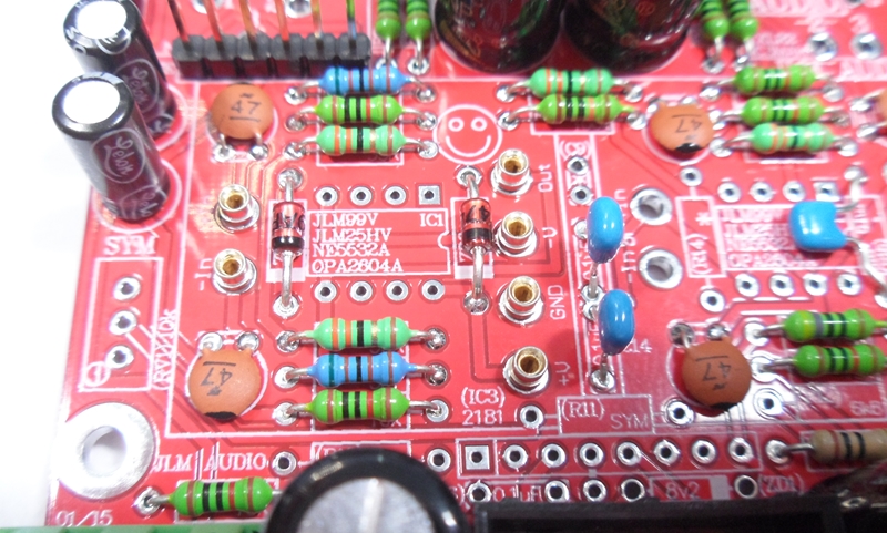
Fit 12 pins for the 2 x JLM99v opamps to the PCB and solder and trim legs.

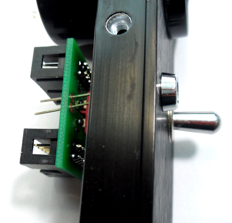
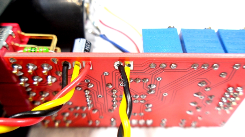
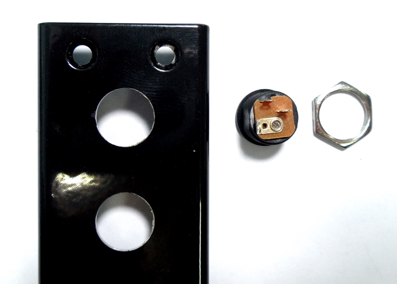
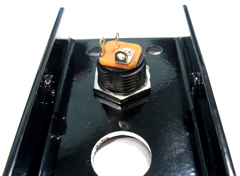
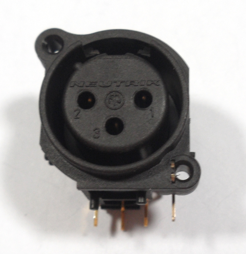
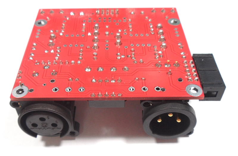
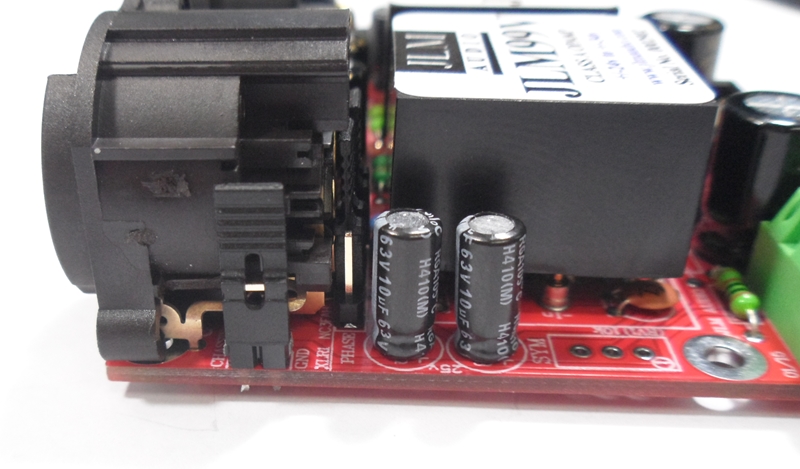
Fit Male and Female XLR to the PCB and solder and trim legs. There maybe left over 3 way terminal blocks in the kit.
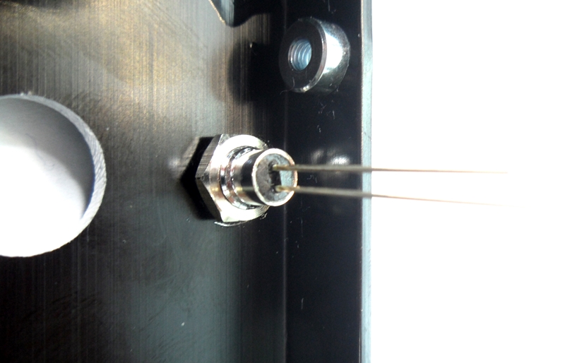
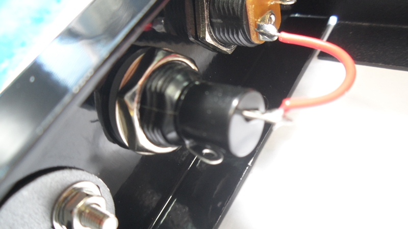
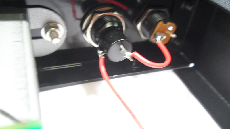
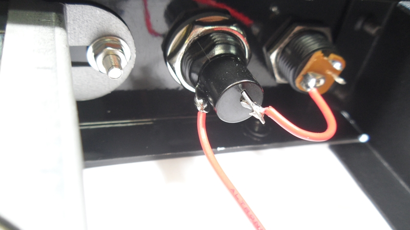
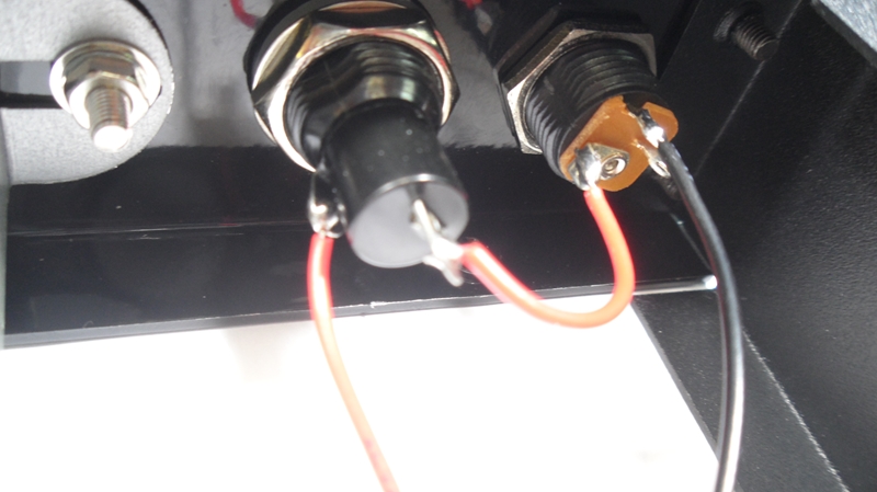
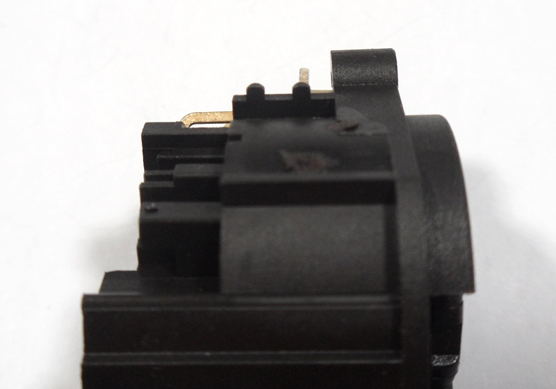
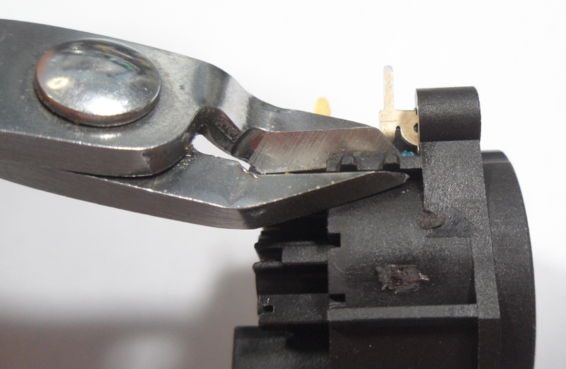
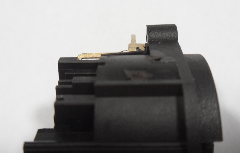
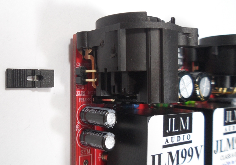
Trim side of Female XLR with sidecutters as shown
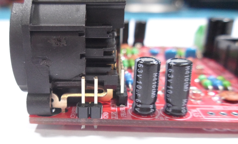
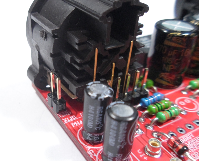
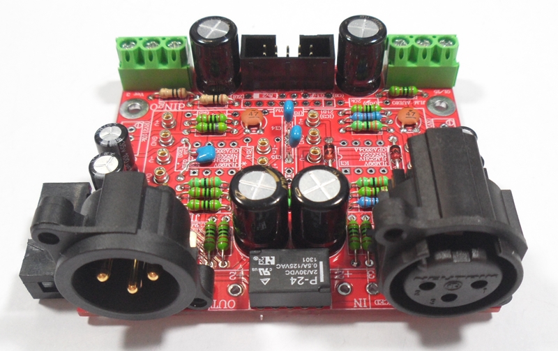
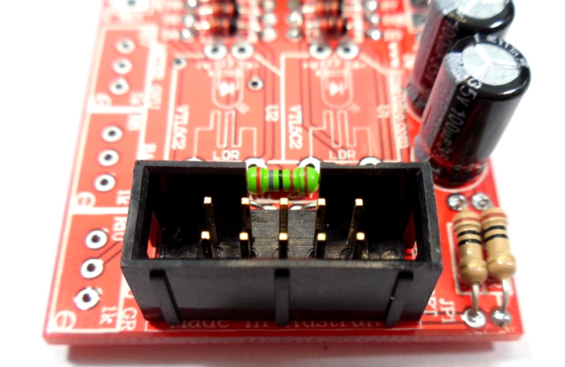
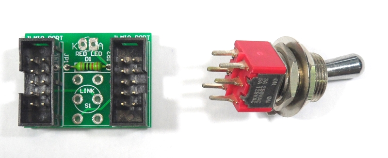
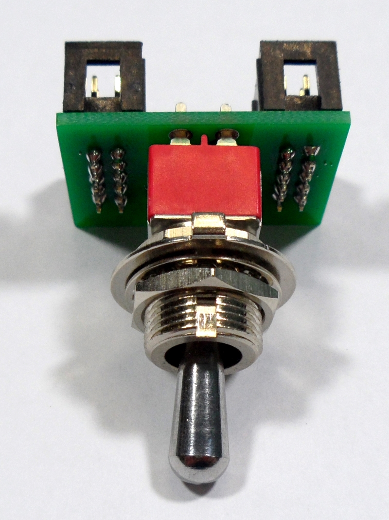
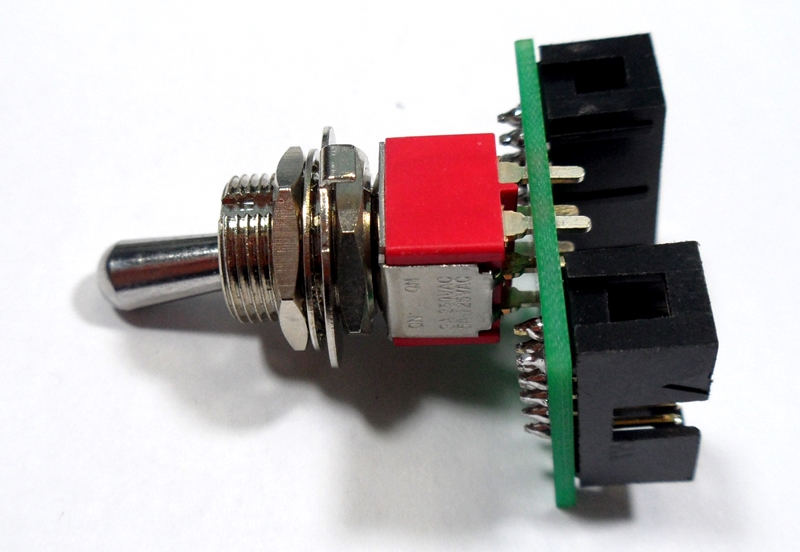
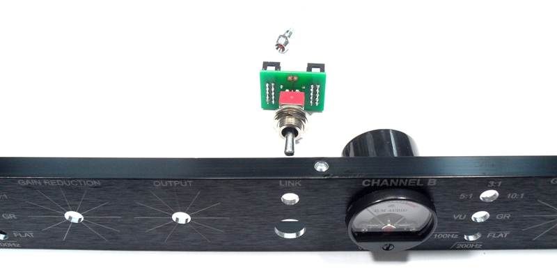
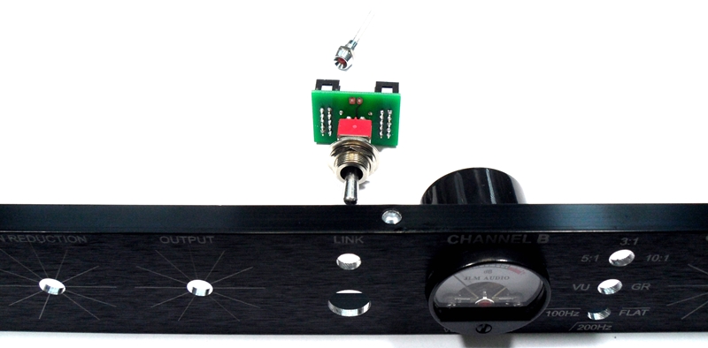
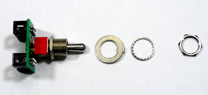
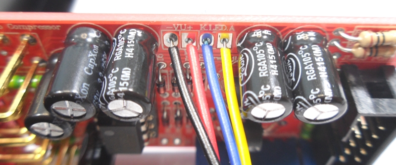
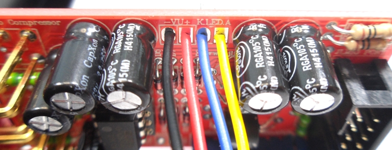
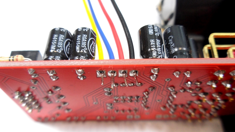
Fit input polarity jumpers as shown for correct phase.
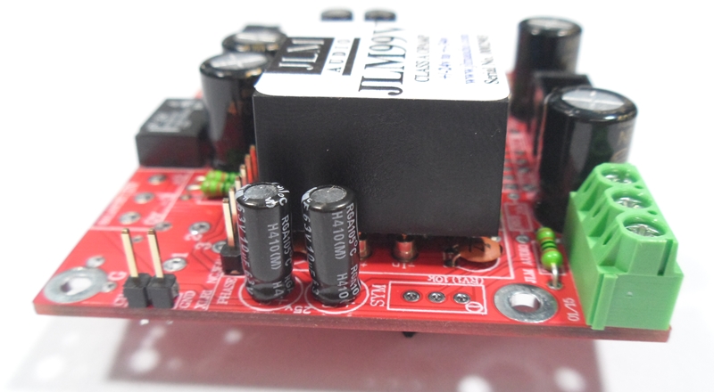
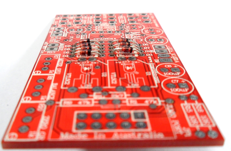
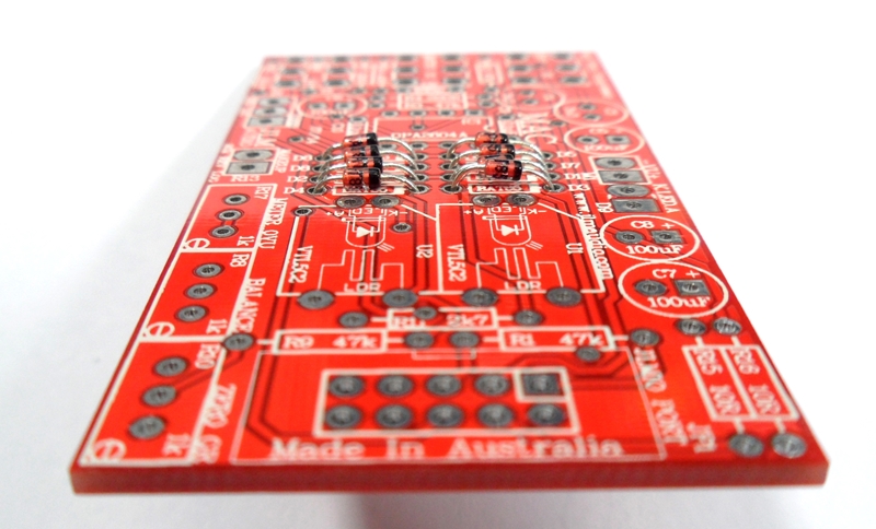
Fit 2 x JLM99v opamps to the 12 sockets on the PCB

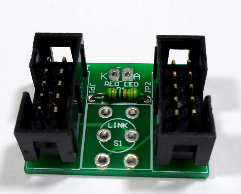
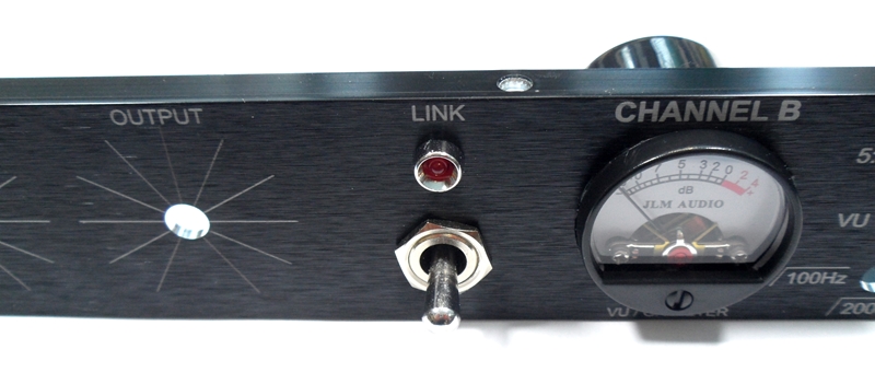
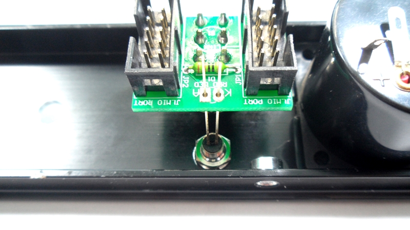
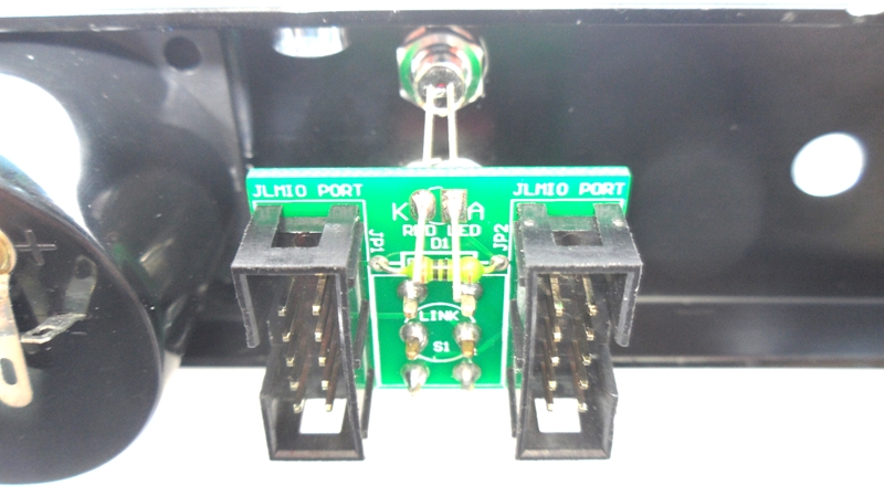
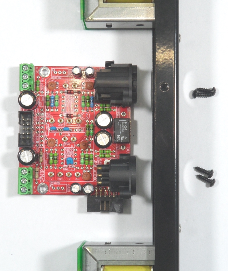
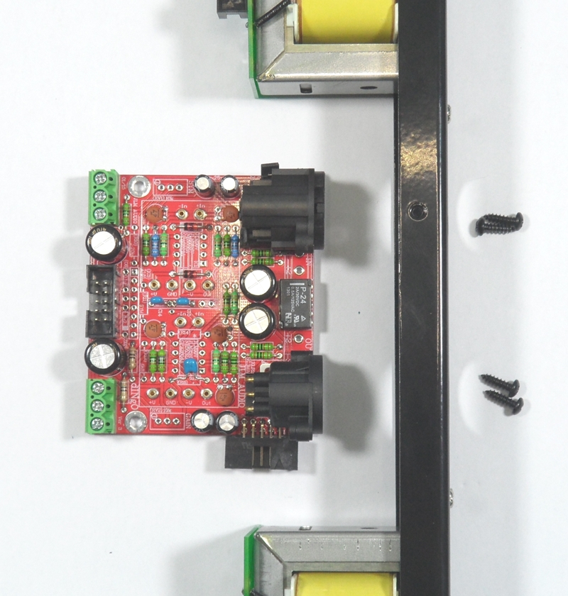
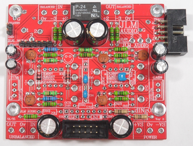
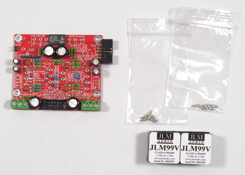
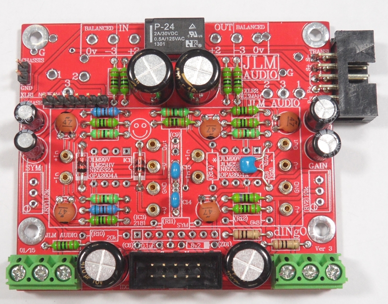
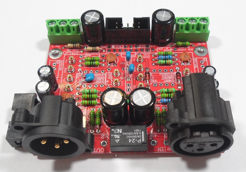
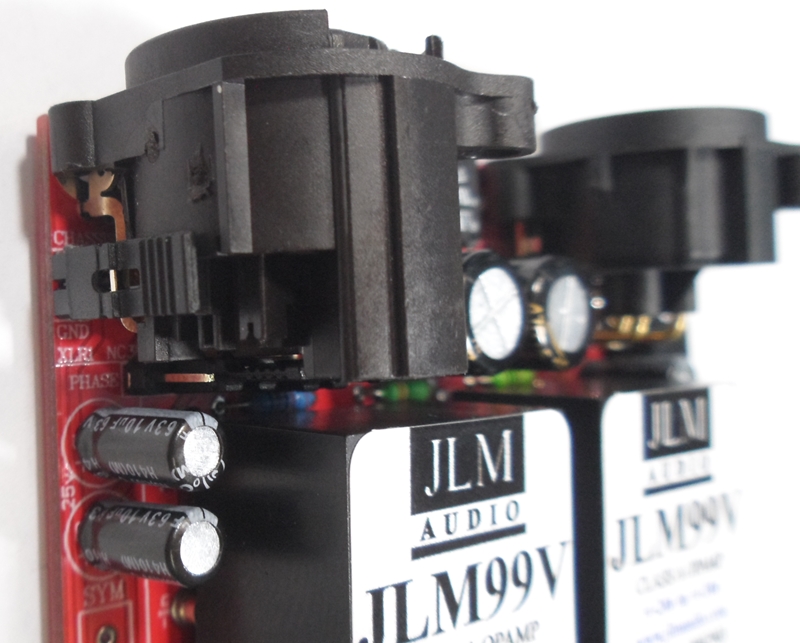
Fit ground link jumper beside XLR. Thid dINgO is built and ready. Build second dINgO and then move on to MAC PCB kits.
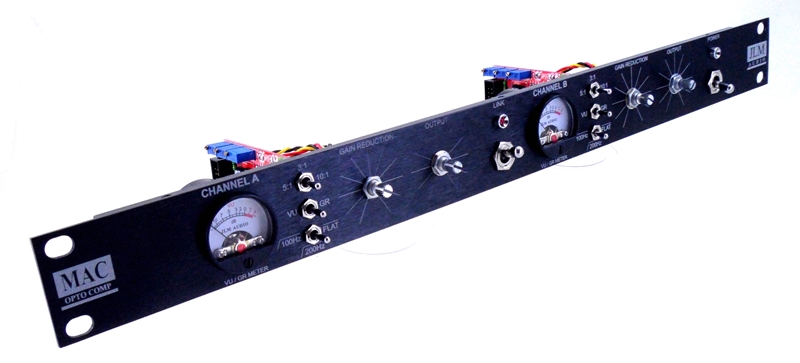
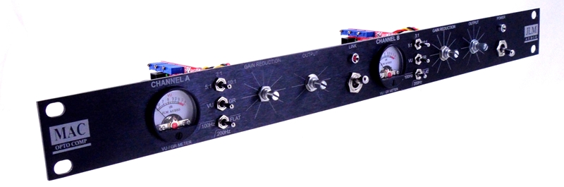
MAC PCB Schematic with MAC alignment
http://www.jlmaudio.com/MAC/MACSCH.pdf
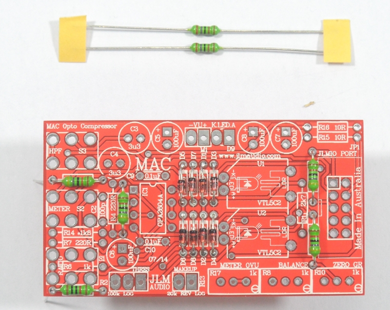
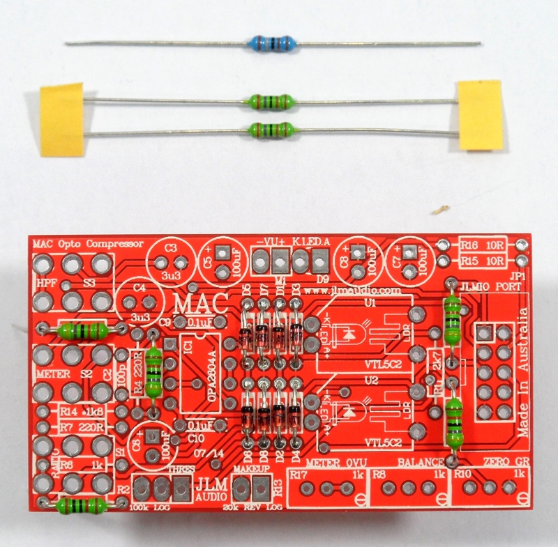
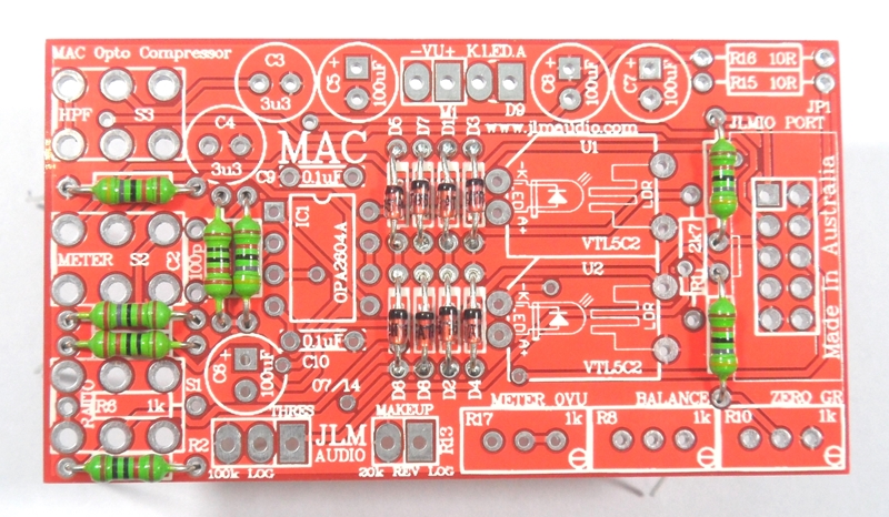
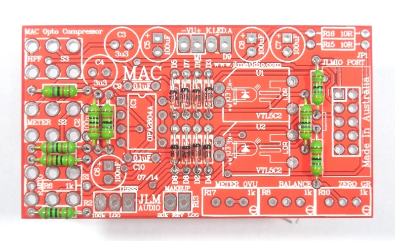
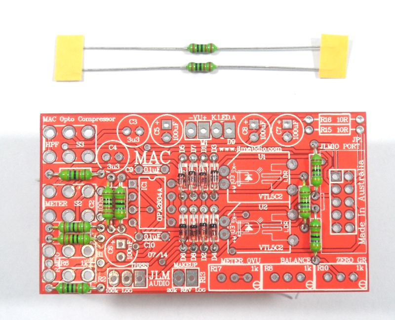
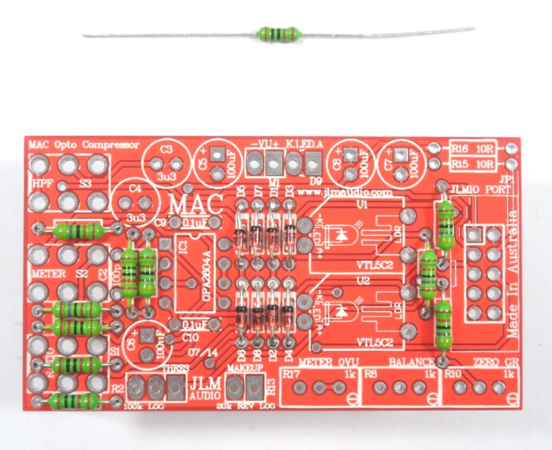
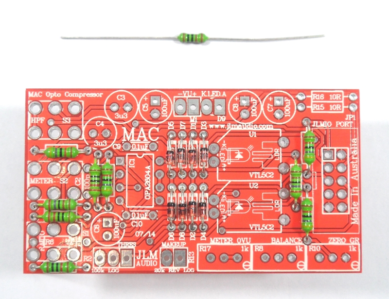
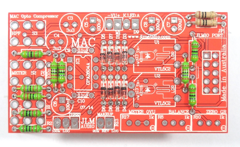
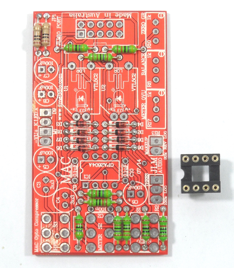
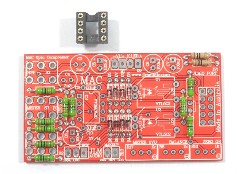
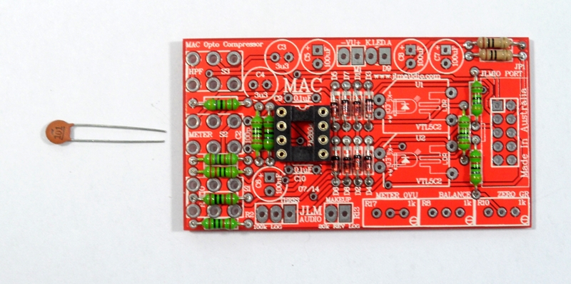
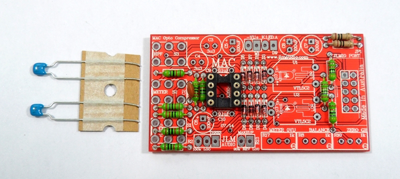
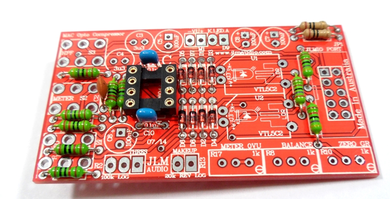
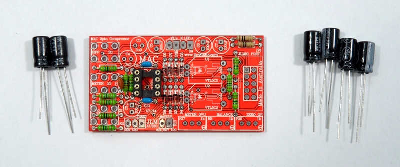
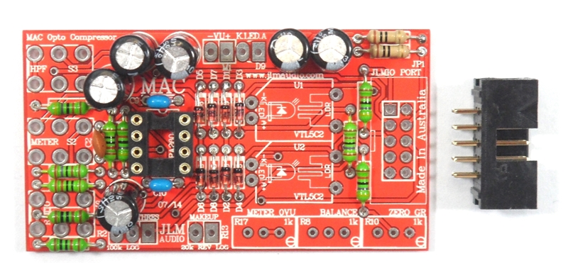
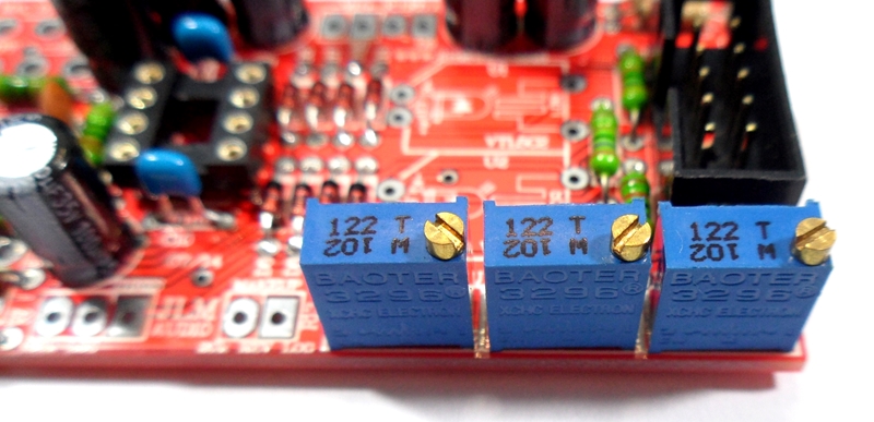
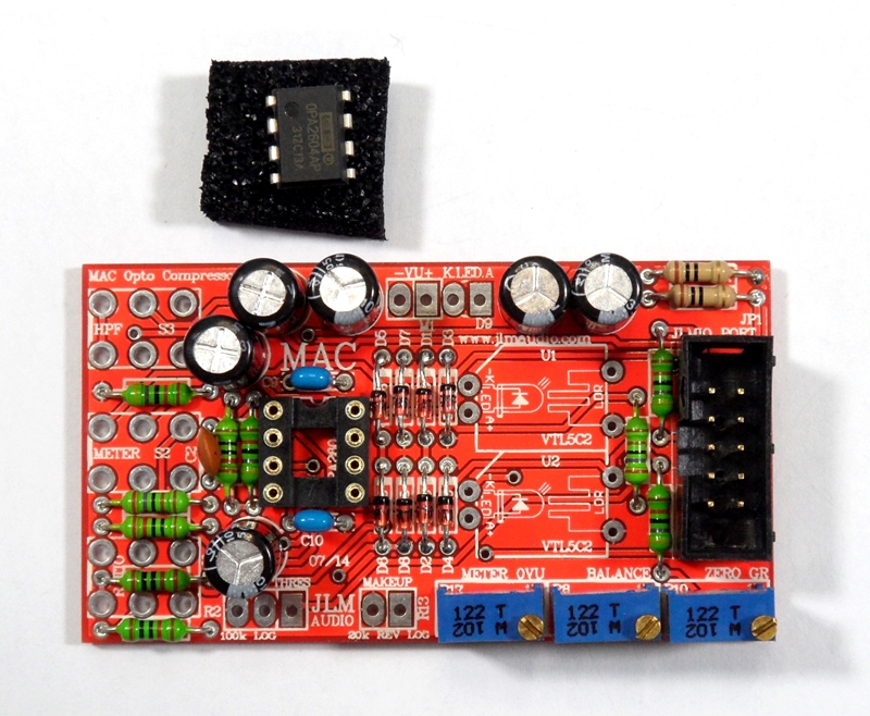
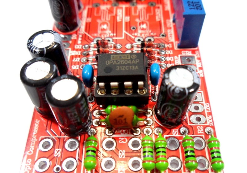
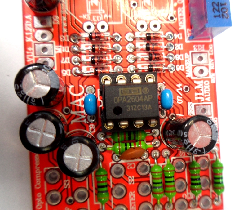
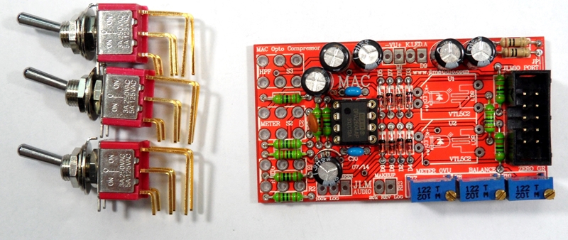
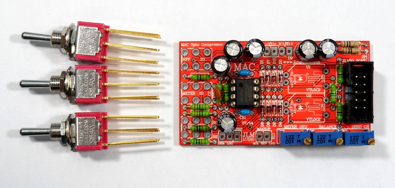
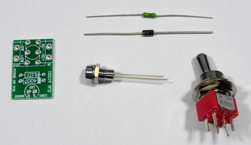
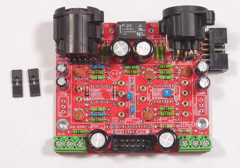
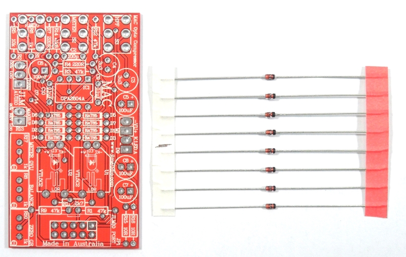
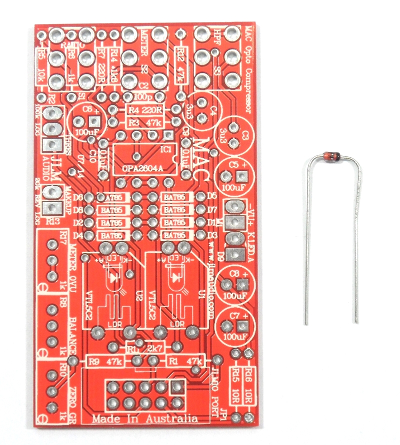
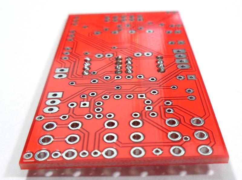
MAC PCB parts kit
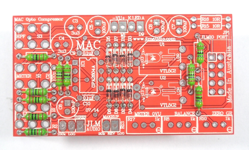
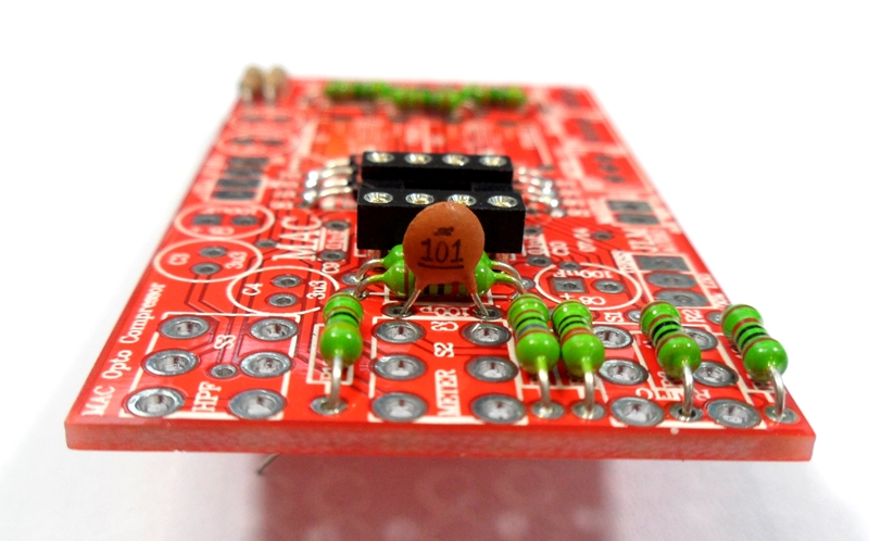
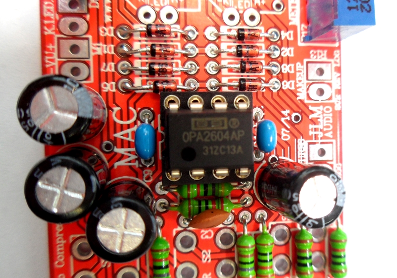
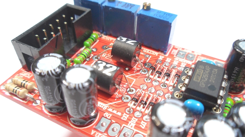
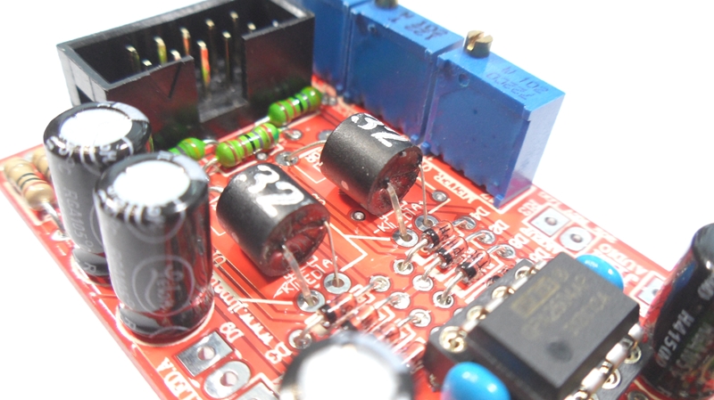
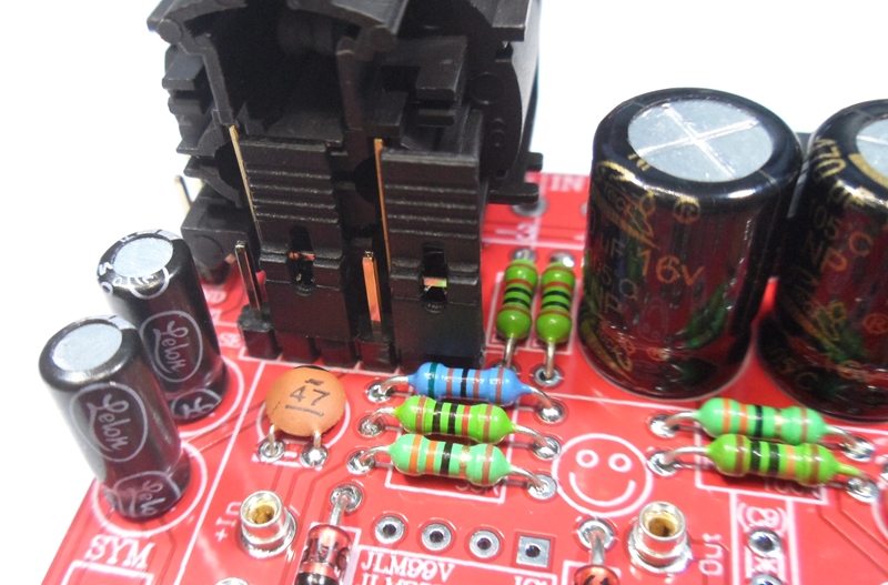
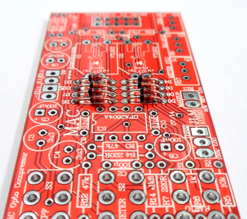
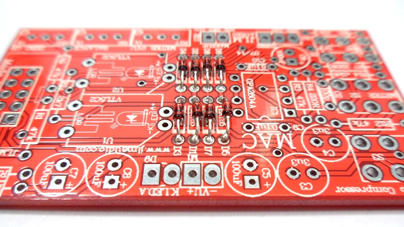
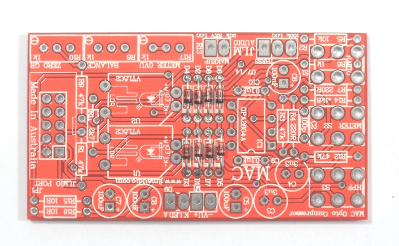
Fit all 8 x BAT85 diodes with there Cathode POLARIZED black stripe matching the white stripe on the MAC PCB overlay
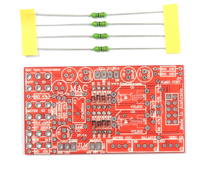
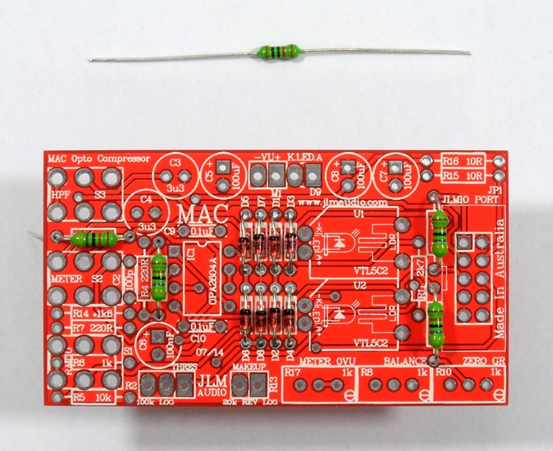
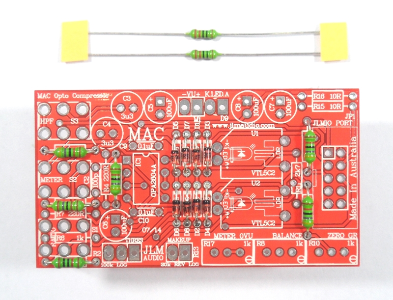
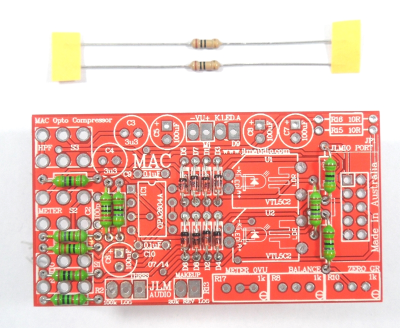
If you are not 100% with resistor colour codes use a multimeter to check values as you place the resistors
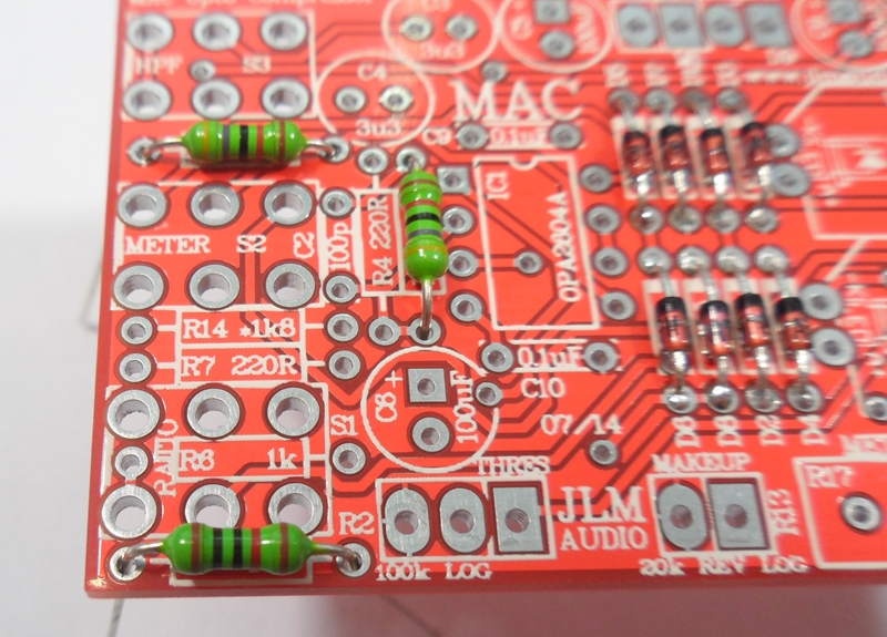
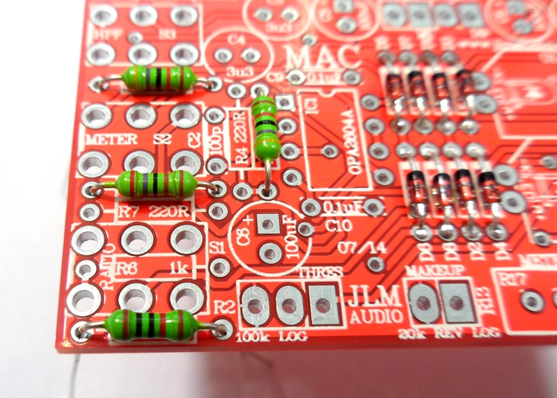
Fit all resistors at once bending the legs sightly outwards to hold them in place. This helps to make sure no resistors are put in the wrong position.
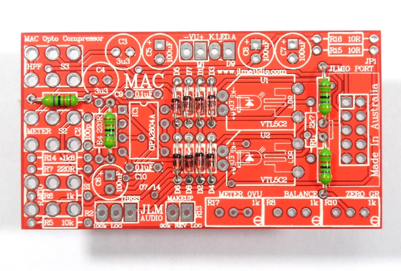
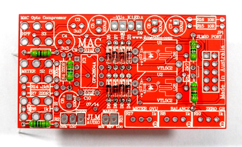
Fit 4 x 47k resistors