LA500A opto comp leveling amp BUILD THREAD 500/51X

Support for JLM Audio Kits

Moderator: Joe Malone

Post Reply
User avatar
Joe Malone
Site Admin
Posts: 2062
Joined: Wed Jan 24, 2007 11:35 pm
Location: Brisbane, Australia
Contact:

LA500A opto comp leveling amp BUILD THREAD 500/51X

Post by Joe Malone »

LA500A kit

LA500A IMPROVEMENTS
3 PCB LAYOUT with no hand wiring just plug in 2 pre-made ribbon cables
NSL32 opto cells made for us to tighter tolerance spec.
Stereo Balance mod now a jumper on LA500SCv3 pcb so can be changed to in seconds.
Slow attack mod built in with leds for slow attack and stereo sidechain link.
78L05 reg so no zero GR adjustment needed between different 51X and 500 racks.

Image

The LA500A is a 500/51x version of our well know MAC opto comp rack version.
For an idea on what the LA500 / MAC comp can do read this AT mag review here

LA500 recall sheet here

Image
Image

LA500A Parts List
http://www.jlmaudio.com/LA500A/LA500A%2 ... 20list.txt

Image

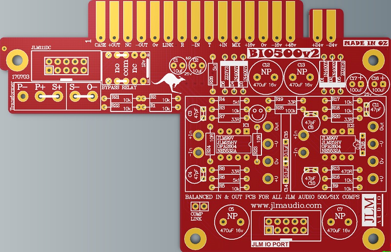
NEW BIO500v2 PCB schematic http://www.jlmaudio.com/BIO500/BIO500v2%20Schematic%20171007.pdf
OLD LA500/BIO500 PCB schematic http://www.jlmaudio.com/LA500/LA500%20Schematic%20120304.pdf

BIO500v2 PCB kit
1. Fully 51X and 500 compatible. 51X pins shorter so PCB will plug into 500 rack without having to cut them off.
3. PCB automatically uses highest power available. +/-16v for 500 and +/-24v for 51X.
4. LA500 PCB also has mix buss out on pin 11 for Radial Workhorse racks.
Image

BIO500v2 PCB.
Notes and Errata
(LA500 PCB renamed to BIO500 PCB as it is used in several products as the Balanced In and Out PCB).
Note 1. Changed R19 51R to 33R give better low frequency response when using JLM111DC and JLM111DC compact output transformer
Note 2. Changed R4 and R6 10k to 5k1
Note 3. Changed R26 4k7 to 5k1
Note 4. Changed OPA2604A to NE5532A. As OPA2604A is now obsolete
Note 5. Added D5 & D6 2 x 3v3 zener diodes so NE5532A runs on 51X power rails
Note 6. Ground Lift pins removed from pcb as most 500 racks short this to 0v so does nothing
Note 7. Comp Link pins do not need to be fitted as the 2 pads are linked on the PCB now
Image

If you are not 100% with resistor colour codes use a multimeter to check values as you place the resistors
Image

Fit all resistors at once bending the legs sightly outwards to hold them in place. This helps to make sure no resistors are put in the wrong position.

Image

Solder all resistors while holding PCB firmly upside down on flat surface.
Image

Cut all resistor legs off at top of the solder joint and double check no solder joints missed soldering.
Image

Fit the 4 x 1N4007 diodes (& 2 x 3v3 Zener diodes BIO500v2). D1 to D6 Diodes are POLARIZED and must go in with there stripe matching the strip on the PCB overlay.
Image

Solder diodes in once you have checked there POLARITY is correct.
Image

Fit 6 x 1mm sockets for 99v opamp. Do NOT press the sockets in. Just let them sit in the holes. Use a piece of cardboard to hold them in while turning the PCB over.
Image
Image

Solder 6 x 1mm sockets in place
Image
Image

Fit and solder DIP8 socket in other opamp position. Make sure the POLARIZED socket matches the PCB overlay.
Image

Fit and solder 3 x 0.1uF MONO caps in place. The 100nF caps are NOT Polarized so can go in either way around.
Caps should be marked 104 or 0.1u or 100n.
27th Dec 2015 a batch of kits has been packed with wrong value 102 1nF caps these will work fine for C14 & C15 but C18 will need to be 104 or 100nF or 0.1uF or larger. Can be any type of mono ceramic or MKT cap as it is only for the meter.
If C18 is smaller than 100nF you will not be able to calibrate the VU meter.
Image
Image

Fit 5 x 47pF ceramic caps in place. The 47pF caps are NOT Polarized so can go in either way around.
Fold 47pF caps down flat to PCB before soldering them.
Image
Image

Fit 12v relay in the POLARITY shown in the photo.
Image

Bend 2 legs out to hold relay in place for soldering
Image

Solder relay in place once POLARITY has been checked
Image

Fit and solder jumper pins in place (Not needed or fitted on Ver 2 PCB.)
Image
Image

Fit and solder IDC headers in the POLARITY shown. Do not reverse. Triangle on header indicates pin 1 which is the square pad on the PCB.
Image

The front opening in the IDC headers should both now be facing as shown below.
Image

Fit and solder Electro caps to PCB. The 2 x 100uF caps are POLARIZED so must have there long positive leg fitted to + marked on PCB overlay.
2 x 10uF and 4 x 470uF caps are NON polar types so can go in either way around on the PCB.
Image
Image
Image

Fit 2 black jumper shunts to the 2 GND LIFT pins and the 2 COMP LINK pins
Image

Fit NE5532A opamp in the correct POLARITY shown. 99v opamp can be fitted now or later. LA500 PCB is ready to go.
Image

Put nuts and bolts etc back into zip lock bag the LA500 PCB kit came in to make sure they are not lost while you build the LA500SCv2 PCB next.
Image

Image

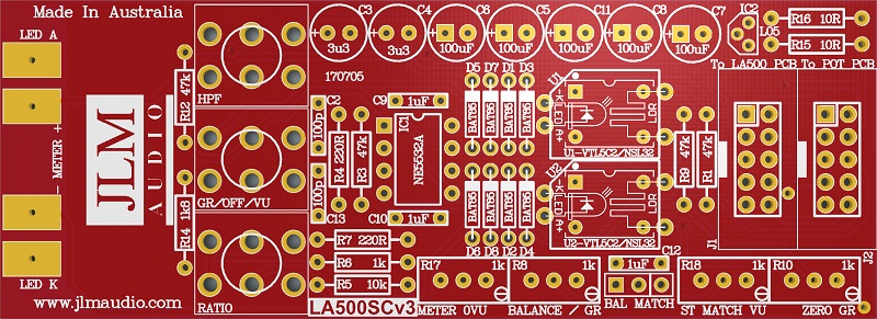
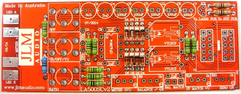
THE LA500SCv3 PCB is the MAC PCB but with no hand wiring and slow attack parts added

NEW LA500SCv3 PCB has some extra holes under U1 & U2 optos which can be used for opto as well
Image

LA500SCv3 schematic at the link below is the same.
http://www.jlmaudio.com/LA500A/LA500SCv3/LA500SCv3%20Schematic.pdf

LA500SCv3 PCB parts kit
Image

LA500SCv3 PCB. PCB overlay has all values and there are no options.
so PCB can be assembled directly from overlay.
Image

Fit all 8 x BAT85 diodes with there Cathode POLARIZED black stripe matching the white stripe on the MAC PCB overlay
Image
Image

Solder all BAT85 diodes while holding PCB firmly upside down on flat surface. Make sure none of the center close pads are NOT shorted together.
Image

Cut all diodes legs off at top of the solder joint and double check no solder joints missed soldering or are shorted together.
Image

If you are not 100% with resistor colour codes use a multimeter to check values as you place the resistors
Image

Fit all resistors at once bending the legs sightly outwards to hold them in place.
This helps to make sure no resistors are put in the wrong position.
Image

Solder all resistors while holding PCB firmly upside down on flat surface.
Cut all resistor legs off at top of the solder joint and double check no solder joints missed soldering.
Image

Fit and solder DIP8 socket in other opamp position. Make sure the POLARIZED socket matches the PCB overlay.
Image
Image

Fit and solder 3 x 1uF MONO caps in place.
Image
Image
Image

Fit 2 x 100pF ceramic caps in place.
Image
Image

Fit and solder IDC headers in the POLARITY shown. Do not reverse. Triangle on header indicates pin 1 which is the square pad on the PCB.
Image

The front opening in the IDC headers should both now be facing as shown below.
Image
Image
Image

Fit and solder Electro caps to PCB. The 5 x 100uF caps are POLARIZED so must have there long positive leg fitted to + marked on PCB overlay.
Image
Image
Image
Image

2 x 3.3uF acaps are NON polar types so can go in either way around on the PCB.
Image
Image
Image
Image
Image

Fit and solder 4 trim pots as shown 1k = 102 code. Place pot so trim screw is in corner shown below
If you have received 103 trim pots please do not use them and contact us for replacements
Image
Image
Image
Image
Image
Image

Fit and solder 3 pin header as shown below
Image
Image

Fit shunt to the 2 pins to the left
Image
Image

Fit and solder 78L05 5v regulator as shown below
Image
Image

Fit and solder NSL32 optos as shown below. Short legs are LED & Long legs are LDR on NSL-32.
The NSL32 Cathode has a dot marked on the case which goes to -K. Be gentle with the wire legs on the opto when shaping them for the PCB.
Note: If you are building a stereo matched pair. Fit the 2 optos in the plastic bag marked U1 into the U1 position on each separate PCB and same for the bag with the U2 pair.
If building just one comp use the 2 optos in the bag and either opto can go into U1 or U2.

Image
Image
Image

Plug in NE5532AP opamp the correct way around as shown below and put the built LA500SCv3 and the 3 switches left over back in the plastic bag and move on to the LA500POTv3 kit.
Image
Image

Image

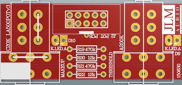
LA500POTv4 PCB holds the Threshold & Makeup pots with there pull switches for slow attack and stereo side chain linking as well as the new leds.
PCB overlay has all values and there are no options.
so PCB can be assembled directly from overlay.
LA500POTv4 schematic here

Image
Image

Fit all resistors at once bending the legs sightly outwards to hold them in place.
This helps to make sure no resistors are put in the wrong position.
NOTE All new kits have new blue led so now have 2 x 120k resistor instead of 2x 470k.

Image
Image
Image
ImageImage
Image
Image
Image

Fit and solder IDC headers in the POLARITY shown. Do not reverse. Triangle on header indicates pin 1 which is the square pad on the PCB.
Image

The front opening in the IDC headers should now be facing as shown below.
Image

Solder one pin and check the connector is sitting flat against PCB. If not reheat while pressing on connector.
Image
Image
Image

Solder all 10 pins and check none have any solder shorts when finished.
Image

WARNING The 2 pots look the same but have very different values and curves so MUST GO IN THE CORRECT POSITIONS.
Image

C20K dual 20k reverse log pot
Image
Image

A200K dual 200k log pot
Image
Image

Cut off locate tabs with cut cutters
Image
Image
Image
Image

You can also cut of the rear tags to leave a bit more room between the front 2 pcbs but it is not essential.
Image
Image
Image

Solder one short leg on each pot to hold them in place.
Image

Solder one pin and check the pot is sitting flat against PCB. If not reheat while pressing on pot until it is sitting correctly.
Image
Image
Image

Solder all pot and switch legs and then check none have been missed.
Image
Image

The 2 LEDs will NOT be fitted until later when the LA500POTv4 PCB is bolted to the bracket and front panel
Image

The ribbon cable can be plugged in and bent into shape and then we are ready to move on to final assembly of the LA500A.
Note if you have the wrong cable in the LA500POT kit click link below to fix it
http://www.jlmaudio.com/forum/viewtopic ... 2980#p2980
Image
Image
Image
Image
Image

Image

Final Assembly of LA500A
Image
Image
Image

Wind the back nut fully down on to the 3 switches. Fit the flat washers on next.
Cut the sides of the middle flat washers with sudecutters so it does not overlap the other washers.
Fit the 3 shake proof washers on next.
Image

Fit nuts and hand tighten to check alignment.
Image

The threaded section of the 3 toggle should be level with the meter section of the stainless steel bracket.
Image

Adjust if needed before tightening the 3 nuts.
Image

Fit Meter into the stainless steelbracket from the front.
Image

Fit front panel and fit 2 meter screws hand tight to hold assembly together.
Image
Image

Fit LA500POTv2 PCB pots into bracket and front panel and do up pot nuts tight to hold assembly together.
Image
Image

Fit the rest of the meter bolts and tighten all 4 bolts gently. Do NOT over-tighten them or you may strip the bracket thread.
Lock-tight can be useful in a always travelling lunchbox to stop them shacking loose.
Image

Bend up meter solder tabs so LA500SCv2 PCB can be slide directly onto the switch legs.
Image
Image
Image

Hold down LA500SCv2 PCB flat against the meter so it is sitting parallel to the front panel and solder one leg of the top and bottom switches to hold in place.
Image

Fold meter tabs down hard against the PCB and solder.
Image

If the tabs spring up use a small screwdriver to hold them down while soldering.
Image
Image

Plug in ribbon cable from LA500POTv2 PCBand push any extra length back in between the 2 PCBs
Image
Image

If everything looks parallel and neat you can now solder all toggle switch legs with the LA500A face down.
Solder each row of 3 and cut the excess off so you can get to the next row under it.
Image

Fit the LA500 PCB to the 4 threaded stand offs with 4 x 3mm x 6mm bolts and lock washers.
Image
Image

Fit short ribbon cable between LA500SCv2 and LA500 PCB
Image
Image

Fit transformer with hardware as shown below
Image
Image
Image
Image
Image
Image
Image

Fit ribbon cable as shown below. Make sure sure end without the cable lock on goes into the transformer socket.
Image
Image
Image
Image

Fit LEDs as shown below. Long LED leg goes to the square solder pad. Do NOT swap the colours as they will not be the correct brightness.
Image

With LED held hard against the front panel grab both legs at the front edge of the PCB holes. Fold both legs at 90 degrees and trim folded part of leg to about 3 to 5mm long.
Image
Image
Image

Solder LED legs to PCB.
Image

Fit JLM99v on the the LA500A PCB
Image
Image

Make sure the pots are turn fully counterclock wise and fit knobs so the line up with MIN dial line.
Image
Image

Compressor setup procedure
1. Set LA to Threshold pot fully CCW, Makeup pot to CCW. Ratio switch to 3:1, Meter switch to VU, HPF switch to FLAT.
2. Apply 1kHz tone to LA500A input so you have the reference level of +4dBu (1.23vac) on the LA500A output between pin 2 & 3 of the XLR.
3. Or plug LA500A output into VU or PPM meter that is calibrated to 0VU = +4dBu. If voltage not correct adjust 1kHz generator level until correct.
4. Adjust meter 0VU trim pot for desired level for 0VU on the meter.
5. Switch Meter switch to GR and adjust Zero GR trim pot for 0VU on meter.
6. Turn up Threshold pot until you have 5dB of compression on meter.
7. Switch Meter switch between GR and VU and adjust Balance trim pot until the same reading is seen in both GR and VU.
8. Your ready to rock.

LA500A opto comp stereo matching mode.

1. Check Both LA500 comp alignments are correct.
2. With 1k tone of same level into both LA500 comps set 0VU on meter switched to VU and turn up Threshold pot to get -5dB on meter and switch to GR to check you have -5dB showing on both meters.
3. Link the comps. If meters move away from each other by more than a +/-1dB move jumper to MATCH end on the compressor which shows more gain reduction on the meter.
NOTE: If comps are very different when linked due to be ordered at different times or batches it is best to swap U1 from one comp with U2 of the other and realign before resorting to stereo match mode. If comps were bought together we will have labelled the opto bags with a U1 and U2 which are already matched pairs

Original balance trim pot will now adjust GR meter level when switched to GR (U2 audio opto) and new ST Match trim pot R18 will adjust VU meter level when switched to VU (U1 meter opto)
Image

1. Setup both comp with 1k tone and set 0VU on meter switched to VU and turn up Threshold pot to get -5dB on meter.
2. Turn threshold pot off on modified comp (fully CCW)
3. Link the comps. Adjust modified VU trim pot until both comps show the same VU meter readings.
4. Switch both comps to GR and adjust modified comp new GR pot until both comps show same GR meter readings.
5. Your comps should be matched.

To check match
1. With 1k tone of same level into both LA500 comps set 0VU on meter switched to VU and turn up Threshold pot to get -5dB on meter and switch to GR to check you have -5dB showing on both meters.
2. Link the comps. If meters move away from each other by more than a +/-0.5dB trim modified comps New GR & New VU trim pot until perfect match when linked.

LA500A opto comp fault finding.

Comp permanently stuck in hard bypass. Then check the meter led lights when switching to GR or VU? If you have a open circuit led in the meter the bypass relay will never operate to lift the hard bypass so you will never hear the comp.
You can add a wire link across the outside meter terminals to see if your hard bypass relay now works.

Check you have +15 to 16v (+19 to 20v 51X) at pin 8 of both NE5532A. Check you have -15v to 16v (-19 to 20v 51X) at pin 4 of both NE5532A.
All other pins of NE5532A on BIO500/LA500 main pcb should be close to 0v. Place black lead from your meter on 0v for all voltage measurement.

Test BIO500/LA500 main pcb by itself by unplugging BIO500/LA500 main pcb ribbon cable from LA500SC pcb and fitting two cut off component leg loops as shown below.
You should have a unity gain audio loop if BIO500/LA500 main pcb is working. This test proves BIO500/LA500 main PCB and output transformer are both working.
You can plug the relay green wire loop in and out to switch between bypass and BIO500 audio path to check audio level is correct.
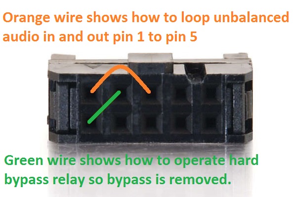
Image
Joe :-)
JLM Audio
Capturing Audio without Injury

Musepro
Posts: 5
Joined: Fri Jan 16, 2015 1:59 am

Re: LA500A opto comp leveling amp BUILD THREAD 500/51X

Post by Musepro »

Meter.JPG
After building 4 of these beauties, I had a few comments others might find useful.

1.) Installation of the new NSL32 optos are quite different than the previous VTL5C2. Seeing no notch or marking indicating opto polarity/position, and having already built a few LA500s and a Mac-Rack, I installed the NSL32s the way the older VTL5C2s were installed; wide spaced opto leads to wide spaced LED PCB pads, narrow leads to narrow spaced LDR pads. This is WRONG. Be sure the widely spaced opto leads (the flats leads) go to the narrow spaced LED pads and the narrow spaced opto leads to the wide spaced LDR pads. Also be sure the 32 faces up and 177 is down. This IS how it is shown in the build thread photos, but I thought I would clarify.

This might not be an issue for newcomers who never used the VTL5C2, or for previously experienced builders who don't assume as I did! lol

2.) I used a bit of component lead to tie the meter contacts to the Mac PCB. There is nothing wrong with doing it the way Joe has demonstrated, its just another option. See my photo.

3.) During assembly, I had a little concern about how close the bottom of the Mac PCB was to the back of the pots. I had concerns of shorting. Sure enough, during calibration, a slight pressure on the PCB caused it to make contact with the back of the pot and short the unit out. It didn't do any damage or cause any harm, but I wanted an extra measure of safety there. I used a small square of double sided foam tape, sticking it to the back of the make-up pot and leaving the tape's film on so that it wouldn't stick to the Mac PCB. This probably isn't an issue once the unit is installed and left alone, but it was a fast way to ensure peace of mind for me.

Alternatively, you could be sure you keep a good sized gap between the PCB and pots when soldering the toggles, though the PCB won't be tight against the meter anymore.

Overall, all 4 kits went together nicely, calibrated easily and worked/sounded perfectly. These new LA500As are the perfect successor to what was already a great little 500 comp. Enjoy!
You do not have the required permissions to view the files attached to this post.

audioguru
Posts: 1
Joined: Tue Mar 03, 2015 9:55 am

Re: LA500A opto comp leveling amp BUILD THREAD 500/51X

Post by audioguru »

Hi Joe!

Just finished building my LA500A, I have a question about the small LA500SCv2 PCB, there is a procedure to adjust the 4 trim pots for the VU meter but on the procedure there is one trim that you don't talk about that is R18 ST Match Up trim, is there any setup procedure to do with that trim?

Thanks.

Pascal

User avatar
Joe Malone
Site Admin
Posts: 2062
Joined: Wed Jan 24, 2007 11:35 pm
Location: Brisbane, Australia
Contact:

Re: LA500A opto comp leveling amp BUILD THREAD 500/51X

Post by Joe Malone »

audioguru wrote:Hi Joe!

Just finished building my LA500A, I have a question about the small LA500SCv2 PCB, there is a procedure to adjust the 4 trim pots for the VU meter but on the procedure there is one trim that you don't talk about that is R18 ST Match Up trim, is there any setup procedure to do with that trim?

Thanks.

Pascal
This is the stereo match mod from the original LA500 already built on to the PCB so it can be done in seconds.

LA500A opto comp stereo matching mode.

1. Check Both LA500 comp alignments are correct.
2. With 1k tone of same level into both LA500 comps set 0VU on meter switched to VU and turn up Threshold pot to get -5dB on meter and switch to GR to check you have -5dB showing on both meters.
3. Link the comps. If meters move away from each other by more than a +/-1dB move jumper to MATCH end on the compressor which shows more gain reduction on the meter.
NOTE: If comps are very different when linked due to be ordered at different times or batches it is best to swap U1 from one comp with U2 of the other and realign before resorting to stereo match mode. If comps were bought together we will have labelled the opto bags with a U1 and U2 which are already matched pairs

Original balance trim pot will now adjust GR meter level when switched to GR (U2 audio opto) and new ST Match trim pot R18 will adjust VU meter level when switched to VU (U1 meter opto)
Image

1. Setup both comp with 1k tone and set 0VU on meter switched to VU and turn up Threshold pot to get -5dB on meter.
2. Turn threshold pot off on modified comp (fully CCW)
3. Link the comps. Adjust modified VU trim pot until both comps show the same VU meter readings.
4. Switch both comps to GR and adjust modified comp new GR pot until both comps show same GR meter readings.
5. Your comps should be matched.

To check match
1. With 1k tone of same level into both LA500 comps set 0VU on meter switched to VU and turn up Threshold pot to get -5dB on meter and switch to GR to check you have -5dB showing on both meters.
2. Link the comps. If meters move away from each other by more than a +/-0.5dB trim modified comps New GR & New VU trim pot until perfect match when linked.
Joe :-)
JLM Audio
Capturing Audio without Injury

CGMix
Posts: 2
Joined: Wed Apr 08, 2015 9:28 am

Re: LA500A opto comp leveling amp BUILD THREAD 500/51X

Post by CGMix »

This may have already been answered, but I just couldn't seem to find where. I have a regular LA500, and would like another. Could I pair one of these new ones with mine? Or would I need to update the opto cells in mine for it to match?

User avatar
Joe Malone
Site Admin
Posts: 2062
Joined: Wed Jan 24, 2007 11:35 pm
Location: Brisbane, Australia
Contact:

Converting wrong pot cable to work.

Post by Joe Malone »

A recent batch of LA500A kits were packed with 2 x LA500 MAIN PCB to LA500SC cables
Below shows how to convert one of the cables to be the correct AL500SC to LA500POT cable

Hold each side of the IDC header tightly and cut the cable lock in 2 places as shown
Image
Image

Unfold cable
Image

Cut 2 left over cable lock pieces flush
Image
Image

Repeat for other end of cable
Joe :-)
JLM Audio
Capturing Audio without Injury

G-Sun
Posts: 39
Joined: Mon Dec 12, 2011 3:48 am
Location: Norway
Contact:

Re: LA500A opto comp leveling amp BUILD THREAD 500/51X

Post by G-Sun »

Just finished assembled the LA500A.
Very good manual and instructions. Did a few mistakes, but that's my fault.

Now, tried to adjust it for correct setup.
That's harder for me. Will fine-read and try again.
Should of course bought an extender, but saved a few bucks for not :)

Edit: Made it through the setup. Unit working fine. Initial impressions are very good.
Thank you!
www.g-sun.no/en/

johntunes
Posts: 1
Joined: Mon Oct 05, 2015 5:03 am

LA500a - No gain reduction indicated on meter?

Post by johntunes »

Hello forum members,

After recently completing my first JLM LA500a kit, I am pleased to say the unit is functioning sonically and sounds great.

Unfortunately, it is not registering any visual gain reduction on the meter when set to GR mode. The meter sits at 0. I also noticed the led's seem particularly dim. I would expect them to be a bit brighter.
Is there any place on this site where I could possible get some advice on how to proceed with troubleshooting the build?

Any advice or suggestions would be greatly appreciated.
thanks in advance,

John

User avatar
Joe Malone
Site Admin
Posts: 2062
Joined: Wed Jan 24, 2007 11:35 pm
Location: Brisbane, Australia
Contact:

Re: LA500a - No gain reduction indicated on meter?

Post by Joe Malone »

johntunes wrote:Hello forum members,

After recently completing my first JLM LA500a kit, I am pleased to say the unit is functioning sonically and sounds great.

Unfortunately, it is not registering any visual gain reduction on the meter when set to GR mode. The meter sits at 0. I also noticed the led's seem particularly dim. I would expect them to be a bit brighter.
Is there any place on this site where I could possible get some advice on how to proceed with troubleshooting the build?

Any advice or suggestions would be greatly appreciated.
thanks in advance,

John
1. my la500 vu meter is not registering any gain reduction although I can hear it working. it simply sits at 0vu. (if i flick the switch to the VU setting, I do see audio out levels)
[Joe] Ok so the meter lights and turning threshold up turns the output level down and makeup does turn the level back up ok? If only the GR meter doesn't work either the 78L05 5v reg is in wrong way or U2 opto is in wrong way around? If not sure send me by email some large clear in focus well-lit photos so I can check it over for you.

2. my gold and blue led's seem to be dimmer than I would expect and the blue one seems to flicker.
[Joe] We do light the led so they only light there colour up without being like a neon light. If you want them brighter you can short out with a wire link the 2 resistors between the threshold and makeup pots that are closest to the front panel. R21 & R22. IF you led is flickering I would check all solder joints are soldered properly first.
Image

** my biggest concern is that as I was assembling, I discovered my MAC circuit board had a long extension with leads that looked nothing like the one in the build thread. I eventually clipped it off in order to make it fit behind the meter. I'm unable to determine what that section was for as it doesn't seem possibly to fit it in the unit, but I'm also worried I might have messed something up in the process.
[Joe]New LA500SCv3 PCB has extra piece used for MAC comp only that is cut off along white line with sidecutters when used for LA500A. There is no damage that can be done even if you cut a few millimetres either way. LA500SCv3 PCB also has the missing track fixed so NO wire link from the IDC header to the solder via is needed.
Image
Joe :-)
JLM Audio
Capturing Audio without Injury

G-Sun
Posts: 39
Joined: Mon Dec 12, 2011 3:48 am
Location: Norway
Contact:

Re: LA500A opto comp leveling amp BUILD THREAD 500/51X

Post by G-Sun »

One question:
I tried the 99V in the LA500A as a second gainstage (preamp + preamp).
Is the sound of it the same as would be in the BA or Dual99V?

I noticed some dullness in the mid-range and some hi-frequenzy attenuation (really noticeable on a small condenser on an acoustic guitar).

This is just fine for typical makup-gain duty, and give the unit some desired sonics, yet as preamp I kind of wandered.
www.g-sun.no/en/

User avatar
Joe Malone
Site Admin
Posts: 2062
Joined: Wed Jan 24, 2007 11:35 pm
Location: Brisbane, Australia
Contact:

Re: LA500A opto comp leveling amp BUILD THREAD 500/51X

Post by Joe Malone »

G-Sun wrote:One question:
I tried the 99V in the LA500A as a second gainstage (preamp + preamp).
Is the sound of it the same as would be in the BA or Dual99V?

I noticed some dullness in the mid-range and some hi-frequenzy attenuation (really noticeable on a small condenser on an acoustic guitar).

This is just fine for typical makup-gain duty, and give the unit some desired sonics, yet as preamp I kind of wandered.
I don't really understand what you mean by "I tried the 99V in the LA500A as a second gainstage (preamp + preamp)." ?

As the LA500A has one balanced input buffer no gain best done with OPA2604AP for best headroom. Then a makeup gain stage using JLM99v which is needed to drive the output transformer correctly.
Joe :-)
JLM Audio
Capturing Audio without Injury

G-Sun
Posts: 39
Joined: Mon Dec 12, 2011 3:48 am
Location: Norway
Contact:

Re: LA500A opto comp leveling amp BUILD THREAD 500/51X

Post by G-Sun »

Joe Malone wrote:
G-Sun wrote:One question:
I tried the 99V in the LA500A as a second gainstage (preamp + preamp).
Is the sound of it the same as would be in the BA or Dual99V?

I noticed some dullness in the mid-range and some hi-frequenzy attenuation (really noticeable on a small condenser on an acoustic guitar).

This is just fine for typical makup-gain duty, and give the unit some desired sonics, yet as preamp I kind of wandered.
I don't really understand what you mean by "I tried the 99V in the LA500A as a second gainstage (preamp + preamp)." ?

As the LA500A has one balanced input buffer no gain best done with OPA2604AP for best headroom. Then a makeup gain stage using JLM99v which is needed to drive the output transformer correctly.
Sorry, for not making myself clear. I used a ssl9k preamp, then into the la500a, threshold 0 (left/ccw). Then setting the ssl9k low, using the makup-gain in the la500a as a second gainstage.
www.g-sun.no/en/

kante1603
Posts: 86
Joined: Wed Jan 20, 2010 6:12 pm

Re: LA500A opto comp leveling amp BUILD THREAD 500/51X

Post by kante1603 »

Hi Joe,

another pair finished here.All great.Top sounding,slow attack is a great thing.

One little issue:Both blue leds don't seem to work in link mode.
Before I check for accidently reversed leds (I thought they were in the right way,but who knows :roll: ) I wanted to ask if 1meg (formed by 2 x 470k) as preresistors isn't a bit on the high side?
I can't seem to find a schematic for the switch pcb,so the led is switched directly from the pot switch (pulled out),yes?
Is it run from the pos. or neg. rail?
And it should light up when spot is pulled,no matter if run as single module or pair,no?

Thank you in advance,

best regards,

Udo.

User avatar
Joe Malone
Site Admin
Posts: 2062
Joined: Wed Jan 24, 2007 11:35 pm
Location: Brisbane, Australia
Contact:

Re: LA500A opto comp leveling amp BUILD THREAD 500/51X

Post by Joe Malone »

kante1603 wrote:Hi Joe,

another pair finished here.All great.Top sounding,slow attack is a great thing.

One little issue:Both blue leds don't seem to work in link mode.
Before I check for accidently reversed leds (I thought they were in the right way,but who knows :roll: ) I wanted to ask if 1meg (formed by 2 x 470k) as preresistors isn't a bit on the high side?
I can't seem to find a schematic for the switch pcb,so the led is switched directly from the pot switch (pulled out),yes?
Is it run from the pos. or neg. rail?
And it should light up when spot is pulled,no matter if run as single module or pair,no?

Thank you in advance,

best regards,

Udo.
HI Udo
Thanks for the great review here and on our web site :-)

Yes we have just found the latest batch of 10000 blue leds (which are supposed to the be the same ones we always get) are different. They need total 240k = 2 x 120k.

Remove one 470k and place it under the pcb across the other 470k and link where the 470k was to get 235k with existing kits and the correct brightness blue leds.

All new kits from December 2015 will now have 2 x 120k instead of the 2 x 470k. Sorry for the stuff up.
Joe :-)
JLM Audio
Capturing Audio without Injury

G-Sun
Posts: 39
Joined: Mon Dec 12, 2011 3:48 am
Location: Norway
Contact:

Re: LA500A opto comp leveling amp BUILD THREAD 500/51X

Post by G-Sun »

Great compressor.

Tried to write a review myself,
but on missing star-rating the review was deleted..

A second forum-meta: Using first post as manual is maybe not a good idea.
Makes loading posts a pita.

Thank you very much Joe!
www.g-sun.no/en/

Post Reply