Page 1 of 7
Stereo VU meter kit BUILD THREAD
Posted: Mon Nov 05, 2012 6:48 pm
by Joe Malone
Re: Stereo VU meter kit BUILD THREAD
Posted: Thu Aug 29, 2013 9:56 am
by slnstudios
Hey guys, i have built one of these kits and was working perfectly until the other day when it lit up and sound passed through the vu meters but no movement? I rectified the problem by putting a high dB signal through which jumped the meters to +3dB and begun moving normally again to music.. The meters have been calibrated to -18 dBFS out of protools with the rear trim pots.. Is there a reason for this? and if there is, is there a way to fix it... Also, what do the two front flathead screws do that are under each meter? are these suppose to fully line up with the holes drilled in the front panel as only half of the screws can be seen through the hole.. Cheers, Shane.
Re: Stereo VU meter kit BUILD THREAD
Posted: Mon Sep 16, 2013 9:55 pm
by Joe Malone
slnstudios wrote:Hey guys, i have built one of these kits and was working perfectly until the other day when it lit up and sound passed through the vu meters but no movement? I rectified the problem by putting a high dB signal through which jumped the meters to +3dB and begun moving normally again to music.. The meters have been calibrated to -18 dBFS out of protools with the rear trim pots.. Is there a reason for this? and if there is, is there a way to fix it. Cheers, Shane.
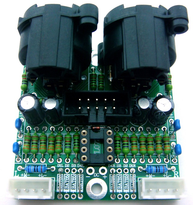
From testing Shane's VU buffer kit which was at very near full gain setting we found the opamp can latch up depending on how the power supply was powered up. The latch up shows as the meters not responding until a loud input signal makes the meter suddenly start and work normally. This is fixed by making the half volts rail lower resistance so it can stop the latch up. All that was needed to fix this is to change the 2 x 47k in the centre of the XLRs R10 & R11 that make the half volts rails to 2 x 10k. If the VU buffer is built already adding 2 x 10k to 12k resistors under the PCB across the existing 2 x 47k resistors will work fine. New kits will have these resistor values added in and when the latest batch of PCB's run out we will change the overlay values to the new values. This info has been added to the VU2 Stereo buffer kit Build thread.
Special Calibration on vu meters
Posted: Tue Nov 11, 2014 3:37 pm
by sebasbetap
Hello Joe,
Thanks for offering us this wonderful kit.
I have a question, thanks for your time answering it.
I want to calibrate each vu meter sepparately. One for mixing in -14dBFS and one for master in -9dBFS. Can I do that by simply turn the 5K pots? Or do I have to
do something different?
Thanks, again.
Sebastian Betancur
Re: Special Calibration on vu meters
Posted: Tue Nov 11, 2014 4:41 pm
by Joe Malone
sebasbetap wrote:Hello Joe,
Thanks for offering us this wonderful kit.
I have a question, thanks for your time answering it.
I want to calibrate each vu meter sepparately. One for mixing in -14dBFS and one for master in -9dBFS. Is there a way to do that on this kit?
Thanks, again.
Sebastian Betancur
Each Left and Right VU meter has its own 25 turn trim pot to cal it over large range.
If you mean to you want to switch the 2 meters between 2 level settings then leave the trim pots of the PCB and bring the outside trim pot pads out to wires to a DPDT toggle switch with 2 extra trimpots so you can switch between 2 reference levels.
Re: Stereo VU meter kit BUILD THREAD
Posted: Tue Nov 11, 2014 5:50 pm
by sebasbetap
Thanks Joe for your swift repply!
I have already buyed and builded this kit. I'll try to calibrate each vu meter in a separate way with the 5k pot as you said.
I have another question. I want to understand this vu meter electronic operation. Do you have the electronic schematic of this project?
And can you let us take a peek on it?.
Thanks Again,
Sebas Betancur
Re: Special Calibration on vu meters
Posted: Thu Nov 13, 2014 2:26 pm
by sebasbetap
Joe Malone wrote:sebasbetap wrote:Hello Joe,
Thanks for offering us this wonderful kit.
I have a question, thanks for your time answering it.
I want to calibrate each vu meter sepparately. One for mixing in -14dBFS and one for master in -9dBFS. Is there a way to do that on this kit?
Thanks, again.
Sebastian Betancur
Each Left and Right VU meter has its own 25 turn trim pot to cal it over large range.
If you mean to you want to switch the 2 meters between 2 level settings then leave the trim pots of the PCB and bring the outside trim pot pads out to wires to a DPDT toggle switch with 2 extra trimpots so you can switch between 2 reference levels.
Sorry Joe for so many questions, jaja
Where can I find a dBFS reference to calibrate my stereo Vu meter?
The link you posted on the Vu buffer kit thread
http://www.minorshill.co.uk/PC/Meters/S ... 20Test.zip
is not working.
I have seen the schematic of that kit (
http://www.jlmaudio.com/VU%20Buffer%20Circuit.gif). Is it the same of this one but in a double way?
Greetings from Colombia.
Sebas Betancur
Re: Special Calibration on vu meters
Posted: Thu Nov 13, 2014 2:41 pm
by Joe Malone
sebasbetap wrote:Joe Malone wrote:sebasbetap wrote:Hello Joe,
Thanks for offering us this wonderful kit.
I have a question, thanks for your time answering it.
I want to calibrate each vu meter sepparately. One for mixing in -14dBFS and one for master in -9dBFS. Is there a way to do that on this kit?
Thanks, again.
Sebastian Betancur
Each Left and Right VU meter has its own 25 turn trim pot to cal it over large range.
If you mean to you want to switch the 2 meters between 2 level settings then leave the trim pots of the PCB and bring the outside trim pot pads out to wires to a DPDT toggle switch with 2 extra trimpots so you can switch between 2 reference levels.
Sorry Joe for so many questions, jaja
Where can I find a dBFS reference to calibrate my stereo Vu meter?
The link you posted on the Vu buffer kit thread
http://www.minorshill.co.uk/PC/Meters/S ... 20Test.zip
is not working.
I have seen the schematic of that kit (
http://www.jlmaudio.com/VU%20Buffer%20Circuit.gif). Is it the same of this one but in a double way?
Greetings from Colombia.
Sebas Betancur
Schematic is the same for VU buffer and VU2.
There is no exact setting for which dBFS. It is whatever works for your setup.
But most people try to use either K14 which would be 0VU = -14dBFS or K18 which would be 0VU = -18dBFS
Connecting to Volume Knob
Posted: Thu Jan 22, 2015 8:40 pm
by navehgrofi
Hi Joe,
So I bought the buffer kit (waiting for it to arrive).
just to be clear, im building kind of a Volume Box, which includes the Vu meters and a volume Knob for speakers Levels...
so Basically, i need to wire the inputs of the Vu buffer also the the volume knob?
the meters will give me the volume of the inputs only right?
thanks
Naveh
Re: Connecting to Volume Knob
Posted: Thu Jan 22, 2015 8:55 pm
by Joe Malone
navehgrofi wrote:Hi Joe,
So I bought the buffer kit (waiting for it to arrive).
just to be clear, im building kind of a Volume Box, which includes the Vu meters and a volume Knob for speakers Levels...
so Basically, i need to wire the inputs of the Vu buffer also the the volume knob?
the meters will give me the volume of the inputs only right?
thanks
Naveh
Yes if you wire the VU buffer input across the input to the volume Box.
Re: Stereo VU meter kit BUILD THREAD
Posted: Sun Mar 15, 2015 4:42 am
by navehgrofi
Hi Jo
Do the 34 mm meters you sale has rectifiers in them?
i just bought 2 of them (not yours)
and for some reason i don't have any meters reading (still waiting to verify i have audio coming out (waiting for parts)
im guessing this might be the issue but I'm not sure
Naveh
Re: Stereo VU meter kit BUILD THREAD
Posted: Mon Mar 16, 2015 3:14 am
by navehgrofi
Hi Jo
I have another Question
Can You guide me please through the connection of the following parts:
inputs (balanced Trs lines) - i connected them to the mounted TRS inputs i orders from you.
Now I have XLR outputs that need to go through a 24 steps Ladder attenuator for Volume control.
the Attenuator have GND, Input, Output for each channel
So TRS Tip (from board) connects to the Attenuator input and attenuator output connects to Pin 2 in Xlr output right?
so what about pin 1 and 3 in the Xlr Output and the GND on the attenuator?
i also cannot see any meters movement...
Thanx...Naveh
Re: Stereo VU meter kit BUILD THREAD
Posted: Mon Mar 16, 2015 3:21 pm
by Joe Malone
navehgrofi wrote:Hi Jo
Do the 34 mm meters you sale has rectifiers in them?
i just bought 2 of them (not yours)
and for some reason i don't have any meters reading (still waiting to verify i have audio coming out (waiting for parts)
im guessing this might be the issue but I'm not sure
Naveh
Our 34mm meters do NOT have rectifiers in them. You need external rectifier or our VU buffer and peak led kit or VU2 stereo buffer kit to make them work with audio.
Re: Stereo VU meter kit BUILD THREAD
Posted: Mon Mar 16, 2015 3:33 pm
by Joe Malone
navehgrofi wrote:Hi Jo
I have another Question
Can You guide me please through the connection of the following parts:
inputs (balanced Trs lines) - i connected them to the mounted TRS inputs i orders from you.
Now I have XLR outputs that need to go through a 24 steps Ladder attenuator for Volume control.
the Attenuator have GND, Input, Output for each channel
So TRS Tip (from board) connects to the Attenuator input and attenuator output connects to Pin 2 in Xlr output right?
so what about pin 1 and 3 in the Xlr Output and the GND on the attenuator?
i also cannot see any meters movement...
Thanx...Naveh
Sounds like you have a unbalanced stereo ladder atten so either you need one stereo atten per channel to keep the proper balancing or use our dingo pup kit to take the balanced input to unbalance for the attenuator and then the unbalanced output from atten to dingo pup to convert back to balanced.
Never run VU meters directly across the output of a passive attenuator without a buffer otherwise meters will add distortion to the signal. Using VU Buffer will isolate and stop the distortion on the audio.
You can do a pseudo balanced attenuater using the unbalanced attenuator by wiring
Tip to atten in and out to XLR pin 2
Ring to atten GND and XLR pin 3
Sleeve to XLR pin 1
This pseudo balanced atten will work as volume but any noise cancellation will vary greatly depending on the length of the output XLR cables and so is not recommended.
Re: Stereo VU meter kit BUILD THREAD
Posted: Mon Mar 16, 2015 11:45 pm
by navehgrofi
navehgrofi wrote:
Hi Jo
I have another Question
Can You guide me please through the connection of the following parts:
inputs (balanced Trs lines) - i connected them to the mounted TRS inputs i orders from you.
Now I have XLR outputs that need to go through a 24 steps Ladder attenuator for Volume control.
the Attenuator have GND, Input, Output for each channel
So TRS Tip (from board) connects to the Attenuator input and attenuator output connects to Pin 2 in Xlr output right?
so what about pin 1 and 3 in the Xlr Output and the GND on the attenuator?
i also cannot see any meters movement...
Thanx...Naveh
Sounds like you have a unbalanced stereo ladder atten so either you need one stereo atten per channel to keep the proper balancing or use our dingo pup kit to take the balanced input to unbalance for the attenuator and then the unbalanced output from atten to dingo pup to convert back to balanced.
Never run VU meters directly across the output of a passive attenuator without a buffer otherwise meters will add distortion to the signal. Using VU Buffer will isolate and stop the distortion on the audio.
You can do a pseudo balanced attenuater using the unbalanced attenuator by wiring
Tip to atten in and out to XLR pin 2
Ring to atten GND and XLR pin 3
Sleeve to XLR pin 1
This pseudo balanced atten will work as volume but any noise cancellation will vary greatly depending on the length of the output XLR cables and so is not recommended.
thanks a lot for the answers Jo
2 more questions please:
1. im successfully having meters read, but even with the highest gain position i cannot bring the needles over -3 dB (I'm sending high volume 1 kHz sine wave)
2. is this setup recommended:
Audio Device outputs (UnBalanced) through TRS Line (Sleeve not connected?) to VU STEREO Inputs, then Pseudo Balanced at ten wiring to XLR outputs (lines to speakers are only 1 meters or less long)
or should i use Fully balanced lines to the inputs?


 Enjoy
Enjoy