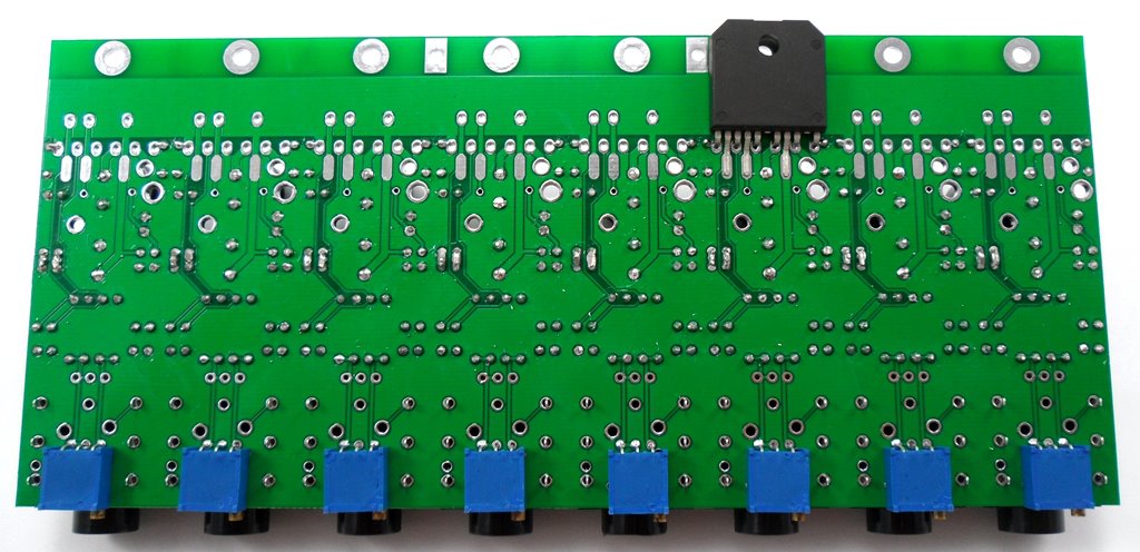
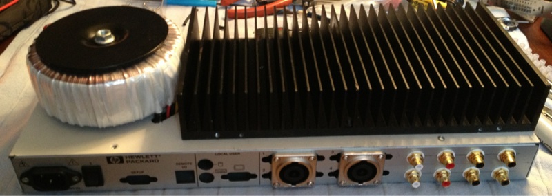
Chips on the PCB underside, mounted to a piece of 75x35x9 unequal angle aluminium with two CPU coolers attached. Angle will attach firmly to the chassis, which may help with dissipation a little... though the thermal resistance across the powder coating will be high I'd say so the assistance is likely to be minimal. On that point, the bridge rectifier is similarly mounted to the chassis; will this provide enough cooling?
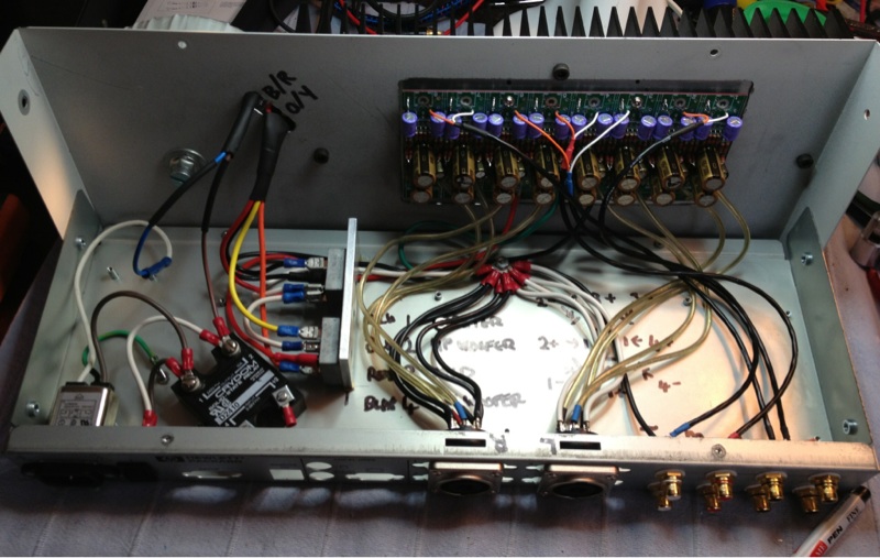
Input can be seen in the back left corner of the chassis, with the shielded input signal routed under the PCB so that it is away from the fans and the AC. There is plenty of room for metal shields if hum/buzz proves to be a problem.
Coolers exhaust vertically through pre-existing slots in the chassis (hence their centralised location on the angle) and the fans will likely be controlled by the following heat sensing control circuit to extend their life.

[Source: Elliott Sound Productions - Project 42]
This fan controller is designed to run off the positive rail of a power amplifier, up to +30VDC with component value changes. I will have +/-25VDC here.... can I just tap into this from the +V input on the PCB or will the unequal current drawn from each rail cause problems? I could add a 12V supply but I'd rather not if it's avoidable.
Any comments are be welcomed. Does it look like I have sufficient cooling? Anything glaringly wrong with the layout?
Regards,
Tani.