Re: INX5 BUILD THREAD
Posted: Mon Aug 27, 2012 7:34 am
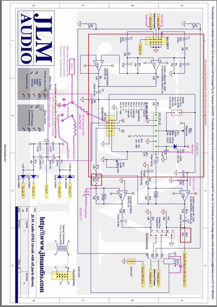
With the MAC plugged in the level should drop 6dB. Change R16 to 30k to makeup the 6dB lost by the 1:1.
Support forums for JLM Audio Kits and Products
https://www.jlmaudio.com/forum/
great.Joe Malone wrote:With the MAC plugged in the level should drop 6dB. Change R16 to 30k to makeup the 6dB lost by the 1:1.
Not really as with a output transformer the difference will change a bit depending on the input impedance of the next bit of gear in the chain.about the tiny difference between ON and standby...do you think is useful compensate it?
thanks a lot for your help!
everything clear, thanks a lot!Joe Malone wrote:Not really as with a output transformer the difference will change a bit depending on the input impedance of the next bit of gear in the chain.about the tiny difference between ON and standby...do you think is useful compensate it?
thanks a lot for your help!
But you could fit a 50k 25 turn trim pot in place of R16 so you can trim it exact in setup. (or use the 20k 25 turn trim pot in the INX5 kit in series with a 20k resistor to make R16)
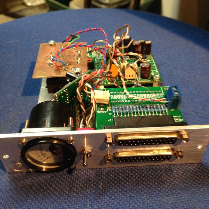
You will need to test with output transformer as DIP8 opamps like OPA2604 and NE5532 do not drive output transformers well.Bruce0 wrote:I want to use the INX5, in combination with a set of summing resistors to make a Virtual Earth/Virtual Ground (VE) active summing network. Ian Bell has a cute little TASCAM format D-Subminiature 25 pin card (DB25 summing card) over on GroupDIY. I want to try to do the following:
1) Put 2 of those DB25 Summing Cards on a 500 Series Panel.
2) Put a JLM 34mm VU meter on the panel
3) Put a Active/Passive switch on the panel. Active will mean sum to Virtual Earth (VE) amps. Passive will mean switch a shunt resistor across the summing nodes to lower the output impedance and use the relay bypass to route it to the output connector so I can optionally use a separate mic preamp to sum.
I plan to use the second stage of the INX5 using an OPA-2604 and use that as 2 separate VE inverting summing amps. Then output those amps to a transformer (one to the Primary Start (PS), and one to Primary End (PE)).
I would have done it into the first opamp so I could have a level control but your way is fine as long as the opamps can drive the output transformer properly.I had to add a second relay to disconnect the bus from the amps in passive mode (because the amp's were dragging both busses to ground! doh!). So I solved that bug, but I still have some questions:
2) Is there a better way to use the INX5 as a virtual earth summer?
Yes the transformer will sum the out of phase info and cancel any common out of phase noise etc.3) It is my impression that the way I modded the INX5 the two OPA2604 (halves) will amplify ground noise and it will be cancelled out in the primary of the transformer. Is this correct? Will it cancel?
Doesn't upset the virtual earth summer at all. Can add some noise if 0v ground has some noise on it.4) If someone plugs an UNBALANCED connection in that shorts the Cold input to ground, this will ground the bus through that summing resistor, what effect will that have. Will that screw things up too badly?
5) Am I using the right OP-AMP? Should I use the 5532? Generally I sum 6 channels. And I suppose a connected question, am I using the right summing and feedback resistors? I have chosen 6.2K summing resistors and 12.4K feedback resistors.
Only matters if you are using a transistor to switch the relay. I would switch the relay to the -v rail not 0v so there is no ground noise on switching.6) There is no protection diode on the 24V rail for surges from the relay. I put one on the rail in general to protect it, is it needed. Is one on the rail enough or do I need to strap two of them directly across the relay coils?
Sounds ok. Do some RMAA rightmark tests so you can see if the THD and IMD are ok from one input to the output.7) (Answered: I changed feedback resistors to 6.2K and summing resistors to 6.2K (16 of them for Hot, 16 for Cold) and strapped the Transformer 1:1 and it seems to work fine and the amp does not get too hot (solder the amp to the board for better cooling than the socket.). Q: Re summing and feedback resistors.
Your use of opamps backwards had me confused to start withstudiomollan wrote:Hi
I'm considering the inx5 as the backbone of a basic channel strip for an upgrade to my console. It's a vintage API 2488 and the original 24 input tape monitor mixer is ripped out. The original tape returns are not really anything worth reproducing and a lot of the functions are not really needed in the pro tools world of today.
I'm thinking of building them in the 500 series format instead of the original half wide, double length format.
So:
24 input channels with 4 aux sends on two pots, one switch for either 1/3 or 3/4 plus a global pre/post for the auxes. Fader, pan, mute, solo and transformer balanced direct out.
As input I'm considering a Harrison ford filter module. That will serve as the line input and the output will be an insert send. The balanced input of the inx5 will be the insert return. The unbalanced loop of the inx5 will first feed the pre fader aux send, then fader. The pin 11 output of the inx5 (radial mixer out) will feed the post fader aux send, pan pot, solo bus, and then out to the stereo buses. The balanced output will serve as a direct out via Ed Anderson 2623, 1:2, transformers. The bypas relay will be changed to mute the output, channel on switch.
All of the buses will be connected to the original buses.
I would like to use the 5534 op amps on the inx5 to keep the labour and cost down.
What value should I use for the aux pots and fader? (I have LOTS of 10kA high quality pots) Where would you connect the relay, mute circuit, and how? I would like to be able to mute the channel but still be able to use the pre fader sends. Any pros/cons with doa or dip8 op-amps. I read in a earlier post that the dip8 doesn't drive transformers very well?
I would be very glad for any input on this.
/
Emil
Hi Joe and Thanks fot your answer!Joe Malone wrote:Your use of opamps backwards had me confused to start withstudiomollan wrote:Hi
I'm considering the inx5 as the backbone of a basic channel strip for an upgrade to my console. It's a vintage API 2488 and the original 24 input tape monitor mixer is ripped out. The original tape returns are not really anything worth reproducing and a lot of the functions are not really needed in the pro tools world of today.
I'm thinking of building them in the 500 series format instead of the original half wide, double length format.
So:
24 input channels with 4 aux sends on two pots, one switch for either 1/3 or 3/4 plus a global pre/post for the auxes. Fader, pan, mute, solo and transformer balanced direct out.
As input I'm considering a Harrison ford filter module. That will serve as the line input and the output will be an insert send. The balanced input of the inx5 will be the insert return. The unbalanced loop of the inx5 will first feed the pre fader aux send, then fader. The pin 11 output of the inx5 (radial mixer out) will feed the post fader aux send, pan pot, solo bus, and then out to the stereo buses. The balanced output will serve as a direct out via Ed Anderson 2623, 1:2, transformers. The bypas relay will be changed to mute the output, channel on switch.
All of the buses will be connected to the original buses.
I would like to use the 5534 op amps on the inx5 to keep the labour and cost down.
What value should I use for the aux pots and fader? (I have LOTS of 10kA high quality pots) Where would you connect the relay, mute circuit, and how? I would like to be able to mute the channel but still be able to use the pre fader sends. Any pros/cons with doa or dip8 op-amps. I read in a earlier post that the dip8 doesn't drive transformers very well?
I would be very glad for any input on this.
/
Emil. But yes this would work perfectly on the INX5 pcb. Don't forget to add series resistors between all pot wiper and solo switch to the buss connections. To run the output transformer you should use a DOA in the second opamp (look at using our V8 DOA with 4 x NE5532AP as it will keep costs down and can drive anything). Other wise DIP8 will work fine as the input first opamp. NE5532AP can drive 300R on INX5 as it uses both halves in parallel so 1k fader with parallel auxs etc will work fine. Just make the 4k7 feeding the radial mix out a 0R link and it will work fine. Cutting 2 pins off the bypass relay will turn in into the channel on that you want.
Let me know if you need any more info. Email me some quantities when you are ready and I will setup some quantity discounts on the webshop before you order.
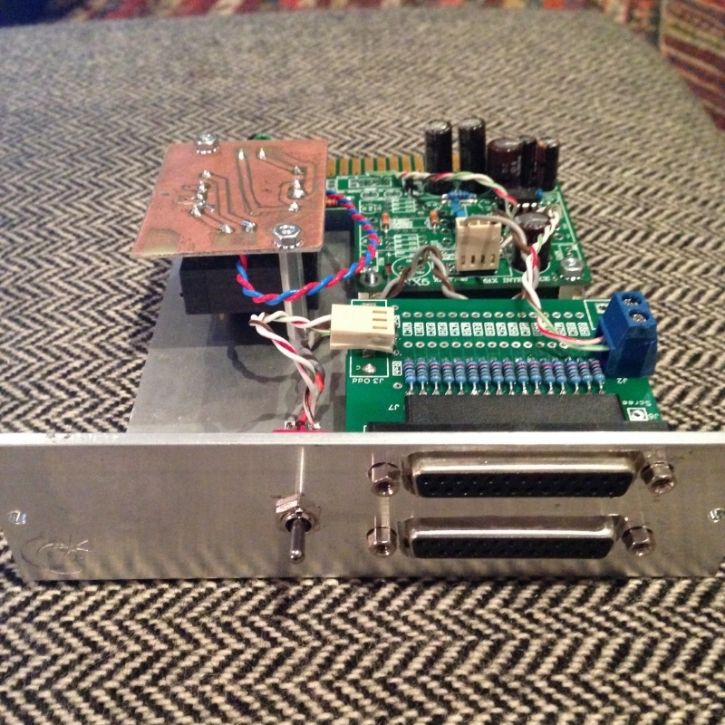
(edit: read through the Dingo thread and here's my conclusions)Joe Malone wrote:Under ConstructionINX5 + JLM GO between PLUS kit makes a 51X or 500 series Mic preamplifier
Sorry missed this somehow.frans wrote:(edit: read through the Dingo thread and here's my conclusions)Joe Malone wrote:Under ConstructionINX5 + JLM GO between PLUS kit makes a 51X or 500 series Mic preamplifier
My MK-U47 condenser mic (ioaudio, groupdiy) has - like so many condenser mics and some moving coil mics close to a loud source - a really high level output. My dear JLM99*MB mic preamps can only cope with that with the pad engaged. So, not hesitating to find an excuse to build more JLM gearwhy shouldn't i build an insane mic level INX5? Input transformerless (OPA2604 for balancing?), changing the 20k resistors before the debalancing stage to 10k to have an additional safety buffer of -6dB. No mic in the world would clip that input, right? Output some JLM flavour or some the Melcor 1731 I got in the drawer, feeding a 1:2 Pikatron, which can take 24dBu without sweating.
-do you got a spare steel bracket like the one in the first post in this thread, Joe? Didn't see them in the shop.
-of course a blank 500 panel
-input Z ...hm..hm... Don't got the schematic in my head right now but I think it can be adapted within a reasonable range...? Thinking about a lot of my gear has 50 or 100 ohms output Z.. which has no problems going into a 10k or 20k input of some outboard or the A/D. Anything against the ca. 200r output Z going into a 20k input? I've read that for example the Shure SM57 doesn't like too high preamp impedance, as the transformer in the mic will ring(?) which wouldn't bother me, as I never use a 57 in the studio, for snare top I more likely grab a Heil PR20 (output Z 600r) because .. I like it. Better hihat rejection and a few other things. For example, the Gordon preamp sports an input Z of 1-2 megaohms. Phew.
-gain - 34dB with the balancing stage.. should be well enough.
Throw in a phase reverse switch on the front panel (a GoBetween where I just use the phase and skip the 48v/pad would be a sad waste, huh?)
What else to take into account? I already got a good number of nice preamps, so tailoring this one as a one trick pony especially for mics that don't need phantom (tube mics, moving coil) and have massive output doesn't seem to crazy.... at least to me.
I guess I could make it workJoe Malone wrote:This thread when finished became the BA500 and LA500 threads. Both units share the same bracket so best to look at there build threads to see if that bracket would work for you. But it needs a meter to hold together properly.
Okay - re-read this and checked it against the schematic, I think I understand, it's R3+5 (now 20k) which should go down to 2k to make the situation less noisy. What about R4+6 - i wanted them at 10k to have that stage more headroom (reading through the Dingo thread) - but I'm not fluent enough with electronics to see through the implications of having R3+5 down at 2k now. As I'm relieved I got my MK-U47 working on first try... and not wanting to drill a hole for a switch or permanetly 'fix' the mic with a small condenser across the capsule...I'll better leave that. IMHO a condenser shouldn't be on anything louder than a loud voice (which can get pretty loudJoe Malone wrote:Feeding a mic into a series resistor feed balanced in is not a good idea as it makes the signal to noise much worse than a direct no series resistance input like in most mic pres use. The noise problem can be made better by lowering the resistor values a lot like 20k to 2k and 10k to 1k.
Sounds like an idea - if the JLM14 takes these input levels...? Or maybe I could use another inputX....cable ties...1:1 input...? Duh, which input transformer can take it?Joe Malone wrote:But if you wanted a 500 mic pre to do what you want. Use a BA500 kit which has minimum gain of 21dB with no pad and change the gain pot to a 12 position switch with open circuit at the lowest setting so minimum gain is 13dB no pad.
Drop me a note when pre-orders are taken...Joe Malone wrote:Otherwise I am slowly working on changing our BAN into a 500 mic pre which is the perfect way to do what you describe with the INX5 but with very low noise input.
