MONO Ver2 Mic pre kit BUILD THREAD
Posted: Wed Apr 27, 2011 5:36 pm
JLM MONO Ver2 mic pre is a compact tough transformer balanced input mic pre with electronic balanced output which can run on 2 x 9v Normal Alkaline or Rechargeable NiMH batteries and provide 18v phantom power which will run most modern condenser microphones or you can use our 48v 520mA SMPS which can charge NiMH batteries at the same time as running the mic pre with 48v phantom power and greater headroom. One 48v SMPS can run and charge 8 MONO Mic pres easy. As usual the same large variety of input transformers can be used as Baby Animal and Baby Animal Dual. The pre is made to run one Dual NE5532AP on 18v battery power up to 27v with zener reg fitted or OPA2604AP opamp on 18v battery power up to 48v SMPS power but can have 2 x JLM99v and compatible footprint discrete opamps fitted with no component changes but the battery power option is then lost. Kit comes with a full laser cut die-cast aluminum box and black lexan text front panel top.

Internal single sided PCB fitted with components for electronic training version for JMC Academy and TAFE Colleges.
Parts List MONO Training Version
MONOv2 Schematic
MONO Upgrade options on JLM web shop
(Main upgrade the training version needs is the input transformer to get a real top end mic pre & 48v SMPS for true 48v phantom power and +28dBM huge output level)
JLM14 Input transformer (Great for drums, bass, samples and general very good all rounder)
OEP262A3C/VTX Input transformer (Great Vocals, Acoustic Instruments. Bit more coloured as used in our Dual99v mic pre)
JLM99v discrete opamp (Fatter low end and silky high end then OPA or Hybrid)
6 Sockets to plug in JLM99v etc
48v SMPS power supply (Can run & charge 8 x MONO mic pre at one time)
2 x 9v NiMH batteries
1. Install all resistors in there correct locations using chart to the left or better still by using a multimeter with no leads fitted and bending the legs of the resistor and putting them in the meter sockets to double check you have the right value before putting it into the PCB.
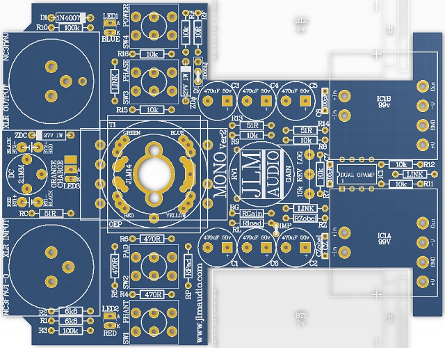
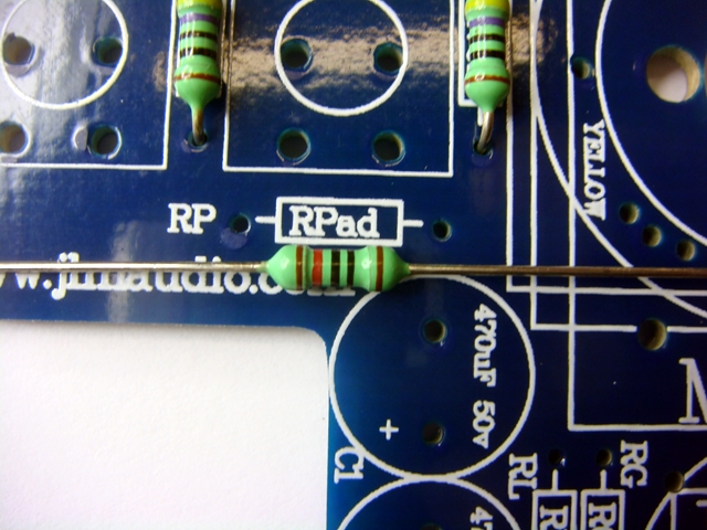
Red Transformer Training Version RPad = 120R, RGain = 22R Rload = Not Fitted, RZobel = LINK, Czobel = 390pF.
(If you are thinking of upgrading your college version later to one of the better transformer versions below it is fine to fit the below values now with the Red transformer. Rload will not affect the red transformer and the larger Rgain will just give less gain until the upgraded transformer is fitted.
JLM14 Transformer fitted fitted to Training Version MONO RPad = 120R, RGain = 68R Rload = 10k, RZobel = LINK, Czobel = 390pF.
JLM14 Transformer fitted fitted to Normal Version MONO RPad = 120R, RGain = 68R Rload = 2k2, RZobel = LINK, Czobel = 390pF. Impedance pot 50k log
[/b][/color]OEP 262A3C / VTX Transformer fitted to Training Version MONO RPad = 120R, RGain = 68R Rload = 27k, RZobel = LINK, Czobel = 390pF.
OEP 262A3C / VTX Transformer fitted to Normal Version MONO RPad = 120R, RGain = 68R Rload = 10k, RZobel = LINK, Czobel = 390pF. Impedance pot 100k log
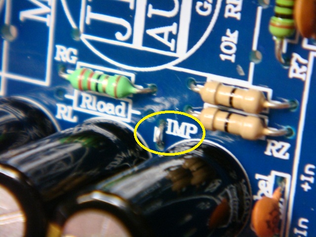
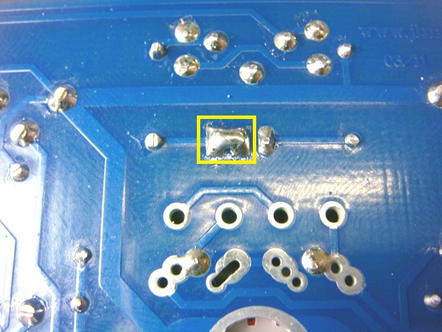
(The MONO PCB has a impedance pot option which is not used in the Training kits so when fitting RLoad the small white line between 2 holes at one end of RLoad needs to be jumper over with a resistor leg cut off. See near bottom of this post)
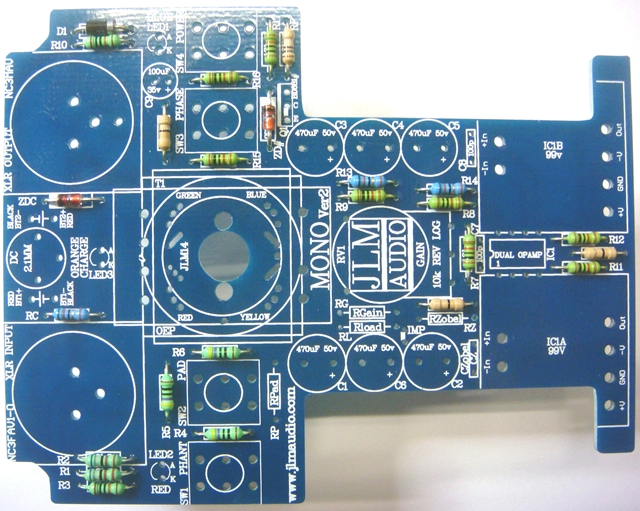
1.Fit all resistors before soldering them as this can also help check that you haven't put a resistor in the wrong place.
2. Install all diodes with there Grey/White/Black strip band lining up white white band on the PCB.
RC can be either 47R or 51R. Kit may have 3 x 51R or 2 x 51R + 1 x 47R
27v zeners maybe red or silver type but check number on zener is 1N4750 or 1N4750A
RPad 120R can be mistaken for a 10k if the code is read from the wrong end.
The colour stripe spaced wider apart then the rest of the stripes is always the tolerance stripe and should be kept to the right hand side while reading the colour code value.
RGain is 22R in training version with red transformer and 68R with JLM14 & OEP/VTX transformers.
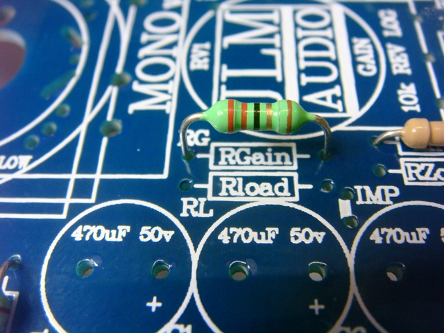
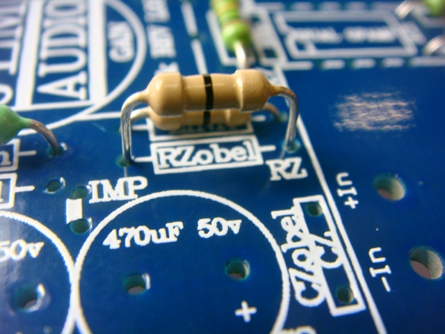
RZobel is a zero ohm link resistor for all normal MONOv2 configurations
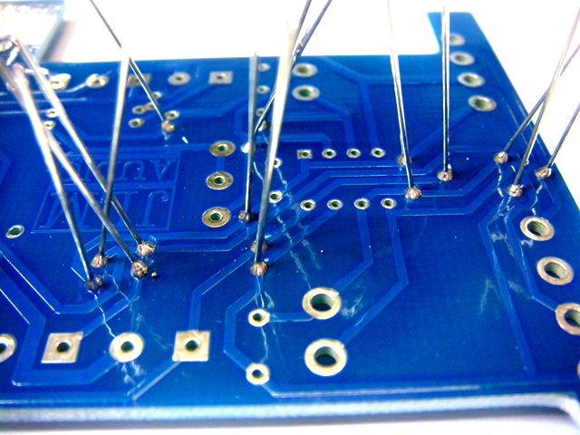
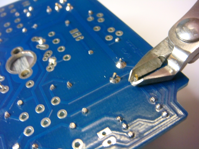
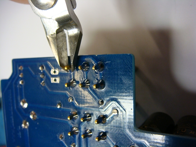
3. Once all resistors and diodes are fitted solder them in with the PCB held upside down on a flat surface and then cut there legs just flush above the solder joint.
Use one of the cut off resistor legs for the IMP link and solder in then cut there legs just flush above the solder joint.
Note if installing variable impedance Z control fit 2 wires here instead
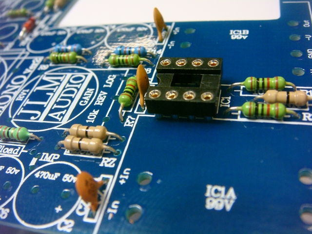
4. Fit IC Socket with the U aligned with the overlay and solder in. Then fit R7 & R8 the 2 x 100pF caps either way around. And CZobel 390pF cap.
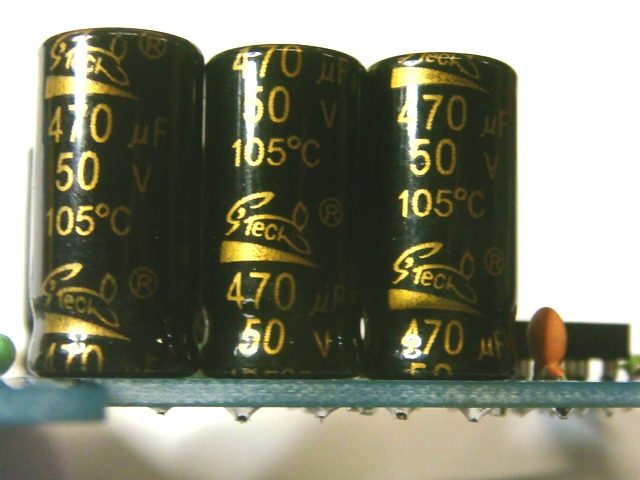
5. Place the 1 x 100uF and 6 x 470uF caps on the PCB with there long leg fitted in the hole marked + which is a square pad under the PCB.

6. Solder in all 7 caps which should all be facing the same direction when finished.
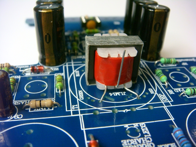
7. Fit transformer to the PCB. No gap needs to be left for any of the transformers as the PCB is single sided. Red transformer shown below. JLM14 bolts to PCB and the four colours of its wires are marked on the top of the PCB. Black is not connected to anything. JLM14 wires go into large centre hole and solder under the PCB. OEP transformer only fits one way on the PCB making it easy.
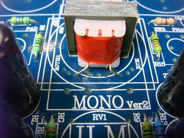
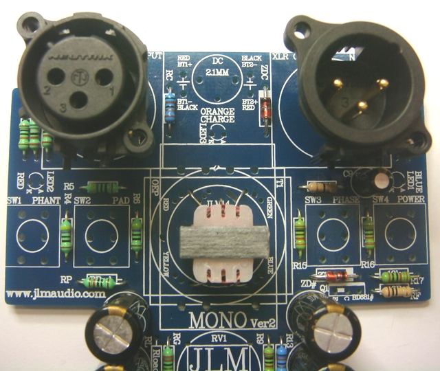
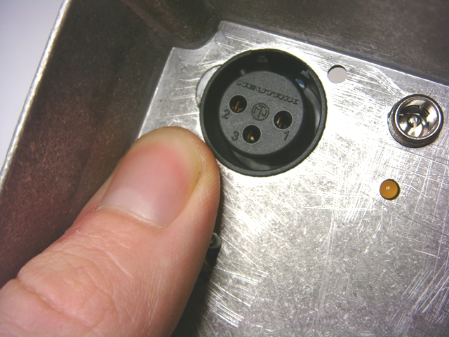
8. Solder in the transformer wires and then fit the XLR's and solder them in.
9. Push in all toggles with there U notch away from the XLR's. Make sure they are sitting flat and level to the PCB.
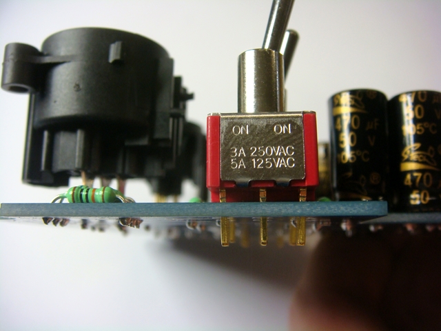
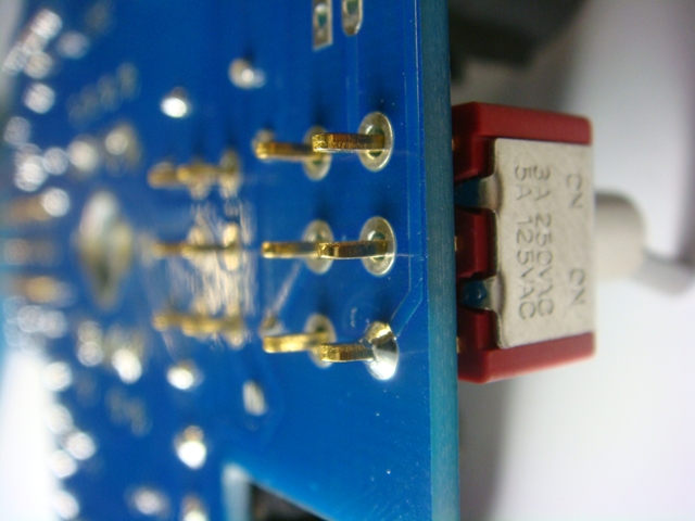
10. With the XLR's fitted you can do a test fit into the case and check the 4 toggles switch up & down in there slots ok with only one centre pad soldered encase the toggle needs to be moved slightly before soldering all the switch legs.
(Watch out when cutting of soldered legs that they are actually soldered otherwise they can be hard to fault find later)
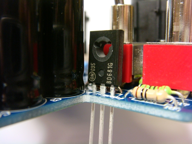
11. Fit BD681 transistor as shown and solder in.
Note if installing JLM99v opamps no NOT fit BD681. Instead fit link wire between C & E as PCB overlay shows
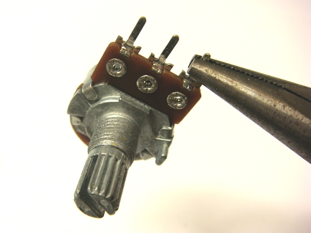
12. Use long nose pliers to bend the 3 pot legs 90 degrees.
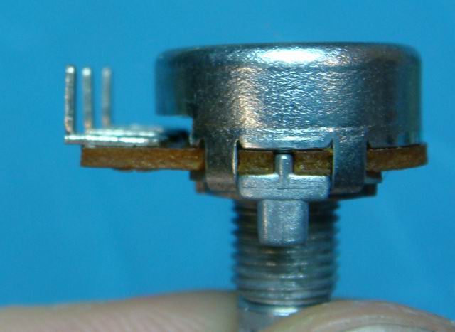
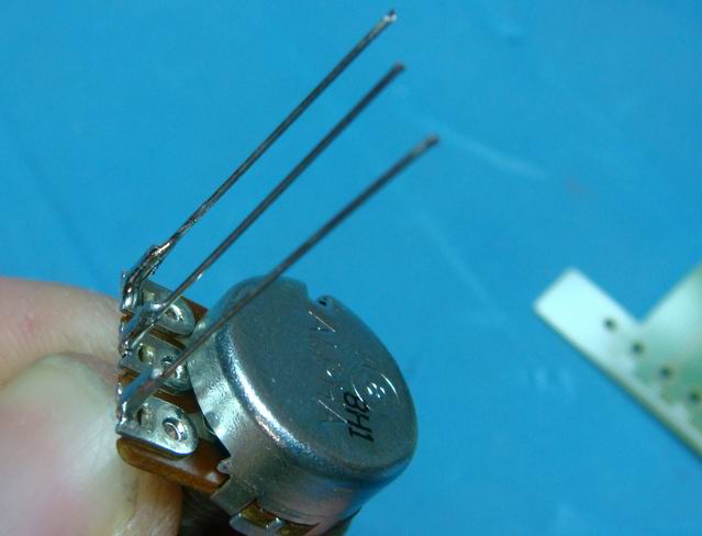
13. Extend the legs by using the full leg length from the two spare zero ohm links in the kit.
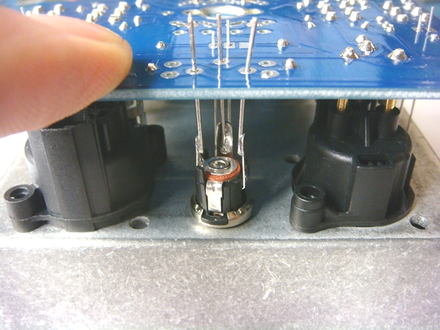
14. Extend the DC connector legs with 3 cut off zener diode legs as shown. The zener diode legs are thicker and stiffer than the resistor legs.
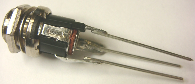
15. The DC connector fits into the PCB with its 3 legs going directly into PCB as shown.
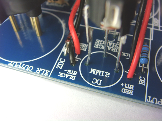
16. The 3 LED's are placed into the positions long leg to A. Do not swap the LED colors around at all as this will affect the charge circuit.
(Placing your thumb over the LED hole while bending the LED legs sticking out of the solder side outwards from each other slightly will allow the led to hang at the right height ready for soldering)
You want the led in the hole but not sticking out the other side of the hole as the lexan panel cover the hole with a frosted lens.
17. LED's in position but will not be soldered until fitted to the case with the gain pot to get the right height.

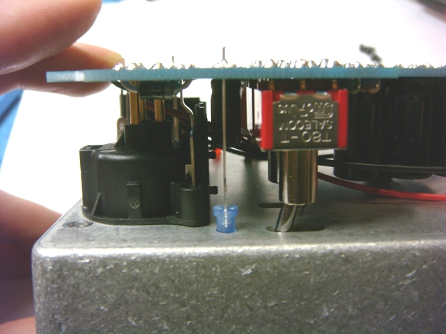
18. PCB placed upside down on top of the case to get lengths right and then DC connector and 3 LEDs can all be soldered.

The PCB can then be test fitted inside the case go the Gain pot height can be set and soldered in place.
(This cannot be done outside of case as pot keyway will stop the pot going into position correctly.)
19.Fitting the Battery leads. Note positive and negative are reversed on each side.
20. Leave these solder pads unsoldered for normal 9v batteries.
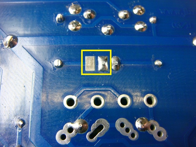
Only solder together when using rechargeable NiMH batteries.
(Soldering together enables charger and orange charge LED)
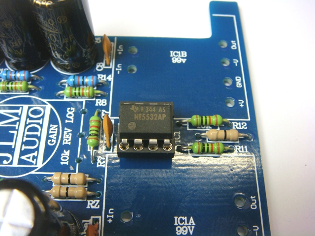
21. Fit NE5532AP IC into the DIP socket with its U aligned with the IC socket upwards as shown below.
Ready to test in the open with 2 x 9v batteries or 48v SMPS.
If testing without batteries fitted put some tape on the 9v clips to stop them shorting to anything.
Please make sure you have your monitors or headphones turned down when power on or off on the MONO mic pre to save your ears
Note you can only fit IC1 DIP8 opamp like NE5532AP or IC1A,IC1B large JLM99v opamps. Do NOT fit both types at once.
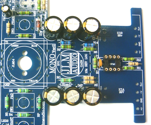
22. MONO training version PCB fully built.
23. Shows the stick on black rubber strip for holding in the 9v batteries firmly.

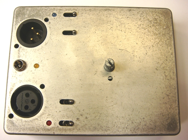
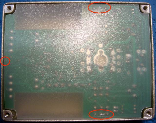
24. Shows plastic protective sheet used to stop the 3 points in red circles from touching the lip of the diecast bottom panel.
Make sure all soldered pad joints especially the ones in the red circles are cut short and the plastic sheet need to be a tight fit in the back of the case.
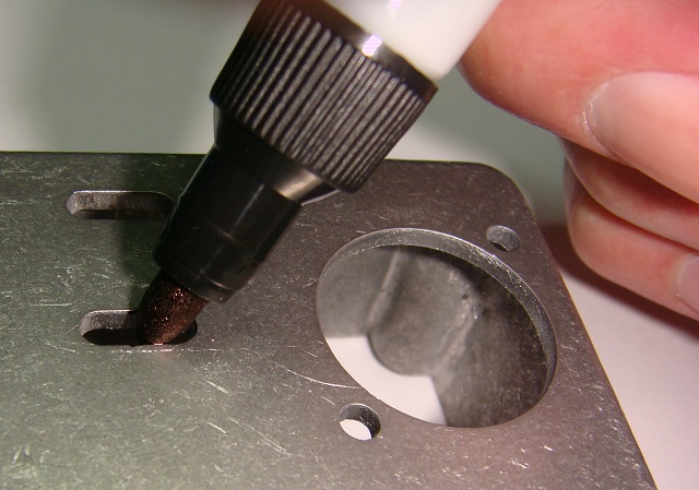
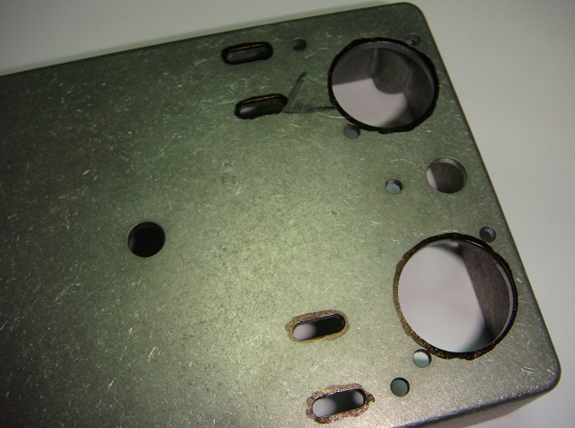
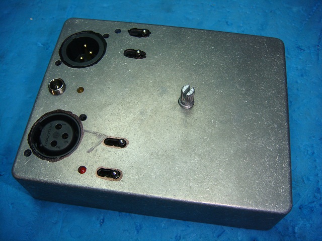
25. Black edge of slots and XLR holes with black permanent pen to remove shine from edges.
26. Fit PCB to case and do a test fit of the lexan panel before removing the backing to check best alignment.
27. Remove sticker backing

28. Flex lexan panel so it can be aligned by the DC and Gain pot holes.
Sticker can be removed if not pressed hard down on.
(Sticker can be fitted with the case empty or with the PCB fitted so DC connector and Gain pot can help to align the sticker)
(Note sticker holes for DC connector and Gain pot are 0.5mm larger so the sticker can still be moved around slightly for better overall alignment)
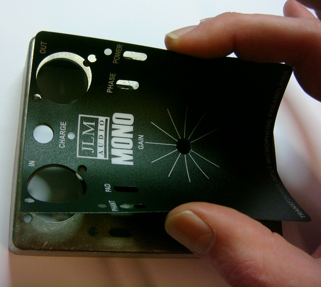
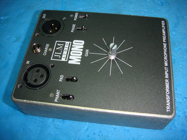
29. alignment is correct the sticker can be pressed down hard from the center out.
After about 24 to 48 hours the glue on the sticker will bond with the case making it very hard to remove.
End of Training version
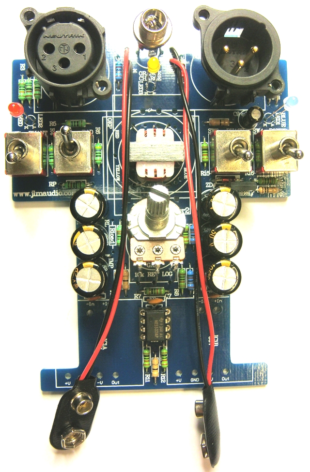
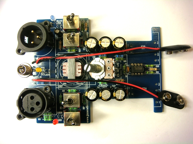
Z pot wiring on MONO normal version.
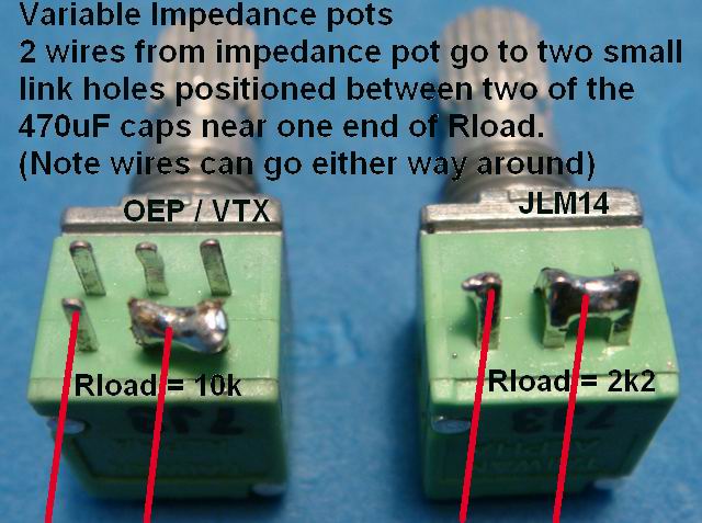
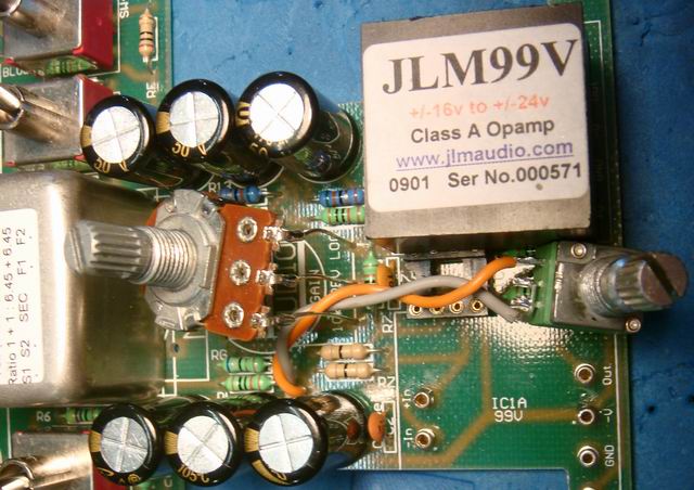
Shows Z pot wiring and MONO with 2 x 99v Fitted.
NOTE When fitting JLM99V to MONO do NOT fit C7 or C8 100pF caps as we have found this makes the MONO pre more stable and less prone to oscillation when using the 99V
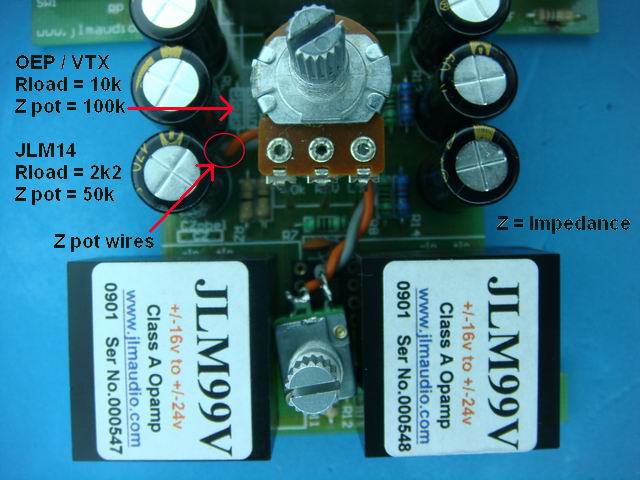
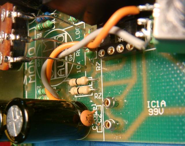
For Z pot wiring do NOT fit this jumper. Wire the two Z pot wires to here instead.
Note first 99v opamp removed only to show wiring better
Note first 99v opamp removed only to show wiring better
Internal single sided PCB fitted with components for electronic training version for JMC Academy and TAFE Colleges.
Parts List MONO Training Version
MONOv2 Schematic
MONO Upgrade options on JLM web shop
(Main upgrade the training version needs is the input transformer to get a real top end mic pre & 48v SMPS for true 48v phantom power and +28dBM huge output level)
JLM14 Input transformer (Great for drums, bass, samples and general very good all rounder)
OEP262A3C/VTX Input transformer (Great Vocals, Acoustic Instruments. Bit more coloured as used in our Dual99v mic pre)
JLM99v discrete opamp (Fatter low end and silky high end then OPA or Hybrid)
6 Sockets to plug in JLM99v etc
48v SMPS power supply (Can run & charge 8 x MONO mic pre at one time)
2 x 9v NiMH batteries
1. Install all resistors in there correct locations using chart to the left or better still by using a multimeter with no leads fitted and bending the legs of the resistor and putting them in the meter sockets to double check you have the right value before putting it into the PCB.
Red Transformer Training Version RPad = 120R, RGain = 22R Rload = Not Fitted, RZobel = LINK, Czobel = 390pF.
(If you are thinking of upgrading your college version later to one of the better transformer versions below it is fine to fit the below values now with the Red transformer. Rload will not affect the red transformer and the larger Rgain will just give less gain until the upgraded transformer is fitted.
JLM14 Transformer fitted fitted to Training Version MONO RPad = 120R, RGain = 68R Rload = 10k, RZobel = LINK, Czobel = 390pF.
JLM14 Transformer fitted fitted to Normal Version MONO RPad = 120R, RGain = 68R Rload = 2k2, RZobel = LINK, Czobel = 390pF. Impedance pot 50k log
[/b][/color]OEP 262A3C / VTX Transformer fitted to Training Version MONO RPad = 120R, RGain = 68R Rload = 27k, RZobel = LINK, Czobel = 390pF.
OEP 262A3C / VTX Transformer fitted to Normal Version MONO RPad = 120R, RGain = 68R Rload = 10k, RZobel = LINK, Czobel = 390pF. Impedance pot 100k log
(The MONO PCB has a impedance pot option which is not used in the Training kits so when fitting RLoad the small white line between 2 holes at one end of RLoad needs to be jumper over with a resistor leg cut off. See near bottom of this post)
1.Fit all resistors before soldering them as this can also help check that you haven't put a resistor in the wrong place.
2. Install all diodes with there Grey/White/Black strip band lining up white white band on the PCB.
RC can be either 47R or 51R. Kit may have 3 x 51R or 2 x 51R + 1 x 47R
27v zeners maybe red or silver type but check number on zener is 1N4750 or 1N4750A
RPad 120R can be mistaken for a 10k if the code is read from the wrong end.
The colour stripe spaced wider apart then the rest of the stripes is always the tolerance stripe and should be kept to the right hand side while reading the colour code value.
RGain is 22R in training version with red transformer and 68R with JLM14 & OEP/VTX transformers.
RZobel is a zero ohm link resistor for all normal MONOv2 configurations
3. Once all resistors and diodes are fitted solder them in with the PCB held upside down on a flat surface and then cut there legs just flush above the solder joint.
Use one of the cut off resistor legs for the IMP link and solder in then cut there legs just flush above the solder joint.
Note if installing variable impedance Z control fit 2 wires here instead
4. Fit IC Socket with the U aligned with the overlay and solder in. Then fit R7 & R8 the 2 x 100pF caps either way around. And CZobel 390pF cap.
5. Place the 1 x 100uF and 6 x 470uF caps on the PCB with there long leg fitted in the hole marked + which is a square pad under the PCB.
6. Solder in all 7 caps which should all be facing the same direction when finished.
7. Fit transformer to the PCB. No gap needs to be left for any of the transformers as the PCB is single sided. Red transformer shown below. JLM14 bolts to PCB and the four colours of its wires are marked on the top of the PCB. Black is not connected to anything. JLM14 wires go into large centre hole and solder under the PCB. OEP transformer only fits one way on the PCB making it easy.
8. Solder in the transformer wires and then fit the XLR's and solder them in.
9. Push in all toggles with there U notch away from the XLR's. Make sure they are sitting flat and level to the PCB.
10. With the XLR's fitted you can do a test fit into the case and check the 4 toggles switch up & down in there slots ok with only one centre pad soldered encase the toggle needs to be moved slightly before soldering all the switch legs.
(Watch out when cutting of soldered legs that they are actually soldered otherwise they can be hard to fault find later)
11. Fit BD681 transistor as shown and solder in.
Note if installing JLM99v opamps no NOT fit BD681. Instead fit link wire between C & E as PCB overlay shows
12. Use long nose pliers to bend the 3 pot legs 90 degrees.
13. Extend the legs by using the full leg length from the two spare zero ohm links in the kit.
14. Extend the DC connector legs with 3 cut off zener diode legs as shown. The zener diode legs are thicker and stiffer than the resistor legs.
15. The DC connector fits into the PCB with its 3 legs going directly into PCB as shown.
16. The 3 LED's are placed into the positions long leg to A. Do not swap the LED colors around at all as this will affect the charge circuit.
(Placing your thumb over the LED hole while bending the LED legs sticking out of the solder side outwards from each other slightly will allow the led to hang at the right height ready for soldering)
You want the led in the hole but not sticking out the other side of the hole as the lexan panel cover the hole with a frosted lens.
17. LED's in position but will not be soldered until fitted to the case with the gain pot to get the right height.
18. PCB placed upside down on top of the case to get lengths right and then DC connector and 3 LEDs can all be soldered.
The PCB can then be test fitted inside the case go the Gain pot height can be set and soldered in place.
(This cannot be done outside of case as pot keyway will stop the pot going into position correctly.)
19.Fitting the Battery leads. Note positive and negative are reversed on each side.
20. Leave these solder pads unsoldered for normal 9v batteries.
Only solder together when using rechargeable NiMH batteries.
(Soldering together enables charger and orange charge LED)
21. Fit NE5532AP IC into the DIP socket with its U aligned with the IC socket upwards as shown below.
Ready to test in the open with 2 x 9v batteries or 48v SMPS.
If testing without batteries fitted put some tape on the 9v clips to stop them shorting to anything.
Please make sure you have your monitors or headphones turned down when power on or off on the MONO mic pre to save your ears
Note you can only fit IC1 DIP8 opamp like NE5532AP or IC1A,IC1B large JLM99v opamps. Do NOT fit both types at once.
22. MONO training version PCB fully built.
23. Shows the stick on black rubber strip for holding in the 9v batteries firmly.
24. Shows plastic protective sheet used to stop the 3 points in red circles from touching the lip of the diecast bottom panel.
Make sure all soldered pad joints especially the ones in the red circles are cut short and the plastic sheet need to be a tight fit in the back of the case.
25. Black edge of slots and XLR holes with black permanent pen to remove shine from edges.
26. Fit PCB to case and do a test fit of the lexan panel before removing the backing to check best alignment.
27. Remove sticker backing
28. Flex lexan panel so it can be aligned by the DC and Gain pot holes.
Sticker can be removed if not pressed hard down on.
(Sticker can be fitted with the case empty or with the PCB fitted so DC connector and Gain pot can help to align the sticker)
(Note sticker holes for DC connector and Gain pot are 0.5mm larger so the sticker can still be moved around slightly for better overall alignment)
29. alignment is correct the sticker can be pressed down hard from the center out.
After about 24 to 48 hours the glue on the sticker will bond with the case making it very hard to remove.
End of Training version
Z pot wiring on MONO normal version.
Shows Z pot wiring and MONO with 2 x 99v Fitted.
NOTE When fitting JLM99V to MONO do NOT fit C7 or C8 100pF caps as we have found this makes the MONO pre more stable and less prone to oscillation when using the 99V
For Z pot wiring do NOT fit this jumper. Wire the two Z pot wires to here instead.
Note first 99v opamp removed only to show wiring better
Note first 99v opamp removed only to show wiring better


