AMP HEAD Build Thread
Posted: Sat Feb 26, 2011 3:28 pm
AMP HEAD
Small but extremely powerful stereo headphone amp kit with balanced inputs, buss connector, volume control.
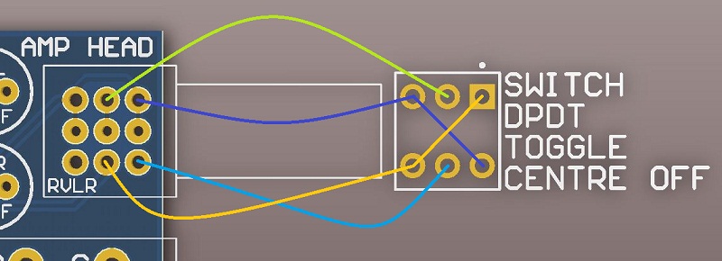
Mono and mute options can be added with one center off toggle switch and no other parts wired across the 4 outside pot terminals. (I will do a drawing of this ASAP)
Several AMP Head's can be power and audio connected with one 10 wire IDC ribbon cable.
Can sum several balanced inputs into AMP HEAD with 10k resistors. (I will do a drawing of this ASAP)
Can handle full overload into short circuit permanently.
Can drive 8 to 600ohm headphones easily.
Frequency response 0, -1dB = 5Hz to 200kHz (or 5Hz to 50kHz if 220pF caps added under PCB across R7 and R8)
THD = 0.006% until onset of clipping.
Idle current = 50mA per AMP HEAD kit.
Max current = 90mA per AMP HEAD kit.
Can be powered by symmetrical +/-12v to +/-24v power rails.
Can also be powered by single 12v to 48v power rail as long as 2 zeners rated at half the voltage used are fitted to the PCB.
(for example 2 x 24v zeners fitted to make +/-24v from one of our 48v SMPS supplies. Any DC connector must be isolated type.)
+/-6v to +/-18v for NE5532AP and most dual type opamps. (Will work with lots of dual opamp type BUT they must be able to drive a 600ohm load.)
+/-12v to +/-24v can be used with OPA2604AP.
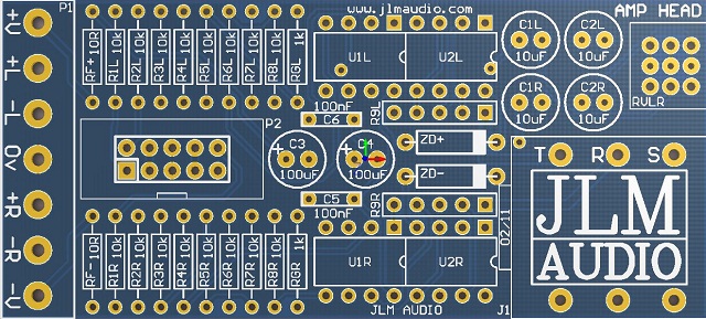
AMP HEAD PCB. Size 3.1" (87.75mm) x 1.4" (35.55mm)
AMP HEAD Parts list
1 x AMP HEAD PCB
1 x Cliff S4 6.3mm Socket
1 x Cliff S4 6.3mm Chrome nut
1 x Cliff S4 6.3mm plastic dress trim
2 x Cliff S4 6.3mm Fiber washer
2 x DIP16 machined pin socket
1 x 10pin IDC header
1 x 3 way terminal block
2 x 2 way terminal block
2 x 100uF 25v electro cap
4 x 10uF 25v Bi Polar electro cap
2 x 100nF mono cap or 1uF mono cap
1 x Dual 10k 9mm log pot
1 x pot washer
1 x pot nut
2 x 470R 5pin SIL Buss resistor packs
2 x 10R carbon 1/4 watt resistor
2 x 1k Metal film 1/4 watt resistor
16 x 10k Metal film 1/4 watt resistor
Options
4 x NE5532AP or OPA2604AP or None
2 x 1watt zener diodes which are only needed in special setups and not included in the kit.
Extra 100nF decoupling caps can be mounted in the ZD+ & ZD- positions if zeners are not used.
If fitting zeners the 2 x 10R RF+ and RF-may need to change value depending on zener diode voltage and +/-V.
Direct links to cad, corel and pdf files
http://www.jlmaudio.com/AMP%20HEAD/AMP% ... %20OUT.dxf
http://www.jlmaudio.com/AMP%20HEAD/AMP% ... %20OUT.cdr
http://www.jlmaudio.com/AMP%20HEAD/AMP% ... %20OUT.pdf
AMP HEAD BUILD
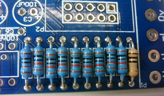
As always fit all parts with value shown on the PCB from the lowest to the highest height parts.
Fit all resistors to the PCB in one go and then solder them in.
Add zeners now if you are using a single rail like our 48v SMPS (eg. 2 x 24v 1w).
To form resistor or zener legs hold resistor body between thumb and finger and run other hand past to bend the legs to 90degrees.
If unsure of resistor color codes push resistor now into multimeter terminals (without test leads fitted) to check resistor value before placing into PCB.
Solder in IC sockets flush to PCB
(Kits comes with 2 x 16pin sockets instead to make fitting easier)
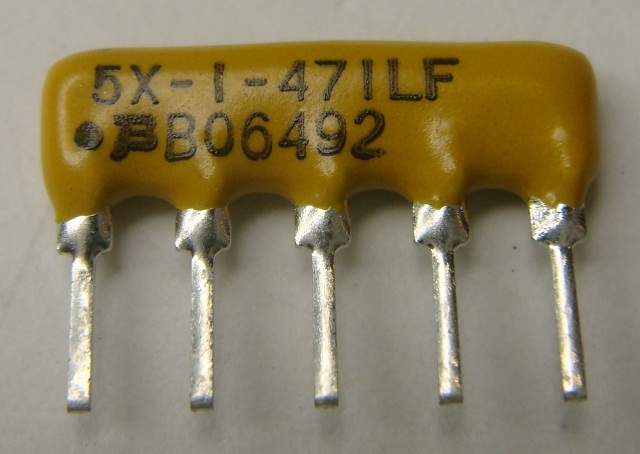
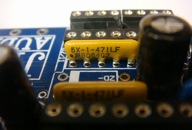
Fit 470R SIP resistor packs.
(Pin with black dot above must go into the square pad as shown)
Fit 2 x blue or yellow 0.1uF mono caps (new kits have 1uF which look identical. Either works fine)
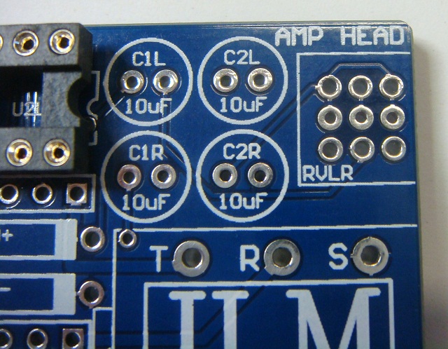
and 4 x 10uF Bi Polar caps either way around.
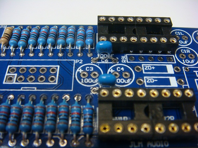
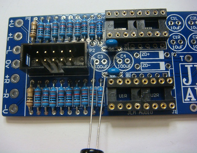
Fit 2 x 100uF caps with positive long leg into pad marked with +
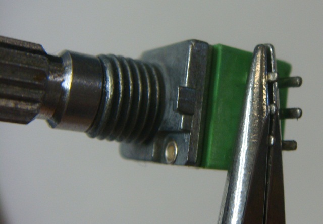
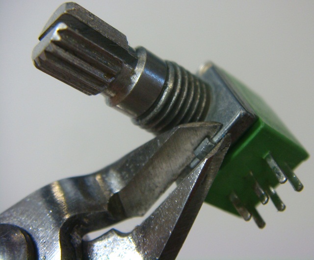
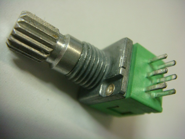
Straighten legs of pot with long nose pliers and cut off locate tab with side cutters.
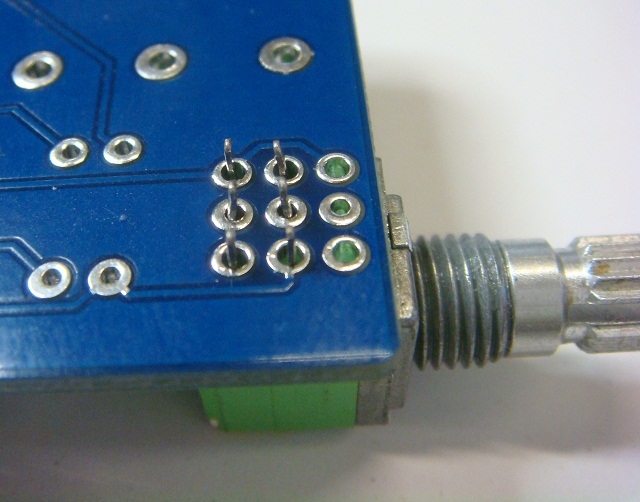
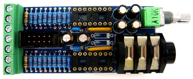
The pot can mount in two offset positions on the PCB to allow for different thickness front panels and different jack types.
Pot shown in back position for S2 plastic nut type jacks.
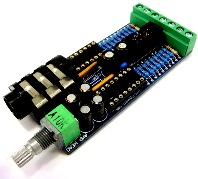
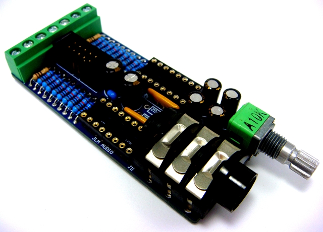
Mount in the front position for S4 chrome nut type jacks as supplied with the kit.
This will push the pot forward so it will bolt up to a 3mm front panel in alignment with the S4 jack with one fibre washer fitted.
For thinner panels fit extra washer to pot and S4 socket. Recommend NOT soldering the pot until you test against the front panel.
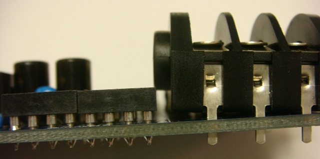
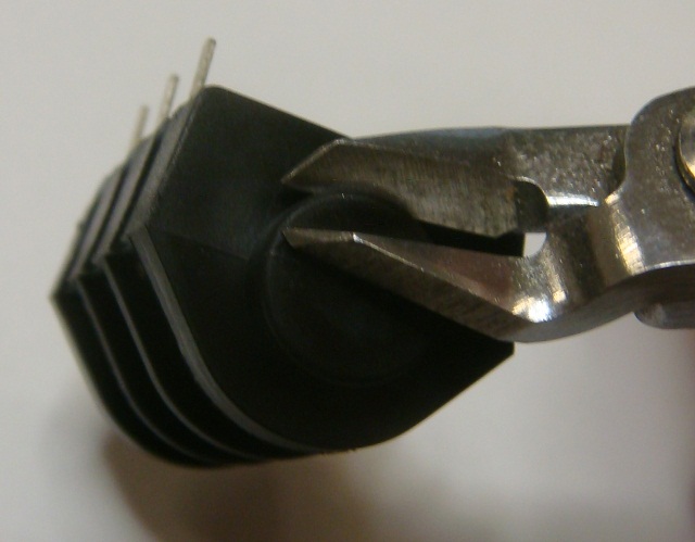
The IC socket and jack clash slightly so a small piece needs to be removed with side cutters form the back of the jack.
Finished AMP HEAD ready for 4 x Dual opamps to be fitted.
Small but extremely powerful stereo headphone amp kit with balanced inputs, buss connector, volume control.
Mono and mute options can be added with one center off toggle switch and no other parts wired across the 4 outside pot terminals. (I will do a drawing of this ASAP)
Several AMP Head's can be power and audio connected with one 10 wire IDC ribbon cable.
Can sum several balanced inputs into AMP HEAD with 10k resistors. (I will do a drawing of this ASAP)
Can handle full overload into short circuit permanently.
Can drive 8 to 600ohm headphones easily.
Frequency response 0, -1dB = 5Hz to 200kHz (or 5Hz to 50kHz if 220pF caps added under PCB across R7 and R8)
THD = 0.006% until onset of clipping.
Idle current = 50mA per AMP HEAD kit.
Max current = 90mA per AMP HEAD kit.
Can be powered by symmetrical +/-12v to +/-24v power rails.
Can also be powered by single 12v to 48v power rail as long as 2 zeners rated at half the voltage used are fitted to the PCB.
(for example 2 x 24v zeners fitted to make +/-24v from one of our 48v SMPS supplies. Any DC connector must be isolated type.)
+/-6v to +/-18v for NE5532AP and most dual type opamps. (Will work with lots of dual opamp type BUT they must be able to drive a 600ohm load.)
+/-12v to +/-24v can be used with OPA2604AP.
AMP HEAD PCB. Size 3.1" (87.75mm) x 1.4" (35.55mm)
AMP HEAD Parts list
1 x AMP HEAD PCB
1 x Cliff S4 6.3mm Socket
1 x Cliff S4 6.3mm Chrome nut
1 x Cliff S4 6.3mm plastic dress trim
2 x Cliff S4 6.3mm Fiber washer
2 x DIP16 machined pin socket
1 x 10pin IDC header
1 x 3 way terminal block
2 x 2 way terminal block
2 x 100uF 25v electro cap
4 x 10uF 25v Bi Polar electro cap
2 x 100nF mono cap or 1uF mono cap
1 x Dual 10k 9mm log pot
1 x pot washer
1 x pot nut
2 x 470R 5pin SIL Buss resistor packs
2 x 10R carbon 1/4 watt resistor
2 x 1k Metal film 1/4 watt resistor
16 x 10k Metal film 1/4 watt resistor
Options
4 x NE5532AP or OPA2604AP or None
2 x 1watt zener diodes which are only needed in special setups and not included in the kit.
Extra 100nF decoupling caps can be mounted in the ZD+ & ZD- positions if zeners are not used.
If fitting zeners the 2 x 10R RF+ and RF-may need to change value depending on zener diode voltage and +/-V.
Direct links to cad, corel and pdf files
http://www.jlmaudio.com/AMP%20HEAD/AMP% ... %20OUT.dxf
http://www.jlmaudio.com/AMP%20HEAD/AMP% ... %20OUT.cdr
http://www.jlmaudio.com/AMP%20HEAD/AMP% ... %20OUT.pdf
AMP HEAD BUILD
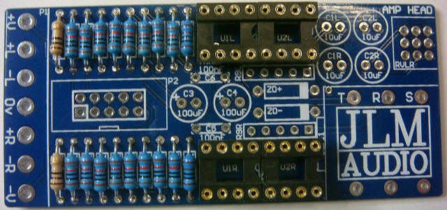
As always fit all parts with value shown on the PCB from the lowest to the highest height parts.
Fit all resistors to the PCB in one go and then solder them in.
Add zeners now if you are using a single rail like our 48v SMPS (eg. 2 x 24v 1w).
To form resistor or zener legs hold resistor body between thumb and finger and run other hand past to bend the legs to 90degrees.
If unsure of resistor color codes push resistor now into multimeter terminals (without test leads fitted) to check resistor value before placing into PCB.
Solder in IC sockets flush to PCB
(Kits comes with 2 x 16pin sockets instead to make fitting easier)
Fit 470R SIP resistor packs.
(Pin with black dot above must go into the square pad as shown)
Fit 2 x blue or yellow 0.1uF mono caps (new kits have 1uF which look identical. Either works fine)
and 4 x 10uF Bi Polar caps either way around.
Fit 2 x 100uF caps with positive long leg into pad marked with +
Straighten legs of pot with long nose pliers and cut off locate tab with side cutters.
The pot can mount in two offset positions on the PCB to allow for different thickness front panels and different jack types.
Pot shown in back position for S2 plastic nut type jacks.
Mount in the front position for S4 chrome nut type jacks as supplied with the kit.
This will push the pot forward so it will bolt up to a 3mm front panel in alignment with the S4 jack with one fibre washer fitted.
For thinner panels fit extra washer to pot and S4 socket. Recommend NOT soldering the pot until you test against the front panel.
The IC socket and jack clash slightly so a small piece needs to be removed with side cutters form the back of the jack.
Finished AMP HEAD ready for 4 x Dual opamps to be fitted.