AMP HEAD Build Thread

Support for JLM Audio Kits

Moderator: Joe Malone

User avatar
Joe Malone
Site Admin
Posts: 2062
Joined: Wed Jan 24, 2007 11:35 pm
Location: Brisbane, Australia
Contact:

AMP HEAD Build Thread

Post by Joe Malone »

AMP HEAD
Small but extremely powerful stereo headphone amp kit with balanced inputs, buss connector, volume control.
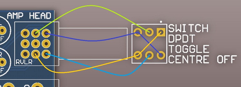
Mono and mute options can be added with one center off toggle switch and no other parts wired across the 4 outside pot terminals. (I will do a drawing of this ASAP)
Several AMP Head's can be power and audio connected with one 10 wire IDC ribbon cable.
Can sum several balanced inputs into AMP HEAD with 10k resistors. (I will do a drawing of this ASAP)
Can handle full overload into short circuit permanently.
Can drive 8 to 600ohm headphones easily.
Frequency response 0, -1dB = 5Hz to 200kHz (or 5Hz to 50kHz if 220pF caps added under PCB across R7 and R8)
THD = 0.006% until onset of clipping.
Idle current = 50mA per AMP HEAD kit.
Max current = 90mA per AMP HEAD kit.
Can be powered by symmetrical +/-12v to +/-24v power rails.
Can also be powered by single 12v to 48v power rail as long as 2 zeners rated at half the voltage used are fitted to the PCB.
(for example 2 x 24v zeners fitted to make +/-24v from one of our 48v SMPS supplies. Any DC connector must be isolated type.)
+/-6v to +/-18v for NE5532AP and most dual type opamps. (Will work with lots of dual opamp type BUT they must be able to drive a 600ohm load.)
+/-12v to +/-24v can be used with OPA2604AP.

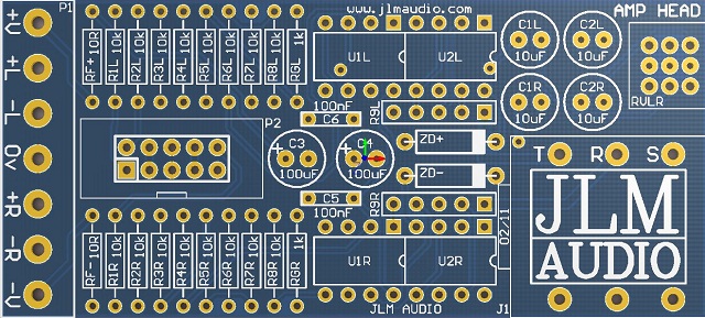
AMP HEAD PCB. Size 3.1" (87.75mm) x 1.4" (35.55mm)
Image

AMP HEAD Parts list

1 x AMP HEAD PCB
1 x Cliff S4 6.3mm Socket
1 x Cliff S4 6.3mm Chrome nut
1 x Cliff S4 6.3mm plastic dress trim
2 x Cliff S4 6.3mm Fiber washer
2 x DIP16 machined pin socket
1 x 10pin IDC header
1 x 3 way terminal block
2 x 2 way terminal block
2 x 100uF 25v electro cap
4 x 10uF 25v Bi Polar electro cap
2 x 100nF mono cap or 1uF mono cap
1 x Dual 10k 9mm log pot
1 x pot washer
1 x pot nut
2 x 470R 5pin SIL Buss resistor packs
2 x 10R carbon 1/4 watt resistor
2 x 1k Metal film 1/4 watt resistor
16 x 10k Metal film 1/4 watt resistor

Options
4 x NE5532AP or OPA2604AP or None

2 x 1watt zener diodes which are only needed in special setups and not included in the kit.
Extra 100nF decoupling caps can be mounted in the ZD+ & ZD- positions if zeners are not used.
If fitting zeners the 2 x 10R RF+ and RF-may need to change value depending on zener diode voltage and +/-V.
Image

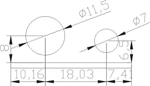
Direct links to cad, corel and pdf files
http://www.jlmaudio.com/AMP%20HEAD/AMP% ... %20OUT.dxf
http://www.jlmaudio.com/AMP%20HEAD/AMP% ... %20OUT.cdr
http://www.jlmaudio.com/AMP%20HEAD/AMP% ... %20OUT.pdf

AMP HEAD BUILD

As always fit all parts with value shown on the PCB from the lowest to the highest height parts.

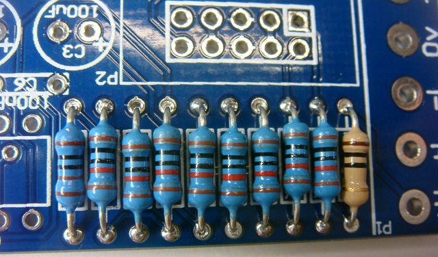
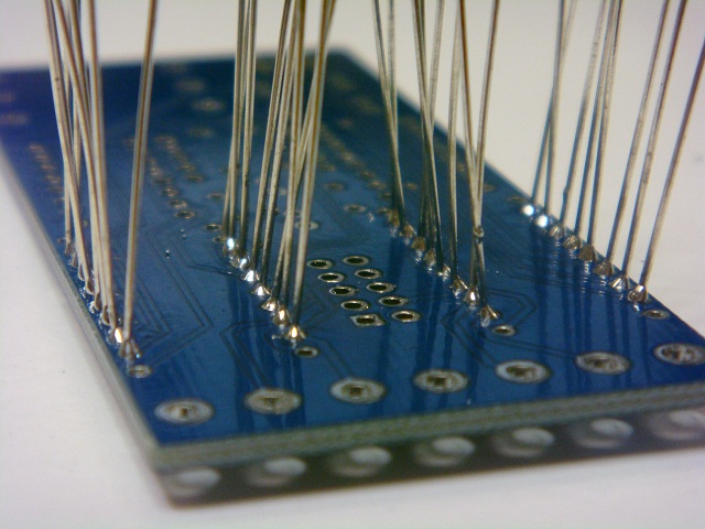
Fit all resistors to the PCB in one go and then solder them in.
Add zeners now if you are using a single rail like our 48v SMPS (eg. 2 x 24v 1w).
To form resistor or zener legs hold resistor body between thumb and finger and run other hand past to bend the legs to 90degrees.
If unsure of resistor color codes push resistor now into multimeter terminals (without test leads fitted) to check resistor value before placing into PCB.
Image
Image

Solder in IC sockets flush to PCB
(Kits comes with 2 x 16pin sockets instead to make fitting easier)
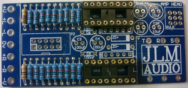
Image

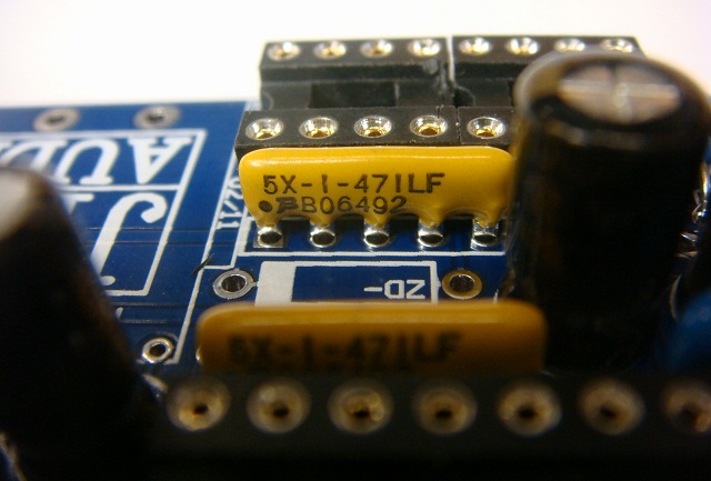
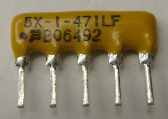
Fit 470R SIP resistor packs.
(Pin with black dot above must go into the square pad as shown)
Image
Image

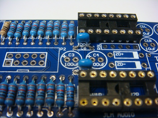
Fit 2 x blue or yellow 0.1uF mono caps (new kits have 1uF which look identical. Either works fine)
and 4 x 10uF Bi Polar caps either way around.
Image

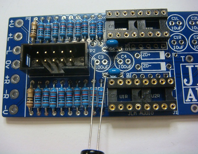
Fit 2 x 100uF caps with positive long leg into pad marked with +
Image

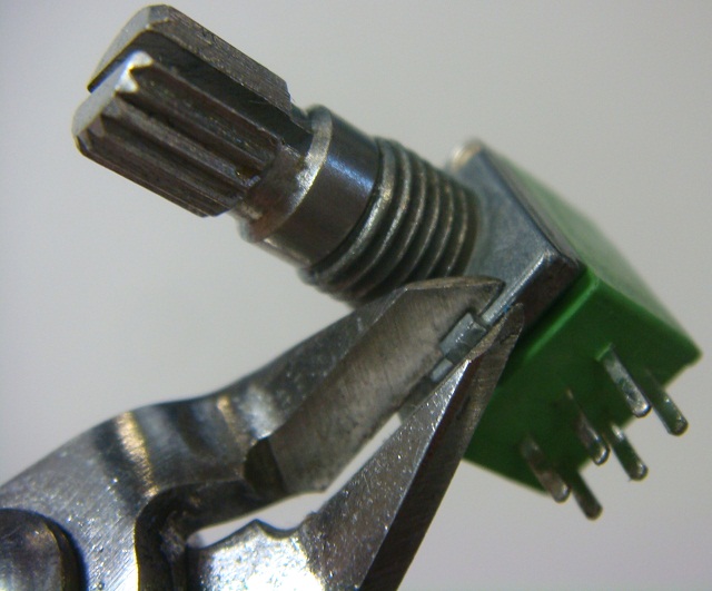
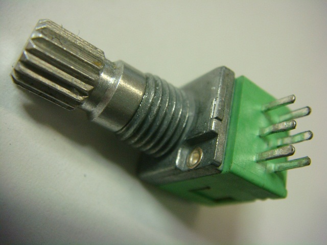
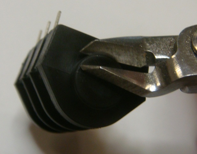
Straighten legs of pot with long nose pliers and cut off locate tab with side cutters.
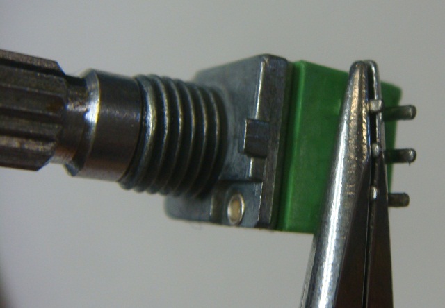
Image
Image
Image

The pot can mount in two offset positions on the PCB to allow for different thickness front panels and different jack types.
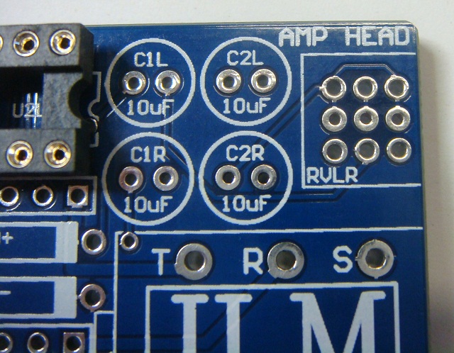
Image

Pot shown in back position for S2 plastic nut type jacks.
Mount in the front position for S4 chrome nut type jacks as supplied with the kit.
This will push the pot forward so it will bolt up to a 3mm front panel in alignment with the S4 jack with one fibre washer fitted.
For thinner panels fit extra washer to pot and S4 socket. Recommend NOT soldering the pot until you test against the front panel.
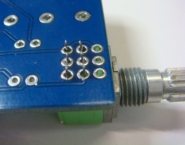
Image

The IC socket and jack clash slightly so a small piece needs to be removed with side cutters form the back of the jack.
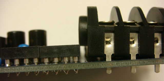
Image
Image

Finished AMP HEAD ready for 4 x Dual opamps to be fitted.
Image
Image
Image
Joe :-)
JLM Audio
Capturing Audio without Injury

cosmodos
Posts: 3
Joined: Tue Mar 29, 2011 5:44 am

Re: AMP HEAD Build Thread

Post by cosmodos »

Joe, I'm THIS close to ordering the Amp Head, but for the lack of build info! When can we expect everything to be up?

Also, how is the amp powered? Just using the 48v SMPS, perhaps?

kante1603
Posts: 86
Joined: Wed Jan 20, 2010 6:12 pm

Re: AMP HEAD Build Thread

Post by kante1603 »

Hello Joe,

I´m highly interested in buying these.
Can you tell us a bit more about the ic-choice,mix,mute and mono options?.
Also which currents we have to calculate with for setting up our psu(s) :?:

Really looking forward to it,

thank you in advance and best regards from germany,

Udo.

User avatar
Joe Malone
Site Admin
Posts: 2062
Joined: Wed Jan 24, 2007 11:35 pm
Location: Brisbane, Australia
Contact:

Re: AMP HEAD Build Thread

Post by Joe Malone »

First post updated with answers to questions.

Keep asking questions here and I will keep updating the first post with the info needed.
Joe :-)
JLM Audio
Capturing Audio without Injury

cosmodos
Posts: 3
Joined: Tue Mar 29, 2011 5:44 am

Re: AMP HEAD Build Thread

Post by cosmodos »

What value of zener do you recommend for use with the 48v SMPS? I see 24v 1W, but recommendations for resistance, leakage, etc., would be helpful.

Thanks alot, Joe!

User avatar
Joe Malone
Site Admin
Posts: 2062
Joined: Wed Jan 24, 2007 11:35 pm
Location: Brisbane, Australia
Contact:

Re: AMP HEAD Build Thread

Post by Joe Malone »

cosmodos wrote:What value of zener do you recommend for use with the 48v SMPS? I see 24v 1W, but recommendations for resistance, leakage, etc., would be helpful.

Thanks alot, Joe!
Any 24v 1watt zener type will work. Needs to be in a standard D0-4 package
Joe :-)
JLM Audio
Capturing Audio without Injury

kante1603
Posts: 86
Joined: Wed Jan 20, 2010 6:12 pm

Re: AMP HEAD Build Thread

Post by kante1603 »

Joe Malone wrote: Mono and mute options can be added with one center off toggle switch and no other parts wired across the 4 outside pot terminals. (I will do a drawing of this ASAP)
Hi Joe,

any news on this or a schemo maybe?
I guess by using a center off toggle switch it must be connected after the de-balancing circiut to link left and right channels,no?
But for mute:I guess the signals are switched to ground in the same place-so it should be a dual-pole switch?
I´m about to order your kits,would be nice to have these options too because they are very very usefull :lol:

Best regards from germany,

Udo.

User avatar
Joe Malone
Site Admin
Posts: 2062
Joined: Wed Jan 24, 2007 11:35 pm
Location: Brisbane, Australia
Contact:

Re: AMP HEAD Build Thread

Post by Joe Malone »

kante1603 wrote:
Joe Malone wrote: Mono and mute options can be added with one center off toggle switch and no other parts wired across the 4 outside pot terminals. (I will do a drawing of this ASAP)
Hi Joe,

any news on this or a schemo maybe?
I guess by using a center off toggle switch it must be connected after the de-balancing circiut to link left and right channels,no?
But for mute:I guess the signals are switched to ground in the same place-so it should be a dual-pole switch?
I´m about to order your kits,would be nice to have these options too because they are very very usefull :lol:

Best regards from germany,

Udo.
HI Udo
Schematic ships with the amp head kit.

MONO/ON/MUTE switching using center off toggle switch.
Image
Joe :-)
JLM Audio
Capturing Audio without Injury

kante1603
Posts: 86
Joined: Wed Jan 20, 2010 6:12 pm

Re: AMP HEAD Build Thread

Post by kante1603 »

Joe Malone wrote:
HI Udo
Schematic ships with the amp head kit.

MONO/ON/MUTE switching using center off toggle switch.
Hi Joe,

thank you very much SIR!!! :D

Best regards,

Udo.

tsvisser
Posts: 5
Joined: Sat May 07, 2011 5:29 am

Re: AMP HEAD Build Thread

Post by tsvisser »

Can sum several balanced inputs into AMP HEAD with 10k resistors. (I will do a drawing of this ASAP)
Is this just a typical passive resistive summing network in front of the audio inputs, or are we talking an ACN somehow?

User avatar
Joe Malone
Site Admin
Posts: 2062
Joined: Wed Jan 24, 2007 11:35 pm
Location: Brisbane, Australia
Contact:

Re: AMP HEAD Build Thread

Post by Joe Malone »

tsvisser wrote:
Can sum several balanced inputs into AMP HEAD with 10k resistors. (I will do a drawing of this ASAP)
Is this just a typical passive resistive summing network in front of the audio inputs, or are we talking an ACN somehow?
Each balanced in is a H pad made from R1 to R4 10k and VR 10k log pot to the +/-in of the opamp.

So to add a 2nd 3rd or 4th etc mix input you can add pairs of 10k to each side of VR if you only want the one master level control for all inputs.
Or make extra H pads and wire to U1 pin 2- and pin 3+ so each balanced input as its own volume control.
Or wire extra H pads to each side of VR if you only want seperate input levels and one master level control for all inputs.
MONO inputs can be done with one H pad with 2 extra 10k resistors on the output.

Hope that makes sense. It would be clear once you get the schematic with the kit.

I will try to add some block diagrams and examples of the above options here when I get time.
Joe :-)
JLM Audio
Capturing Audio without Injury

kante1603
Posts: 86
Joined: Wed Jan 20, 2010 6:12 pm

Re: AMP HEAD Build Thread

Post by kante1603 »

Joe Malone wrote:
Each balanced in is a H pad made from R1 to R4 10k and VR 10k log pot to the +/-in of the opamp.

So to add a 2nd 3rd or 4th etc mix input you can add pairs of 10k to each side of VR if you only want the one master level control for all inputs.
Or make extra H pads and wire to U1 pin 2- and pin 3+ so each balanced input as its own volume control.
Or wire extra H pads to each side of VR if you only want seperate input levels and one master level control for all inputs.
MONO inputs can be done with one H pad with 2 extra 10k resistors on the output.

Hope that makes sense. It would be clear once you get the schematic with the kit.

I will try to add some block diagrams and examples of the above options here when I get time.
Hello Joe,

nice to read this here-so I must not ask and get on your nerves :lol:
Just in case if some H pads are added-could I add on the mute/mono-switch for stereo inputs and a mute-switch for mono additional ins like stated some posts before?
I´m still waiting for parts at the moment,but this is really exciting-I´m thinking on a kind of small satelite-system with some extra-features,having some more than only the "main"-stereo inputs per box,all powered from your ac/dc .....and so forth :mrgreen:

Will be a great experience to me-thanks for all of your awesome work and supporting all of us in such a nice way!

Best regards from germany,

Udo.

User avatar
Joe Malone
Site Admin
Posts: 2062
Joined: Wed Jan 24, 2007 11:35 pm
Location: Brisbane, Australia
Contact:

Re: AMP HEAD Build Thread

Post by Joe Malone »

kante1603 wrote:
nice to read this here-so I must not ask and get on your nerves :lol:
Just in case if some H pads are added-could I add on the mute/mono-switch for stereo inputs and a mute-switch for mono additional ins like stated some posts before?
If adding full stereo H pads in front of the the headamp inputs then yes each stereo input pot can have the mute/on/mono switch added.
I´m still waiting for parts at the moment,but this is really exciting-I´m thinking on a kind of small satelite-system with some extra-features,having some more than only the "main"-stereo inputs per box,all powered from your ac/dc .....and so forth :mrgreen:
If you do a rough drawing on the inputs and control per channel I can show how to best do it with the AMP HEAD.
Will be a great experience to me-thanks for all of your awesome work and supporting all of us in such a nice way!

Best regards from germany,

Udo.
8) :D
Joe :-)
JLM Audio
Capturing Audio without Injury

kante1603
Posts: 86
Joined: Wed Jan 20, 2010 6:12 pm

Re: AMP HEAD Build Thread

Post by kante1603 »

Joe Malone wrote: If you do a rough drawing on the inputs and control per channel I can show how to best do it with the AMP HEAD.
Hi Joe,
attached a quick block diagram on what I´m thinking of,a small satellite-system with a 1RU mainstation containing your ac/dc as psu and the audio-distribution (incoming signals will be xlr on the back and maybe sub-d25s on the front) and an onboard amphead with added H pads.
The satellites should be very small boxes containing 1 amphead each with H pads/mute/mono switches prior to the ampheads input to get a master level control.
Will use it for not-so-experienced singers/narrators (my students at our academy) so that they can control e.g. a playback and their vox or instruments by themselves.
Should be easy to set up although it will be some work concerning mechanics and cabling (you´ve already sent the schematics to me!).

Best,

Udo :wink:
Blockdiagram.jpg
You do not have the required permissions to view the files attached to this post.

kante1603
Posts: 86
Joined: Wed Jan 20, 2010 6:12 pm

Re: AMP HEAD Build Thread

Post by kante1603 »

Hello everybody,

here´s my first take on a phoneamp (for "learning" :mrgreen: ),the Amphead SP (Self-Powered).
Absolutely dead-quiet and powerful.
Used OPA2604s,driven at +/-24v.
Made the optional switch for mono & mute with a 3PDT Centre OFF (3rd pole is for leds).
Case is from Modushop,italy;Panels made by Frank (NRG),germany.

A big THANK YOU to Joe for making this a) possible,b) affordable!!! and c) for always being kind and so helpful!

Here the pics:


Image

Image

Image

Image

Cheers,

Udo :wink:

Post Reply