Regurgitator kit Build Thread
Posted: Fri Feb 25, 2011 6:54 pm
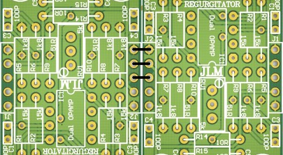
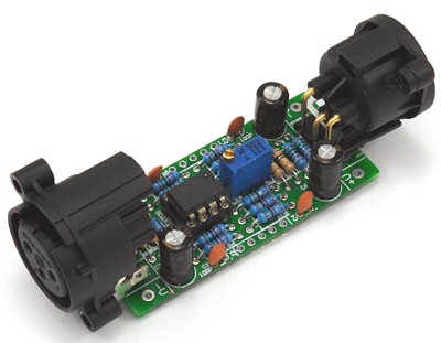
REGURGITATOR
Regurgitator PCB can convert any balanced or unbalanced signal in to balanced or unbalanced signal out with trim pot control from -10db loss to +18db gain.
PCB comes as 8 x V groove snapable PCBs in one with side power connections already joined between the 8 PCB's.
Side power connections still line up when PCB sections are rotated 180 degrees. We can sell the PCBs still joined in 1 to 8 multiples.
Regurgitator 8PAK PCB. Size 8" (203.2mm) x 2.3" (58.42mm)
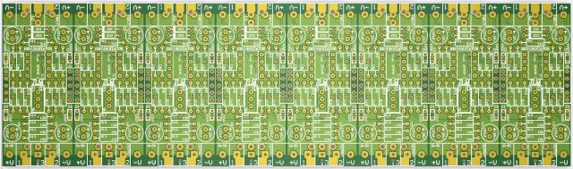
8PAK is V Grooved on top side and only needs 2 or 3 scores with a sharp utility knife
against a straight edge on the underside to cut the joining power rail tracks and
groove the PCB join so they seperate cleanly by bending the PCB section upwards.
XLR spacing is 1" (25.4mm) between joined PCB's
Regurgitator PCB. Size 1" (25.4mm) x 2.3" (58.42mm)
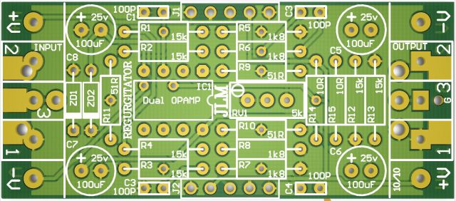
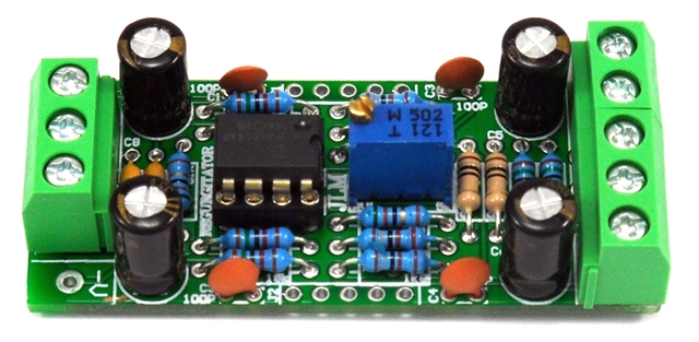
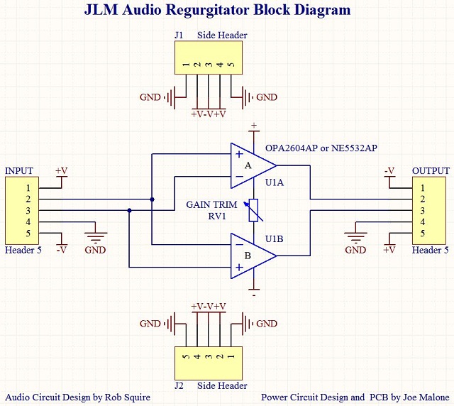
Regurgitator Audio circuit by Rob Squire. Power circuit & PCB by Joe Malone.
Rob's test figures using a 5532 on +/-18V rail
Max balanced output is +29dBu or +26dBm
Noise when trimmed for unity gain is -93dBu unweighted ( this is on the bench with no case and there is a small amount of 50Hz being picked up )
Noise when trimmed for +18dB gain is -73dBu unweighted ( as above )
Noise when trimmed for -10dB gain is -102dBu ( this is the limit of my analyser )
Distortion at unity gain and +10dBu out is 0.002% ( this is the limit of my analyser )
CMRR is -70dBu at unity gain of test unit with normal 1% resistors.
Input Z balanced is 15K and unbalanced is exactly 7.5K looking into either the hot or cold leg.
So this achieves the aim of high CMRR and impedance balanced input. Unlike a normal diff amp where the input Z is different into each leg.
Power rail linking with reversed or seperated PCB's
Regurgitator Parts list
1 x Regurgitator PCB
1 x DIP8 machined pin socket
1 x 3 way terminal block
1 x 2 way terminal block
4 x 100uF 25v electro cap
4 x 100pF Ceramic cap
1 x 5k 25 turn trim pot
2 x 10R carbon 1/4 watt resistor
3 x 51R Metal film 1/4 watt resistor
4 x 1k8 Metal film 1/4 watt resistor
6 x 15k Metal film 1/4 watt resistor
Options
1 x 3 way terminal block or Male XLR or Female XLR
1 x NE5532AP or OPA2604AP or None
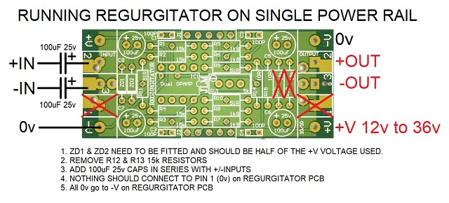
2 x 1watt zener diodes which are only needed in special setups and not included in the kit.
Extra 100nF decoupling caps can be mounted in the ZD1 & ZD2 positions if zeners are not used.
If fitting zeners the 2 x 10R may need to change value depending on zener diode voltage and +/-V.
How to power Regurgitator Kit from a single power rail.
Gain - RGain = R11 + RV1
+18db - 50R
+17dB - 56R
+16dB - 63R
+15dB - 71R
+14dB - 81R
+13dB - 91R
+12dB - 103R
+11dB - 116R
+10dB - 131R
+9dB - 149R
+8dB - 169R
+7dB - 192R
+6dB - 219R
+5dB - 250R
+4dB - 286R
+3dB - 329R
+2dB - 378R
+1dB - 437R
0dB - 507R
-1dB - 593R
-2dB - 696R
-3dB - 822R
-4dB - 983R
-5dB - 1198R
-6dB - 1478R
-7dB - 1870R
-8dB - 2440R
-9dB - 3360R
-10dB - 5080R
-11dB - 9280R
-12dB - 35000R
Regurgitator PCB can convert any balanced or unbalanced signal in to balanced or unbalanced signal out with trim pot control from -10db loss to +18db gain.
PCB comes as 8 x V groove snapable PCBs in one with side power connections already joined between the 8 PCB's.
Side power connections still line up when PCB sections are rotated 180 degrees. We can sell the PCBs still joined in 1 to 8 multiples.
Regurgitator 8PAK PCB. Size 8" (203.2mm) x 2.3" (58.42mm)
8PAK is V Grooved on top side and only needs 2 or 3 scores with a sharp utility knife
against a straight edge on the underside to cut the joining power rail tracks and
groove the PCB join so they seperate cleanly by bending the PCB section upwards.
XLR spacing is 1" (25.4mm) between joined PCB's
Regurgitator PCB. Size 1" (25.4mm) x 2.3" (58.42mm)
Regurgitator Audio circuit by Rob Squire. Power circuit & PCB by Joe Malone.
Rob's test figures using a 5532 on +/-18V rail
Max balanced output is +29dBu or +26dBm
Noise when trimmed for unity gain is -93dBu unweighted ( this is on the bench with no case and there is a small amount of 50Hz being picked up )
Noise when trimmed for +18dB gain is -73dBu unweighted ( as above )
Noise when trimmed for -10dB gain is -102dBu ( this is the limit of my analyser )
Distortion at unity gain and +10dBu out is 0.002% ( this is the limit of my analyser )
CMRR is -70dBu at unity gain of test unit with normal 1% resistors.
Input Z balanced is 15K and unbalanced is exactly 7.5K looking into either the hot or cold leg.
So this achieves the aim of high CMRR and impedance balanced input. Unlike a normal diff amp where the input Z is different into each leg.
Power rail linking with reversed or seperated PCB's
Regurgitator Parts list
1 x Regurgitator PCB
1 x DIP8 machined pin socket
1 x 3 way terminal block
1 x 2 way terminal block
4 x 100uF 25v electro cap
4 x 100pF Ceramic cap
1 x 5k 25 turn trim pot
2 x 10R carbon 1/4 watt resistor
3 x 51R Metal film 1/4 watt resistor
4 x 1k8 Metal film 1/4 watt resistor
6 x 15k Metal film 1/4 watt resistor
Options
1 x 3 way terminal block or Male XLR or Female XLR
1 x NE5532AP or OPA2604AP or None
2 x 1watt zener diodes which are only needed in special setups and not included in the kit.
Extra 100nF decoupling caps can be mounted in the ZD1 & ZD2 positions if zeners are not used.
If fitting zeners the 2 x 10R may need to change value depending on zener diode voltage and +/-V.
How to power Regurgitator Kit from a single power rail.
Gain - RGain = R11 + RV1
+18db - 50R
+17dB - 56R
+16dB - 63R
+15dB - 71R
+14dB - 81R
+13dB - 91R
+12dB - 103R
+11dB - 116R
+10dB - 131R
+9dB - 149R
+8dB - 169R
+7dB - 192R
+6dB - 219R
+5dB - 250R
+4dB - 286R
+3dB - 329R
+2dB - 378R
+1dB - 437R
0dB - 507R
-1dB - 593R
-2dB - 696R
-3dB - 822R
-4dB - 983R
-5dB - 1198R
-6dB - 1478R
-7dB - 1870R
-8dB - 2440R
-9dB - 3360R
-10dB - 5080R
-11dB - 9280R
-12dB - 35000R