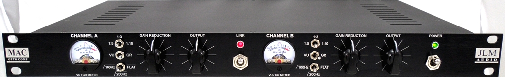
MAC RACK KIT with Green MAC & DINGO PCBs Build Thread
Posted: Sat Apr 03, 2010 10:25 am
MAC Schematic with build info for dingo changes and MAC alignment
http://www.jlmaudio.com/MAC/MACSCH.pdf
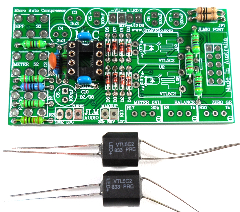
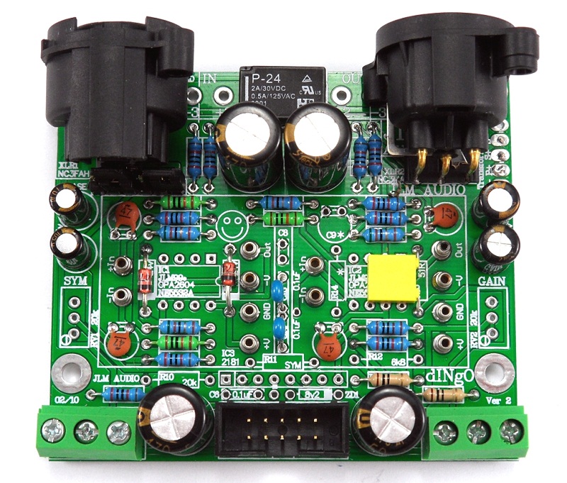
MAC PCB parts kit
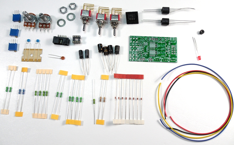
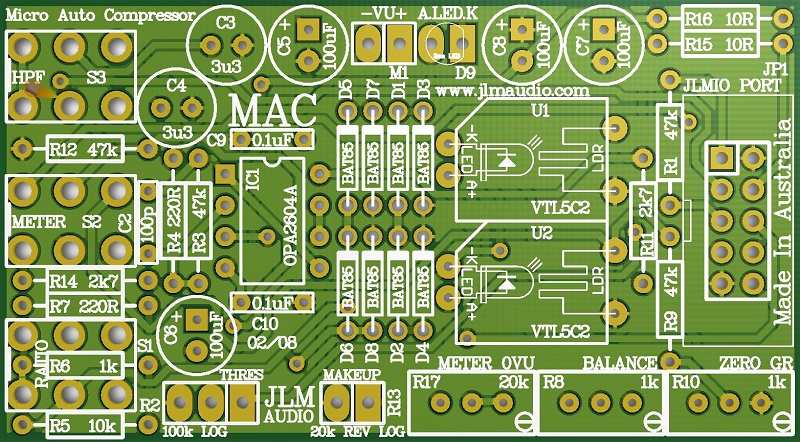
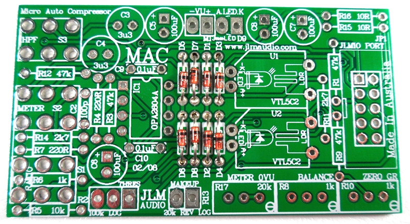
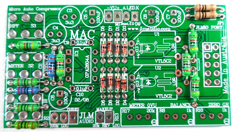
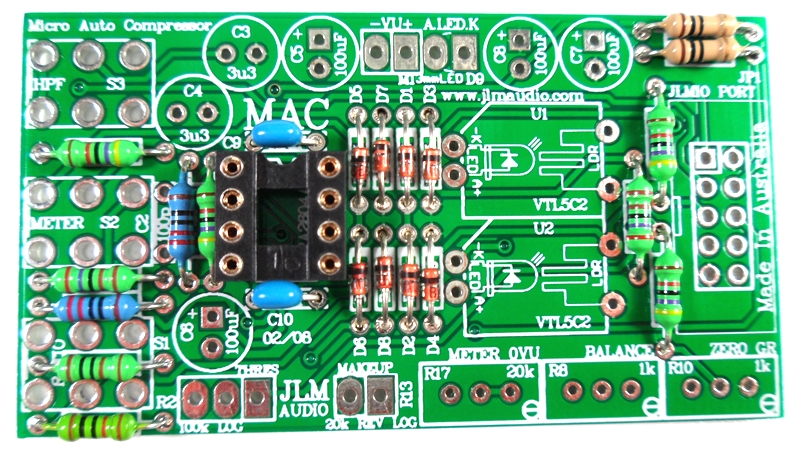
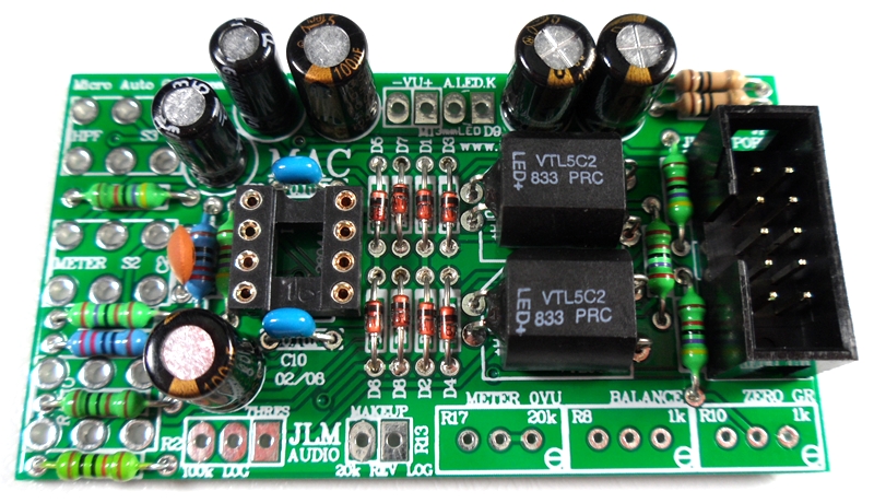
MAC PCB. PCB overlay has all values and there are no options.
so PCB can be assembled directly from overlay.
Notes and Errata (NEW RED COLOURED MAC PCB has all the below errors corrected)
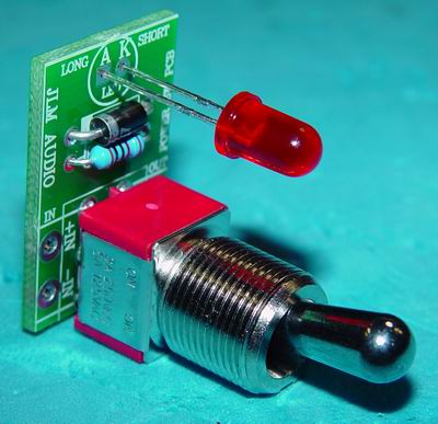
JLM 34mm round VU meter needs D5 to D8 fitted.
LED D9 which is the meter led has A and K marking on MAC PCB are reversed . Rectangle Pad is A (+meter led)
R14 should be changed from 2k7 to 1k8 in all 500 series LA500 versions.
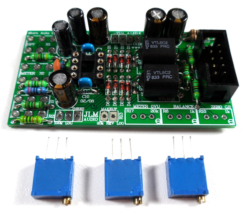
MAC kit now comes with all 1k trim pots replacing the 20k which makes setting the Meter 0VU easier
Fit all 8 x BAT85 diodes with there Cathode POLARIZED black stripe matching the white stripe on the MAC PCB overlay
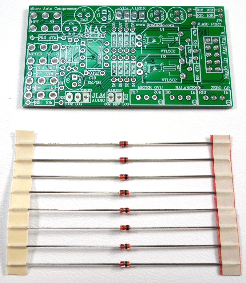
Solder all BAT85 diodes while holding PCB firmly upside down on flat surface. Make sure none of the center close pads are NOT shorted together.
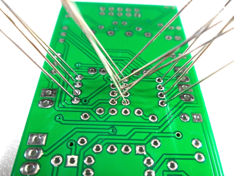
Cut all diodes legs off at top of the solder joint and double check no solder joints missed soldering or are shorted together.
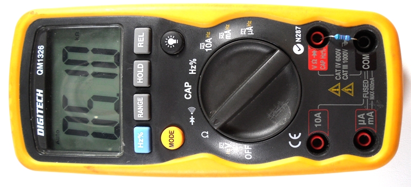
If you are not 100% with resistor colour codes use a multimeter to check values as you place the resistors
Fit all resistors at once bending the legs sightly outwards to hold them in place. This helps to make sure no resistors are put in the wrong position.
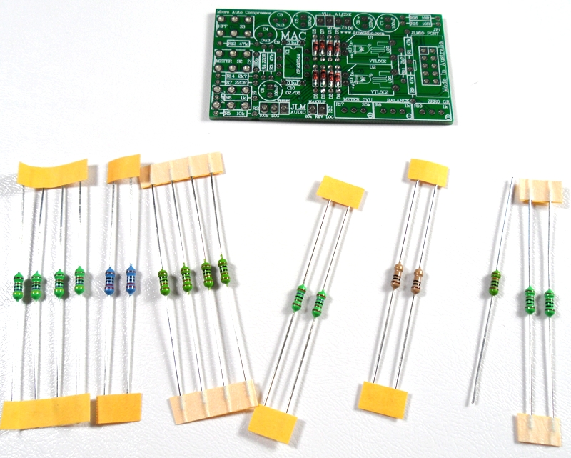
Solder all resistors while holding PCB firmly upside down on flat surface.
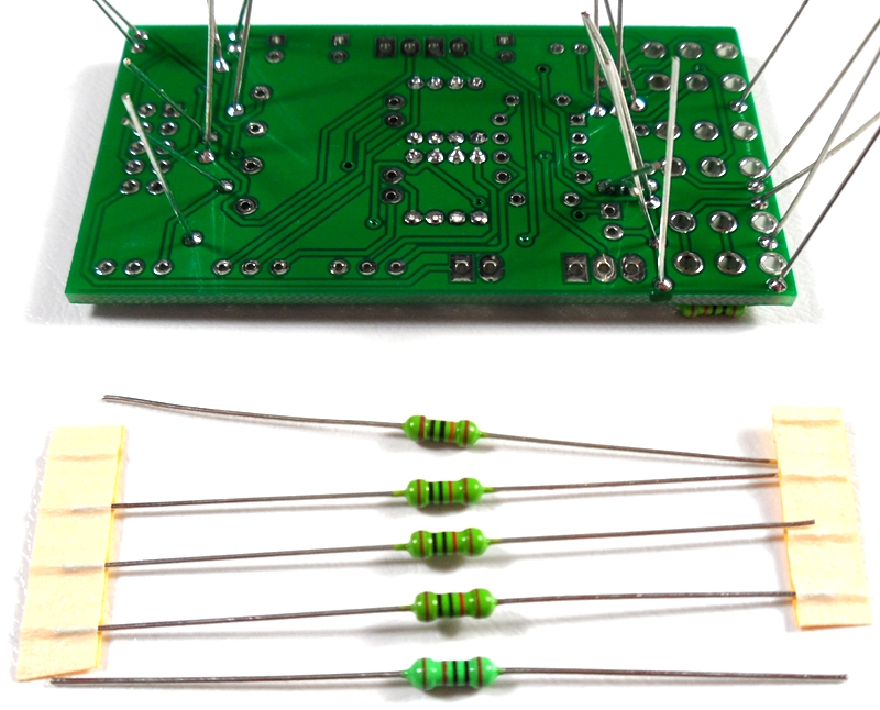
Cut all resistor legs off at top of the solder joint and double check no solder joints missed soldering.
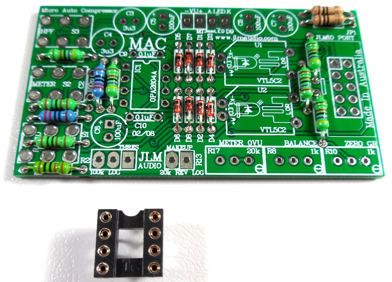
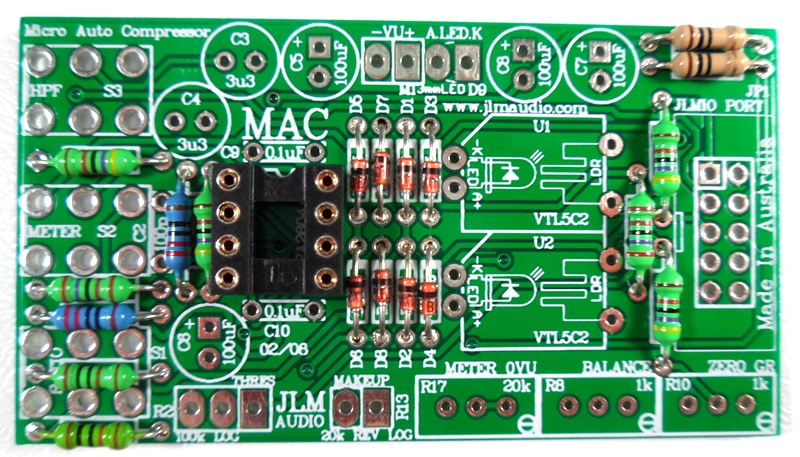
Fit and solder DIP8 socket in other opamp position. Make sure the POLARIZED socket matches the PCB overlay.
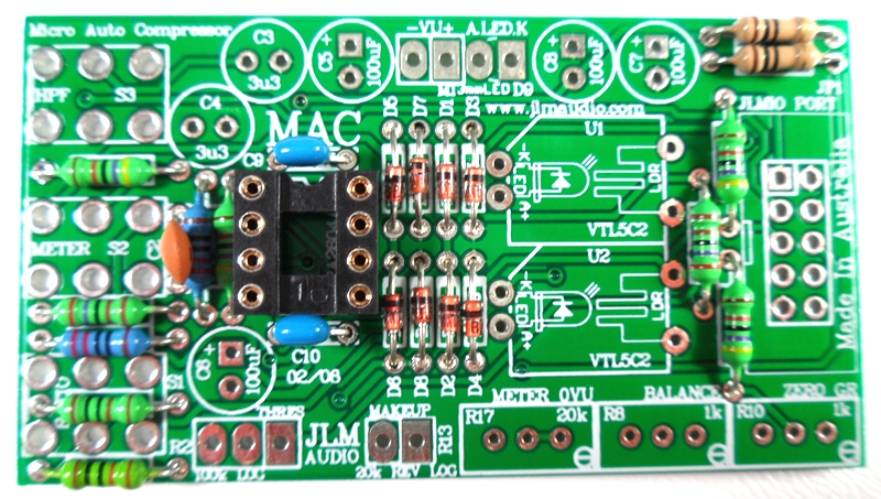
Fit and solder 2 x 0.1uF MONO caps in place.
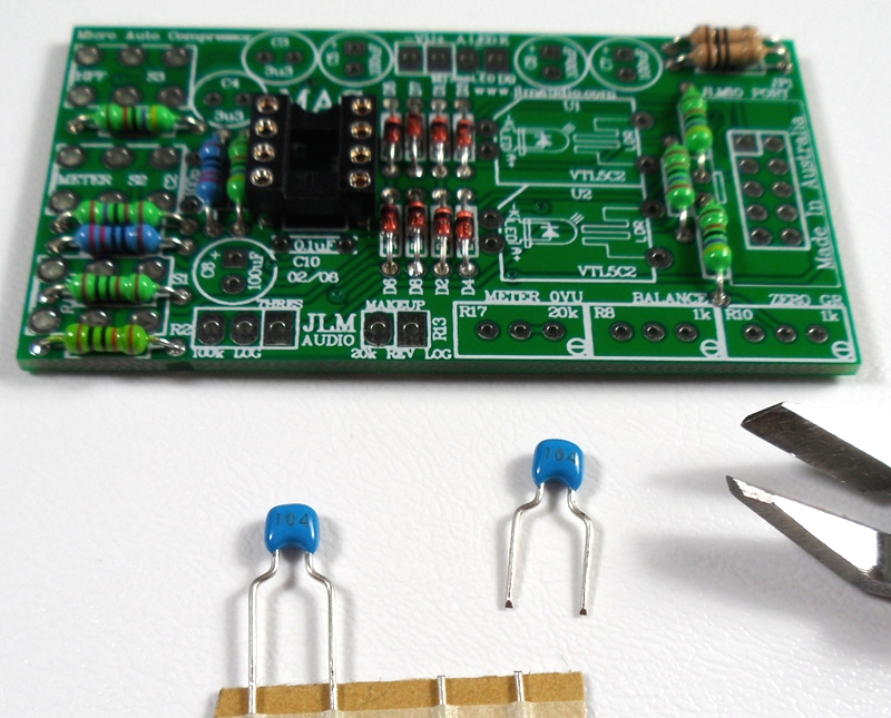
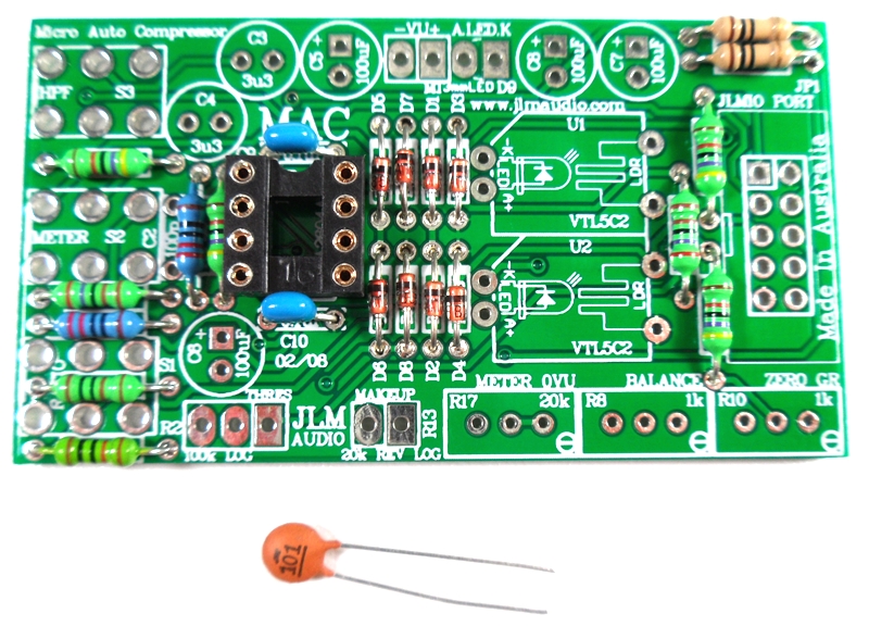
Fit 1 x 100pF ceramic caps in place.
Fit and solder 2 x 5C2 optos in place.

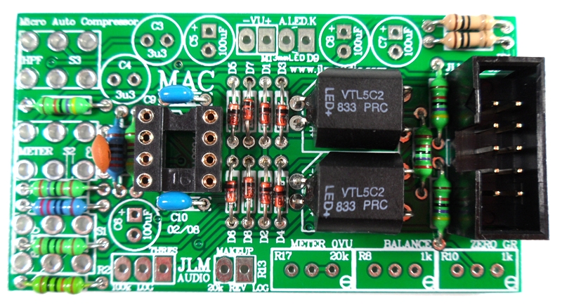
Fit and solder IDC headers in the POLARITY shown. Do not reverse. Triangle on header indicates pin 1 which is the square pad on the PCB.
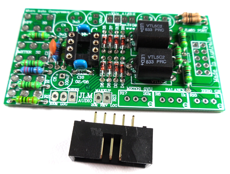
The front opening in the IDC headers should both now be facing as shown below.
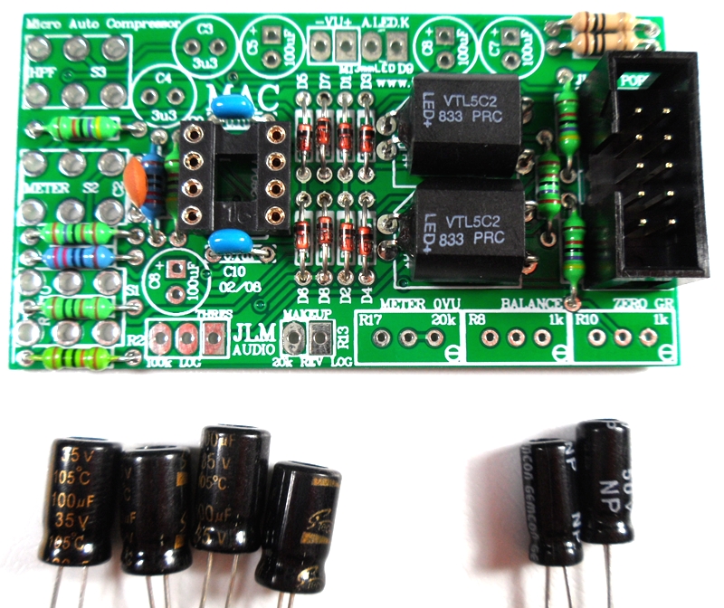
Fit and solder Electro caps to PCB. The 4 x 100uF caps are POLARIZED so must have there long positive leg fitted to + marked on PCB overlay.
2 x 3.3uF acaps are NON polar types so can go in either way around on the PCB.
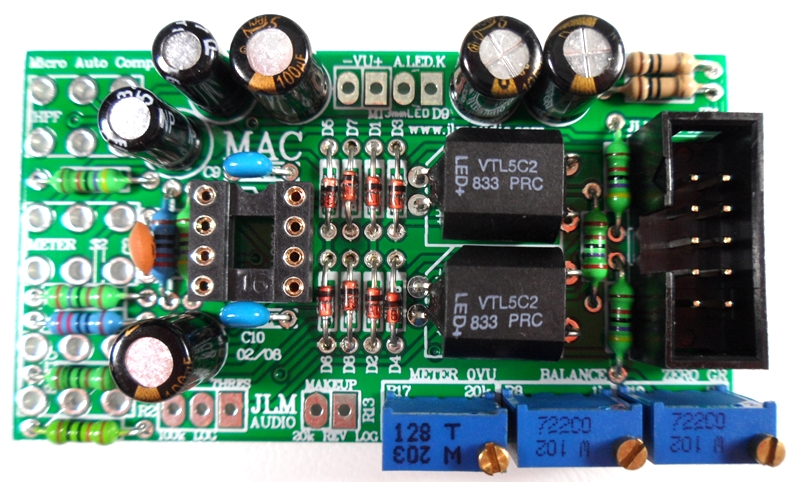
Fit and solder 3 trim pots as shown 20k = 203(replaced with 1k), 1k = 102 code. Place pot so trim screw is in corner shown below
Note MAC kit now comes with all 1k trim pots replacing the 20k which makes setting the Meter 0VU easier
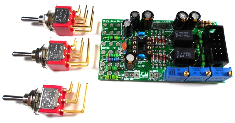
Fit the three switches to the MAC from on top soldering only one front leg and checking they are all aligned before soldering the remaining legs.
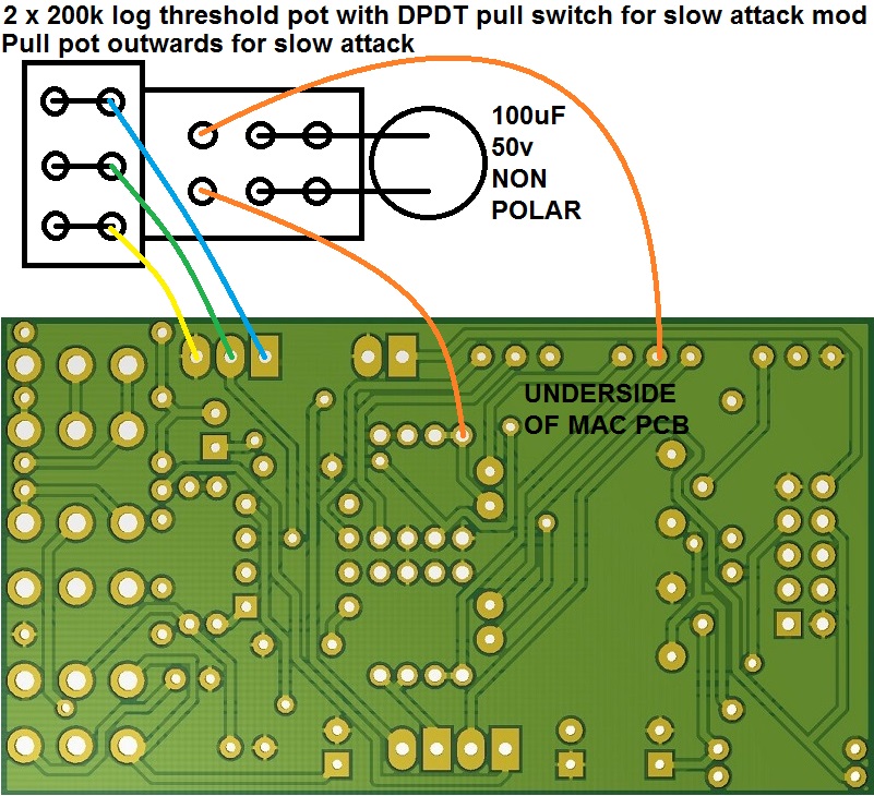
Threshold pot wiring
Fold the pot legs 90 degrees with log nose pliers and solder and link as shown below to make a 100k log pot out of the 2 x 200k log pots.
Slow attack mod wiring attached below as well. Orange wires can go on either way around as cap is non polar.
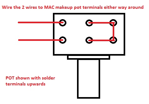
Makeup pot wiring
If Single 10k rev log pot change R16 on dingo PCB to 10k. (If R16 20k already fitted add spare 20k across it under PCB)
or
If 2 x 10k rev log pot wire as 20k rev log makeup pot below
Dingo Schematic
http://www.jlmaudio.com/JLMdINgO.pdf
Dingo PCB built with all changes that are listed on MACSCH.pdf
Note if MAC kit came with single 10k reverse log pot R16 on dingo is changed to 10k. (If 20k already fitted use spare 20k soldered across it under the PCB)
Dingo to JLM111DC wiring
P- to -1
P+ to +1
S+ to +2
S- to -3
Link +3 to -2 on JLM111DC
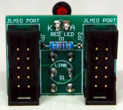
Photo of MAC link PCB
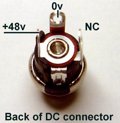
The positive from the DC connector goes to the fuse holder either terminal
Then from the other fuse holder terminal to the +IN on the switch PCB
Then from the +SW to the +V on both Dingo PCB's
The negative from the DC connector goes to the -IN on the switch PCB
Then from the -SW to the -V on both dingo PCB's
Nothing goes to the 0v on either dingo PCB.
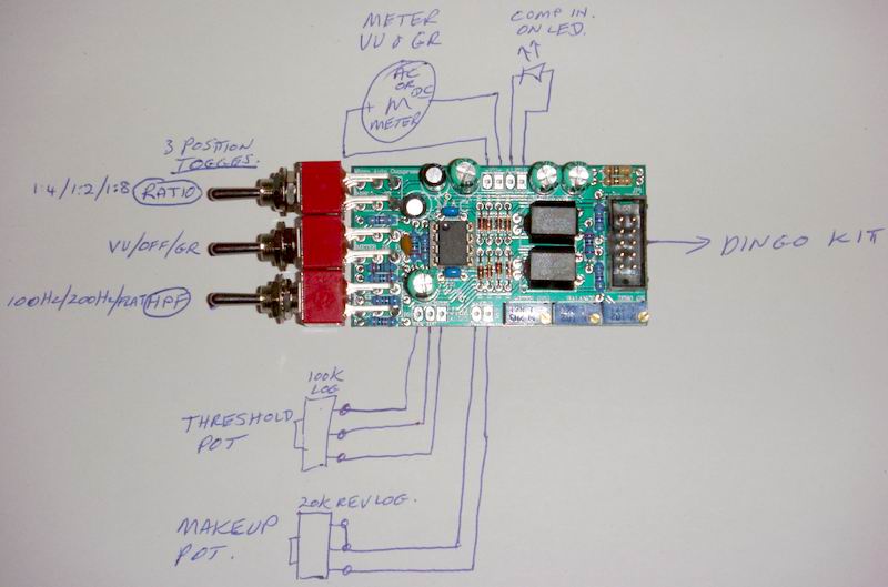
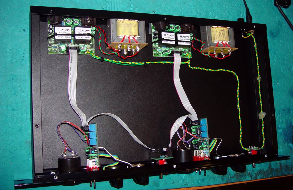
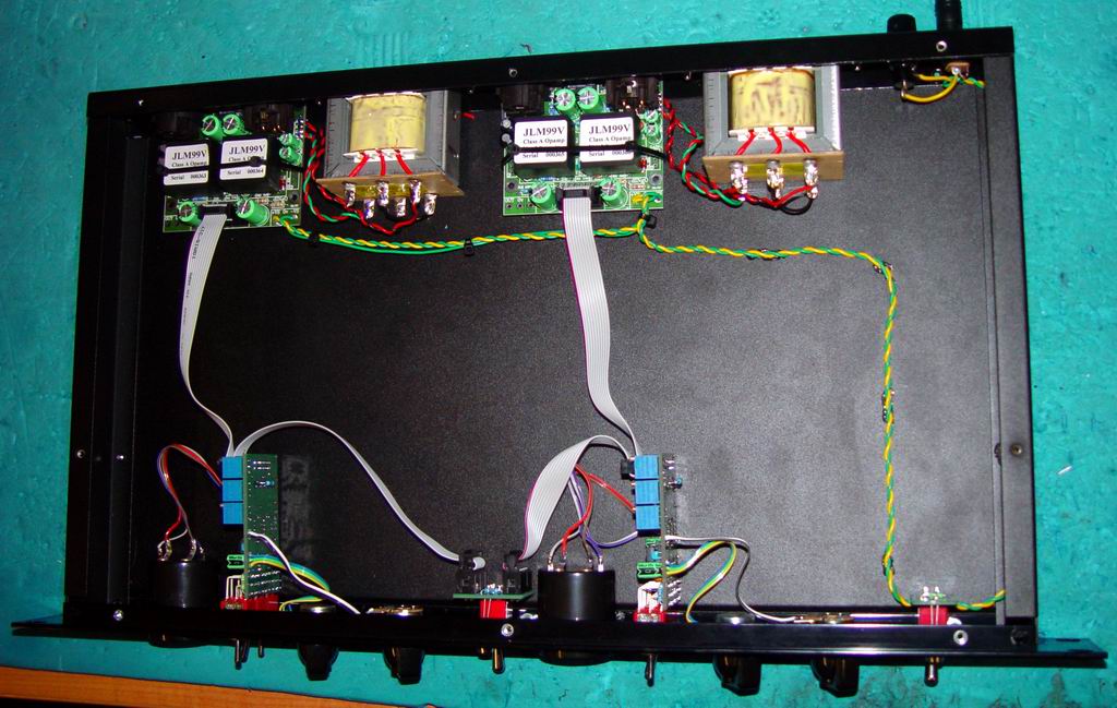
Overview of the general MAC PCB wiring
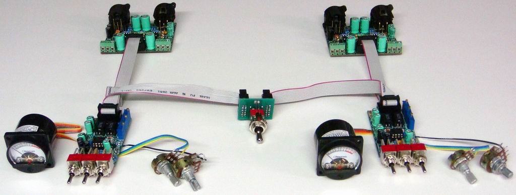
Overview of the general wiring without the case.
Shows most wiring is done by pre made ribbon cables
34mm VU Meters have there LED terminals on the outside with meter terminals on the inside. Meter positive and Anode of the LED on the side marked +
Before plugging in any op amps 99v or OPA2604A on the dingo or MAC pcbs check you have +24v at +V and -24v at -V on the dingo PCB referenced to the 0v terminal.
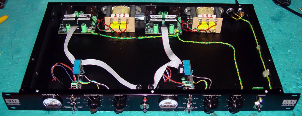
Some internal rack case photo's to help
Before plugging in any op amps 99v or OPA2604A on the dingo or MAC pcbs check you have +24v at +V and -24v at -V on the dingo PCB referenced to the 0v terminal.jlmaudiojlmaudio