Page 9 of 26
Re: Need more bass/bottom from my BA
Posted: Wed Apr 24, 2013 8:10 am
by Joe Malone
rpagala wrote:I compared my BA pre that I built vs my Maudio DMP3 and noticed that the DMP3 has more bottom, is there any way that I can get a little more bottom out of my BA?
By the way I have the JLM input tranny and the 99V, but no output tranny.
I love the tone from the BA but any help to get more bottom out would be appreciated...I dunno maybe a different value cap?
That combo should have huge low end going to a few Hz if built correctly as it is what most guys use as there main drum pres. It sounds like the microphone is losing low end due to the 600ohm input load maybe. Try switching the pad in to see if the low end is bigger or not as this will prove if it is a mic load issue or not. Do you have variable impedance fitted? If so see if the mic pre is fatter sounding at low impedance or high impedance as this will give a clue.
Otherwise send me a photo of the top of the PCB with the opamp removed to check all part values are correct would be a good place to start.
Re: Need more bass/bottom from my BA
Posted: Wed Apr 24, 2013 10:04 am
by rpagala
Joe Malone wrote:rpagala wrote:I compared my BA pre that I built vs my Maudio DMP3 and noticed that the DMP3 has more bottom, is there any way that I can get a little more bottom out of my BA?
By the way I have the JLM input tranny and the 99V, but no output tranny.
I love the tone from the BA but any help to get more bottom out would be appreciated...I dunno maybe a different value cap?
That combo should have huge low end going to a few Hz if built correctly as it is what most guys use as there main drum pres. It sounds like the microphone is losing low end due to the 600ohm input load maybe. Try switching the pad in to see if the low end is bigger or not as this will prove if it is a mic load issue or not. Do you have variable impedance fitted? If so see if the mic pre is fatter sounding at low impedance or high impedance as this will give a clue.
Otherwise send me a photo of the top of the PCB with the opamp removed to check all part values are correct would be a good place to start.
I dont have the impedance pot fitted but I will try again tonight with the pad switched on and compare. I will also take pictures and post it. Thanks Joe...
Re: BA BA2 BA4 BAD Dual99v Build Thread
Posted: Wed Apr 24, 2013 1:15 pm
by rpagala
Joe,
Here are some pictures of the board, do you see anywhere I have done wrong?
Re: BA BA2 BA4 BAD Dual99v Build Thread
Posted: Thu Apr 25, 2013 4:59 pm
by adriengrehier
Hi Joe,
I'm sorry to disturb you, I'm kind a rookie^^ but I enjoy the DIY and your kits are very great by the way.... I'm kind of confuse about how wire the output transformer... My kit is a BA with a JLM111DC Output transformer and I found few explanation but I'm not sure... Can you explain me exactly how I can wire this transformer please?
So far I understand this :
+out(PCB) to +1
0v (PCB) to -1
+2 to -3
-2 to -out (xlr kit)
+3 to + out (xlr kit)
is that correct or not?
last question, why do not you use -out (PCB) wire with -1 (transformer) but 0v?
Thanks a lot for your answer and your DIY projects!
Have a good day
Re: BA BA2 BA4 BAD Dual99v Build Thread
Posted: Thu Apr 25, 2013 7:56 pm
by Joe Malone
adriengrehier wrote:Hi Joe,
I'm sorry to disturb you, I'm kind a rookie^^ but I enjoy the DIY and your kits are very great by the way.... I'm kind of confuse about how wire the output transformer... My kit is a BA with a JLM111DC Output transformer and I found few explanation but I'm not sure... Can you explain me exactly how I can wire this transformer please?
So far I understand this :
+out(PCB) to +1
0v (PCB) to -1
+2 to -3
-2 to -out (xlr kit)
+3 to + out (xlr kit)
is that correct or not?
Correct
last question, why do not you use -out (PCB) wire with -1 (transformer) but 0v?
Because it would require a link between pin 4 and 7 on the DIP8 socket and add an extra 51R in series with the primary of the transformer which will increase the impedance and reduce the drive from the opamp.
Thanks a lot for your answer and your DIY projects!
Have a good day


Re: BA BA2 BA4 BAD Dual99v Build Thread
Posted: Thu Apr 25, 2013 7:59 pm
by Joe Malone
rpagala wrote:Joe,
Here are some pictures of the board, do you see anywhere I have done wrong?
Looks fine.
You can change the BA PCB 51R resistors to 18R with the green and red PCB top JLM111DC transformers to get a better low end extension as well.
Re: BA BA2 BA4 BAD Dual99v Build Thread
Posted: Fri Apr 26, 2013 1:00 pm
by rpagala
Joe,
Do you mean to replace the two 51R to 18R and add an output transformer ?
Re: BA BA2 BA4 BAD Dual99v Build Thread
Posted: Fri Apr 26, 2013 1:22 pm
by Joe Malone
rpagala wrote:Joe,
Do you mean to replace the two 51R to 18R and add an output transformer ?
yes but only if you have a output transformer. With no output transformer the low end is already extended down to a couple of Hz so should be fat as possible already.
Re: FIRST DIY BUILDS: JLM BAs & 1290 Complete!
Posted: Tue May 07, 2013 3:04 pm
by ajsteel
Is there any change in sonic quality using the 220pf capacitors instead of the 47pf capacitors in the opamp section with GAR2520op?
Re: FIRST DIY BUILDS: JLM BAs & 1290 Complete!
Posted: Tue May 07, 2013 3:05 pm
by ajsteel
Also, this may seem dumb but with the ea2622 Input Transformer what colour should pin one be in on the BA PCB?
Re: FIRST DIY BUILDS: JLM BAs & 1290 Complete!
Posted: Tue May 07, 2013 7:09 pm
by Joe Malone
ajsteel wrote:Is there any change in sonic quality using the 220pf capacitors instead of the 47pf capacitors in the opamp section with GAR2520op?
If you mean changing the the 47pF negative feedback bandwidth cap to 220pF on the BA PCB. Both values are way out of the audio band but the 220pF will make the 2520 more stable so is recommended with 2520 type opamps.
Re: FIRST DIY BUILDS: JLM BAs & 1290 Complete!
Posted: Tue May 07, 2013 7:20 pm
by Joe Malone
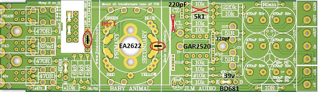
ajsteel wrote:Also, this may seem dumb but with the ea2622 Input Transformer what colour should pin one be in on the BA PCB?
Green. See jpg below for full EA2622 and 2520 on BA PCB setup. If using JLM25HV or JLM25HV FET no BD681 or 39v zener is needed as they can handle the full +/-24v rails.
Re: BA BA2 BA4 BAD Dual99v Build Thread
Posted: Wed May 08, 2013 4:44 pm
by ajsteel
Hi Joe,
Thanks for you info regarding my previous questions. All good now. With the power switch I got a special bag labelled 'use in power switch' that had a LED and a resistor.
I've place the LED on the circuit board, I assumed the long anode goes into the hole that joins the circuit and the short anode goes into the hole that has no electrical connection?
What do I do with the resistor? Do I need it and with the switch are the any jumpers I need to place on it?
Thanks. Learning heaps getting closer to powering up.
A.J.
Re: BA BA2 BA4 BAD Dual99v Build Thread
Posted: Wed May 08, 2013 8:58 pm
by Joe Malone
ajsteel wrote:Hi Joe,
Thanks for you info regarding my previous questions. All good now. With the power switch I got a special bag labelled 'use in power switch' that had a LED and a resistor.
Yes in new BA4 case use the blue led and 220k instead of 10k.
I've place the LED on the circuit board, I assumed the long anode goes into the hole that joins the circuit and the short anode goes into the hole that has no electrical connection?
The Power switch PCB has A and K for the led marked on it. And from memory a square pad for A as well but I will need to check that at the workshop tomorrow.
What do I do with the resistor? Do I need it and with the switch are the any jumpers I need to place on it?
220k replace 10k on power switch PCB when using blue led.
BA4 wiring overlay link below
http://www.jlmaudio.com/Dual99v/BabyAni ... verlay.pdf
Re: BA BA2 BA4 BAD Dual99v Build Thread
Posted: Wed May 08, 2013 10:30 pm
by ajsteel
Hi Joe,
I have LED and the power switch sorted. HOw do I wire the Hi Z pot? Do I use both 2k2 resistors or just 1? And do i solder the resistor across both pins?
Thanks
AJ