BA BA2 BA4 BAD Dual99v Build Thread
Moderator: Joe Malone
-
benranco
- Posts: 5
- Joined: Sat Jun 11, 2011 8:04 am
Re: BA BA2 BA4 BAD Dual99v Build Thread
Thanks again!
-
benranco
- Posts: 5
- Joined: Sat Jun 11, 2011 8:04 am
Re: BA BA2 BA4 BAD Dual99v Build Thread
Hi Joe, I hope you don't mind taking a moment to look at this. I've wired up my friends BAD's and tested them.
One of them works, but the other is not functional and has some strange voltages that I was hoping you might have some insight on. I've tested it with hybrid opamps installed, which work fine in the other BAD. The strange things that I've noticed are:
There seems to be voltage going to the gain pot's lower right terminal (the one that is wired to the board just above the "G1", furthest from the transformer). This voltage reacts to adjustments to the gain knob, and it seems to be inversely correlated with an incorrect voltage on the first opamp's out pin: When the gain pot is set to minimum gain the voltage on the pot is 0 and the voltage on the opamp out is about 43; when the gain pot is set to maximum gain the voltage on the pot is about 16 volts and the voltage on the opamp out is about 39.
Do you have an idea of what might be causing this? I've closely inspected it, and I can't pinpoint any circuit shorts or bad solder joints. Also, I've quadruple-checked the wiring, and I'm sure that it follows the wiring overlay, even though all three wires for the gain pot are black (sorry!).
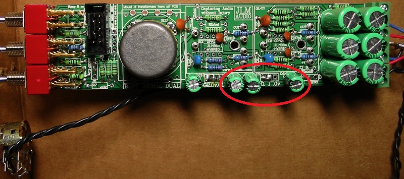
Here are some close-up photos of the preamp if you want to inspect it. The photo might look like I've wired the black transformer wire to the board, but it is floating free.
http://dl.dropbox.com/u/1448493/BAD-bottom.JPG
http://dl.dropbox.com/u/1448493/BAD-top.JPG
Thanks for your help,
Ben
One of them works, but the other is not functional and has some strange voltages that I was hoping you might have some insight on. I've tested it with hybrid opamps installed, which work fine in the other BAD. The strange things that I've noticed are:
There seems to be voltage going to the gain pot's lower right terminal (the one that is wired to the board just above the "G1", furthest from the transformer). This voltage reacts to adjustments to the gain knob, and it seems to be inversely correlated with an incorrect voltage on the first opamp's out pin: When the gain pot is set to minimum gain the voltage on the pot is 0 and the voltage on the opamp out is about 43; when the gain pot is set to maximum gain the voltage on the pot is about 16 volts and the voltage on the opamp out is about 39.
Do you have an idea of what might be causing this? I've closely inspected it, and I can't pinpoint any circuit shorts or bad solder joints. Also, I've quadruple-checked the wiring, and I'm sure that it follows the wiring overlay, even though all three wires for the gain pot are black (sorry!).
Here are some close-up photos of the preamp if you want to inspect it. The photo might look like I've wired the black transformer wire to the board, but it is floating free.
http://dl.dropbox.com/u/1448493/BAD-bottom.JPG
http://dl.dropbox.com/u/1448493/BAD-top.JPG
Thanks for your help,
Ben
Online
-
Joe Malone

- Site Admin
- Posts: 2082
- Joined: Wed Jan 24, 2007 11:35 pm
- Location: Brisbane, Australia
- Contact:
Re: BA BA2 BA4 BAD Dual99v Build Thread
Easy 3 of the 100uF caps are in backwards which will do exactly what you describe. All polarized caps should have there positive facing the front of the PCB (black strip to back of PCB).benranco wrote:Hi Joe, I hope you don't mind taking a moment to look at this. I've wired up my friends BAD's and tested them.
One of them works, but the other is not functional and has some strange voltages that I was hoping you might have some insight on. I've tested it with hybrid opamps installed, which work fine in the other BAD. The strange things that I've noticed are:
There seems to be voltage going to the gain pot's lower right terminal (the one that is wired to the board just above the "G1", furthest from the transformer). This voltage reacts to adjustments to the gain knob, and it seems to be inversely correlated with an incorrect voltage on the first opamp's out pin: When the gain pot is set to minimum gain the voltage on the pot is 0 and the voltage on the opamp out is about 43; when the gain pot is set to maximum gain the voltage on the pot is about 16 volts and the voltage on the opamp out is about 39.
Do you have an idea of what might be causing this? I've closely inspected it, and I can't pinpoint any circuit shorts or bad solder joints. Also, I've quadruple-checked the wiring, and I'm sure that it follows the wiring overlay, even though all three wires for the gain pot are black (sorry!).
Here are some close-up photos of the preamp if you want to inspect it. The photo might look like I've wired the black transformer wire to the board, but it is floating free.
http://dl.dropbox.com/u/1448493/BAD-bottom.JPG
http://dl.dropbox.com/u/1448493/BAD-top.JPG
Thanks for your help,
Ben
Joe 
JLM Audio
Capturing Audio without Injury
JLM Audio
Capturing Audio without Injury
-
benranco
- Posts: 5
- Joined: Sat Jun 11, 2011 8:04 am
Re: BA BA2 BA4 BAD Dual99v Build Thread
Thanks Joe, I completely overlooked that. Problem solved.
-
GraGra
- Posts: 3
- Joined: Tue Aug 09, 2011 3:51 pm
Re: BA BA2 BA4 BAD Dual99v Build Thread
Hi Joe,
I’ve just built my first BA and am having a few issues with it, hoping someone here can help me out.
I am getting signal through to my DIGI 002 line input, however the signal is extremely low.
(BTW this is my first DIY project so apologies in advance if I’ve done something stoopid!)
Here’s the setup:
• JLM14 /99v
• FET DI
• Variable Resistance
• 48v MEPS SMPS
Here’s what I’ve done so far:
• Soft Start Mod – Cut the track, added wire link and fitted #BD681 and #10k
• Variable Z – Left RL off the PCB and fitted 50k pot with 2k2 resistor. Fitted 220pF to CL, 220pF to CZ and wire link across RZ.
• RPad – 120R
• RGain – 68R
• All other components fitted as per the board.
• Connected XLR pcb > FET DI pcb > BA pcb via ribbon cable, with the pink edge lining up with square pad on IDC at each board.
• Connected 0v, Out +, Out – on the BA pcb > 0v, Out +, Out – on the XLR pcb.
• Connected power via the power switch pcb.
I’ve measured all the voltages and most of them are correct-ish (within a volt or two) with the following exceptions:
In + , with phantom power on: 0v
In - , with phantom power on: 0v
Xfmr Red Wire , with phantom power on: 0v
Xfmr Green Wire , with phantom power on: 0v
99v In + , with Opamp not fitted : 22.6v
99v In - , with Opamp not fitted : 0.4v
99v +V , with Opamp not fitted : 45.0v
99v Gnd , with Opamp not fitted : 22.6v
6k8, with phantom on : 41.3v
470uF +, with phantom on : 41.3v (this is the one directly adjacent to the 0v pad)
I should note that originally I had the test voltages all correct, and still had the same low signal issue. Then, when I was tinkering and checking the voltages I got careless and caused a spark across pins 4 & 5 of the IDC on the BA pcb. After that my phantom power LED stopped working and I got the test voltages mentioned above.
I’m hoping I haven’t fried anything too important, but starting to fear the worst…!
Some pics of my dodgy work attached... Any help is greatly appreciated!
Thanks,
Graeme
You do not have the required permissions to view the files attached to this post.
Online
Does the 48v led turn on?
When you turn the power switch on do you hear the relay click on the FET DI? If not check you have the diode on the DI the correct way around.
-
Joe Malone
- Site Admin
- Posts: 2082
- Joined: Wed Jan 24, 2007 11:35 pm
- Location: Brisbane, Australia
- Contact:
Re: BA BA2 BA4 BAD Dual99v Build Thread
OKGraGra wrote:Hi Joe,
I’ve just built my first BA and am having a few issues with it, hoping someone here can help me out.
I am getting signal through to my DIGI 002 line input, however the signal is extremely low.
(BTW this is my first DIY project so apologies in advance if I’ve done something stoopid!)
Here’s the setup:
• JLM14 /99v
• FET DI
• Variable Resistance
• 48v MEPS SMPS
OK CorrectHere’s what I’ve done so far:
• Soft Start Mod – Cut the track, added wire link and fitted #BD681 and #10k
• Variable Z – Left RL off the PCB and fitted 50k pot with 2k2 resistor. Fitted 220pF to CL, 220pF to CZ and wire link across RZ.
• RPad – 120R
• RGain – 68R
• All other components fitted as per the board.
• Connected XLR pcb > FET DI pcb > BA pcb via ribbon cable, with the pink edge lining up with square pad on IDC at each board.
• Connected 0v, Out +, Out – on the BA pcb > 0v, Out +, Out – on the XLR pcb.
• Connected power via the power switch pcb.
Phantom power on is when the 48v toggle is switched away from the PCB.I’ve measured all the voltages and most of them are correct-ish (within a volt or two) with the following exceptions:
In + , with phantom power on: 0v
In - , with phantom power on: 0v
Xfmr Red Wire , with phantom power on: 0v
Xfmr Green Wire , with phantom power on: 0v
Does the 48v led turn on?
When you turn the power switch on do you hear the relay click on the FET DI? If not check you have the diode on the DI the correct way around.
Correct99v In + , with Opamp not fitted : 22.6v
99v In - , with Opamp not fitted : 0.4v
99v +V , with Opamp not fitted : 45.0v
99v Gnd , with Opamp not fitted : 22.6v
This indicates a short on the +in & -in to 0v. Check when switched off for short on both of them? What voltages do you get on both ends of the 3 x 6k8 resistors with nothing plugged into the XLR input? And with no ribbon cable plugged in?6k8, with phantom on : 41.3v
470uF +, with phantom on : 41.3v (this is the one directly adjacent to the 0v pad)
Check 10R is still 10R? If so then the BD681 will be damaged and need replacing. You do not need the BD681 or to do the soft mod as your full rack kit came with a large 40w SMPS. Did you cut the track as well as fit the wire?I should note that originally I had the test voltages all correct, and still had the same low signal issue. Then, when I was tinkering and checking the voltages I got careless and caused a spark across pins 4 & 5 of the IDC on the BA pcb. After that my phantom power LED stopped working and I got the test voltages mentioned above.
When you say low output level. Did you have the opamp fitted? And what voltages did you get on -in and out of the opamp before you shorted the PCB?I’m hoping I haven’t fried anything too important, but starting to fear the worst…!
Some pics of my dodgy work attached... Any help is greatly appreciated!
Joe
JLM Audio
Capturing Audio without Injury
JLM Audio
Capturing Audio without Injury
-
GraGra
- Posts: 3
- Joined: Tue Aug 09, 2011 3:51 pm
Re: BA BA2 BA4 BAD Dual99v Build Thread
The phantom power led is not working.Joe Malone wrote: Phantom power on is when the 48v toggle is switched away from the PCB.
Does the 48v led turn on?
When you turn the power switch on do you hear the relay click on the FET DI? If not check you have the diode on the DI the correct way around.
I can hear the relay on the DI click as soon as I turn power on, and about 5 seconds after I turn it off.
I have the black band on the diode lined up with the diagram on the pcb.
With nothing plugged into the XLR I am now getting all correct measurements again, so I guess that was the cause of the strange measurements previously.This indicates a short on the +in & -in to 0v. Check when switched off for short on both of them? What voltages do you get on both ends of the 3 x 6k8 resistors with nothing plugged into the XLR input? And with no ribbon cable plugged in?
On all three 6k8’s I get 47v with the phantom power ON, and 0v with the phantom power OFF.
I get the same measurements whether the ribbon cable is in or out.
10R is still measuring 10RCheck 10R is still 10R? If so then the BD681 will be damaged and need replacing. You do not need the BD681 or to do the soft mod as your full rack kit came with a large 40w SMPS. Did you cut the track as well as fit the wire?
I understand now - the soft start mod is only for use with the 520mA SMPS, whereas mine is 840mA.
I have already cut the track and fitted the wire. Is this ok or have I will I need a new pcb?
Should I fit a new BD681 perhaps?
Yes opamp was fitted.When you say low output level. Did you have the opamp fitted? And what voltages did you get on -in and out of the opamp before you shorted the PCB?
-In = 23.2v
Out = 23.9
All voltages are now correct again with nothing plugged into XLR but I still have very low output.
-
GraGra
- Posts: 3
- Joined: Tue Aug 09, 2011 3:51 pm
Re: BA BA2 BA4 BAD Dual99v Build Thread
I just realised that I had the impedance pot attached across #10K instead of RLoad. Doh! 
I've fixed that now and retested voltages again.
Most voltages are ok except:
#BD681 : 43.5v
Bottom Right 470uF : 44.3v (looking from above)
Bottom Left 470uF : 21.8v
XFMR Yellow : 21.8v
XFMR Blue : 21.8v
Opamp +In : 21.8v
Opamp -In : 22.4v
Opamp V+ : 43.8v
Opamp Gnd : 21.8v
Still getting the same extremely weak signal - like no gain at all it seems.
If I wind the gain pot up past about 90% the signal is heavily clipped.
My signal chain is an SM57 > BA > DIGI002 line +4db.
I'm actually getting less signal than if just run the SM57 straight into the the DIGI line input.
Im just about out of ideas...
Online
-
Joe Malone
- Site Admin
- Posts: 2082
- Joined: Wed Jan 24, 2007 11:35 pm
- Location: Brisbane, Australia
- Contact:
Re: BA BA2 BA4 BAD Dual99v Build Thread
This correct if the #BD681 is fittedGraGra wrote:I just realised that I had the impedance pot attached across #10K instead of RLoad. Doh!
I've fixed that now and retested voltages again.
Most voltages are ok except:
#BD681 : 43.5v
Bottom Right 470uF : 44.3v (looking from above)
Bottom Left 470uF : 21.8v
XFMR Yellow : 21.8v
XFMR Blue : 21.8v
Opamp +In : 21.8v
Opamp -In : 22.4v
Opamp V+ : 43.8v
Opamp Gnd : 21.8v
Ok this proves the whole circuit is working as the opamp is able to do gain but there is a short on the output. Look for a short on the 51R next to the out opamp pin most likely to 0v. Or on the 470uF 50v cap next to the RGain resistor and back terminal block. Their is only 51R and a 470uF cap between the opamp output and the +out on the BA PCB. So the short only has about 4 possible solder pads. Or the short is on the +out of the XLRIO PCB.Still getting the same extremely weak signal - like no gain at all it seems.
If I wind the gain pot up past about 90% the signal is heavily clipped.
Joe
JLM Audio
Capturing Audio without Injury
JLM Audio
Capturing Audio without Injury
-
ogtravis
- Posts: 3
- Joined: Thu Sep 01, 2011 8:50 am
Re: BA BA2 BA4 BAD Dual99v Build Thread
Hello folks, I'm having some issues with my BA4 (Joe I sent you an email with photos).
I recently built a BA4 for a API style (2622 input xfrm, 2520, and 2503 output xfrm) sound. I finished everything without the output iron and all the voltages were correct. All channels passed signal perfectly, sounded great Joe! . Just the other day I got my ouput xfrmrs and something went dreadfully awry:
I measured the powered coming in from the SMPS and it is now reading 53.6v (??)
SO now the op amp pins for all channels read as follows (no DOA connected):
In+:20.8v
In-:see below
Out: see below
0v:0v
1/2v:21v
v+:42.4
However I am getting odd -In and Out voltages that differ for each channel (no DOA connected):
Channel 1: 3.3v
Channel 2: 8.3v
Channel 3: 1.6v
Channel 4: 4.6v
These are with the 16v zener and #BD681 regulator fitted. I did remove the DIP8 jumper between pin 4 and 7 as of this testing, which had been there when I had been using these channels with no output xfrmrs. I'm not sure if that makes a difference or not.
All this started happening only AFTER I attached the output xfrmrs mind you, and still is happening despite having disconnected everything but +v and 0v. Thanks. Hopefully someone will have some insight, I'm clueless.
I recently built a BA4 for a API style (2622 input xfrm, 2520, and 2503 output xfrm) sound. I finished everything without the output iron and all the voltages were correct. All channels passed signal perfectly, sounded great Joe!
I measured the powered coming in from the SMPS and it is now reading 53.6v (??)
SO now the op amp pins for all channels read as follows (no DOA connected):
In+:20.8v
In-:see below
Out: see below
0v:0v
1/2v:21v
v+:42.4
However I am getting odd -In and Out voltages that differ for each channel (no DOA connected):
Channel 1: 3.3v
Channel 2: 8.3v
Channel 3: 1.6v
Channel 4: 4.6v
These are with the 16v zener and #BD681 regulator fitted. I did remove the DIP8 jumper between pin 4 and 7 as of this testing, which had been there when I had been using these channels with no output xfrmrs. I'm not sure if that makes a difference or not.
All this started happening only AFTER I attached the output xfrmrs mind you, and still is happening despite having disconnected everything but +v and 0v. Thanks. Hopefully someone will have some insight, I'm clueless.
Online
-
Joe Malone
- Site Admin
- Posts: 2082
- Joined: Wed Jan 24, 2007 11:35 pm
- Location: Brisbane, Australia
- Contact:
Re: BA BA2 BA4 BAD Dual99v Build Thread
Check the battery in your multimeter is new as it is rare a SMPS will go high voltage as it has over voltage shutdown protection. Most digital multimeter show higher voltage readings when the battery volts is low.I recently built a BA4 for a API style (2622 input xfrm, 2520, and 2503 output xfrm) sound. I finished everything without the output iron and all the voltages were correct. All channels passed signal perfectly, sounded great Joe!
I measured the powered coming in from the SMPS and it is now reading 53.6v (??)
So what were the voltages before that you thought were correct voltages? Highest v+ should be 32v for real API 2520 with half voltage of 16v if you have the correct 33v zener fitted with #BD681.SO now the op amp pins for all channels read as follows (no DOA connected):
In+:20.8v
In-:see below
Out: see below
0v:0v
1/2v:21v
v+:42.4
These voltages above are correct when no opamps are fitted -in and out will be around 0v and may have small voltages due to the large otuput caps holding some charge.However I am getting odd -In and Out voltages that differ for each channel (no DOA connected):
Channel 1: 3.3v
Channel 2: 8.3v
Channel 3: 1.6v
Channel 4: 4.6v
16v zener is wrong. For API 2520 you need to have a 33v zener which lets the BA make (+/-16v). What zener value do you have on the BA pcb is it really 16v?? You need to get the +v voltage to be +32v before refitting the 2520 opamps unless they our JLM25HV opamps as these do not need the #BD681 reg fitted as they run on +/-24v.These are with the 16v zener and #BD681 regulator fitted.
The pin 4 to pin 7 jumper makes no difference when using a output transformer.I did remove the DIP8 jumper between pin 4 and 7 as of this testing, which had been there when I had been using these channels with no output xfrmrs. I'm not sure if that makes a difference or not.
This could be the case if you were running the API 2520 above there +/-16v rail limit as they can do this ok usually except under low output impedance load like a transformer. Sounds like the API 2520 probably were running on to high a voltage and putting up with it until the low impedance load of the output transformersAll this started happening only AFTER I attached the output xfrmrs mind you, and still is happening despite having disconnected everything but +v and 0v. Thanks. Hopefully someone will have some insight, I'm clueless.
Joe
JLM Audio
Capturing Audio without Injury
JLM Audio
Capturing Audio without Injury
-
ogtravis
- Posts: 3
- Joined: Thu Sep 01, 2011 8:50 am
Re: BA BA2 BA4 BAD Dual99v Build Thread
I put a new battery in the voltmeter, and it is reading the SMPS correctly. Good call, Joe.
Sorry, I meant 33v zener
My op amp pins now read:
V+:37.3
1/2v:18.6
0v:0v
out:4.3
-in:4.3
+in:18.6
This is actually what they have always read, with the exception of the -in and out voltage. I'm not using an original 2520, but a gar2520 from classicAPI which can run on rails up to 20v.
When I'm connecting the primary of the 2503, do I connect it to +out and 0v?
Online
So not sure if you still have a actual problem with the mic pres or not?
-
Joe Malone
- Site Admin
- Posts: 2082
- Joined: Wed Jan 24, 2007 11:35 pm
- Location: Brisbane, Australia
- Contact:
Re: BA BA2 BA4 BAD Dual99v Build Thread
Ok these voltages would be correct if you were using a 39v zener diode (+/-18v). And will be fine for the gar2520 version. If you are really using a 33v zener the +v would not be above 32v.ogtravis wrote:I put a new battery in the voltmeter, and it is reading the SMPS correctly. Good call, Joe.
Sorry, I meant 33v zener
My op amp pins now read:
V+:37.3
1/2v:18.6
0v:0v
out:4.3
-in:4.3
+in:18.6
Yes correct.This is actually what they have always read, with the exception of the -in and out voltage. I'm not using an original 2520, but a gar2520 from classicAPI which can run on rails up to 20v.
When I'm connecting the primary of the 2503, do I connect it to +out and 0v?
So not sure if you still have a actual problem with the mic pres or not?
Joe
JLM Audio
Capturing Audio without Injury
JLM Audio
Capturing Audio without Injury
-
ogtravis
- Posts: 3
- Joined: Thu Sep 01, 2011 8:50 am
Re: BA BA2 BA4 BAD Dual99v Build Thread
OK Joe, sorry for the confusion. I went back through some emails, and you did send me the 39v zeners. I am getting proper voltages.
I managed to get all my channels hooked up to my 2503's today and they all work wonderfully except for channel 3. I'm getting signal to the output, which is porportional to how much I change the gain pot, but the signal is very weak, and when i wind up the gain it is somewhat audible but very distorted. This channel has actually worked before, but I wired up the 2503's and I started getting this problem (which is why I was so confused when my meter was giving me odd readings).
My initial thought was improper 2503 wiring, so I bypassed it, went back to quasi balanced out, still the same problem, only less gain (so the 2503 was wired correctly). My next thought was to rule out the opamp, so I switched the gar1731 with one from a working channel. Same problem exists. All voltages test correctly. Any idea where the problem might be?
Online
Also with the EA2622 you should wire the center two pins on the secondary side to the 0v ground under the pcb so the internal shields are working properly.
EA2622 load parts should be RLoad = Not Fitted, Cload = Not fitted, RZobel = 5.1k, CZobel = 220pF. If you have oscillation problems with your 2520 change the 2 x 47pF caps on the BA PCB to 220pF as well.
Otherwise as usual email me photo of top and bottom of the PCB top and bottom in focus and well lit so I can check it over.
Please keep emails to 4Meg max size as I have had some people sending me 30+Meg emails totally lock up my email lately.
-
Joe Malone
- Site Admin
- Posts: 2082
- Joined: Wed Jan 24, 2007 11:35 pm
- Location: Brisbane, Australia
- Contact:
Re: BA BA2 BA4 BAD Dual99v Build Thread
I think from memory you are using the EA2622 input transformer so have you got the center ratio jumper fitted so the primary of the input transformer is connected correctly?ogtravis wrote:OK Joe, sorry for the confusion. I went back through some emails, and you did send me the 39v zeners. I am getting proper voltages.
I managed to get all my channels hooked up to my 2503's today and they all work wonderfully except for channel 3. I'm getting signal to the output, which is porportional to how much I change the gain pot, but the signal is very weak, and when i wind up the gain it is somewhat audible but very distorted. This channel has actually worked before, but I wired up the 2503's and I started getting this problem (which is why I was so confused when my meter was giving me odd readings).
My initial thought was improper 2503 wiring, so I bypassed it, went back to quasi balanced out, still the same problem, only less gain (so the 2503 was wired correctly). My next thought was to rule out the opamp, so I switched the gar1731 with one from a working channel. Same problem exists. All voltages test correctly. Any idea where the problem might be?
Also with the EA2622 you should wire the center two pins on the secondary side to the 0v ground under the pcb so the internal shields are working properly.
EA2622 load parts should be RLoad = Not Fitted, Cload = Not fitted, RZobel = 5.1k, CZobel = 220pF. If you have oscillation problems with your 2520 change the 2 x 47pF caps on the BA PCB to 220pF as well.
Otherwise as usual email me photo of top and bottom of the PCB top and bottom in focus and well lit so I can check it over.
Please keep emails to 4Meg max size as I have had some people sending me 30+Meg emails totally lock up my email lately.
Joe
JLM Audio
Capturing Audio without Injury
JLM Audio
Capturing Audio without Injury