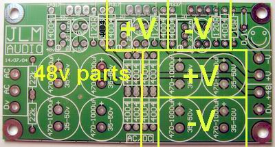
See voltage section breakdown for powerstation and AC/DC kit below. I will try to do some new virtual PCB jpg's when I can to make some easier to read versions.atticmike wrote:hey there,
What am I supposed to do if I for example didn't want the +48V rail from the AC/DC kit?
What parts should I leave out?
Same goes for the powerstation, in case I wouldn't want +V1 and -V1?
Does is suffice if I just leave out the linear regulator 317 / 337?
---
This question is a bit more specific. I'm using two transformers and two psus for a single preamp box (reason being that includes two ssl9k (+ - 16) and two neves ( + - 24). Whereas the transformers and psus are in a separate box. Anyhow, the question is whether I can power all four pres from the same +48V rail and leave the 48 V rail of the other psu out?
As for the shared 48v for 4 mic pres that will work fine as long as both power supplies have there 0v connected together.