AC/DC & POWERSTATION KIT BUILD THREAD
Posted: Sun Jun 14, 2009 10:38 pm
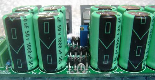
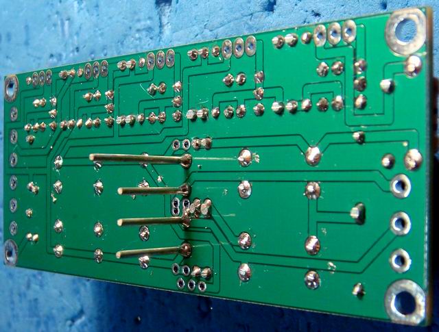
Please note that the AC/DC Ver 2,3 & PowerStation Ver 2,3 PCB's have a extra jumper at the front edge of the PCB to allow the 48v rail to be generated from a Doubler or Tripler
When using a single or dual 22vac to 25vac winding transformer strap D to the centre pad to generate the right volts for the 48v rail. (Shown in photo below)
When using a single or dual 15vac to 18vac winding transformer strap T to the centre pad to generate the right volts for the 48v rail.
All kits now come with 1000uF 50v 105 degree low ESR caps which are 1" (25mm) tall by 0.5" (13mm) diameter.
All kits now have NO 36v 1w Zener as it has been replaced with a 1N4007 for easier setup.
Circuits
Circuit of JLM AC/DC (Ver. 4) 3 rail Power supply PCB (JLM AC/DC Ver. 4 PCB)
Circuit of JLM Power Station (Ver. 3) 5 rail Power supply PCB (JLM POWER STATION Ver. 3 PCB)
Parts list
BOM of JLM AC/DC (Ver. 4) 3 rail Power supply PCB (AC/DC Ver 4 Power Supply Kit.txt)
BOM of JLM Power Station (Ver. 3) 5 rail Power supply PCB (Powerstation Ver 3 Power Supply Kit.txt)
ALL 120/240v mains wiring MUST be done by a Qualified Technician.
What Power Transformer secondary volts do I need?
The transformer secondary AC volts needed depends on the +/- dc regulated voltage rails wanted. If you want +/-34vdc regulated for 99v you will need 37v to 40v unregulated which would need one or two 26vac to 28vac transformer secondary windings. This might sound like a odd voltage value but in reality when you take the fully loaded voltage and add the regulation percentage specified by the transformer manufacture to get the no load voltage it all works out. So if the voltage output of a transformer is stated as 25vac at full load by adding the 10 to 20% regulation amount you will end up with 27.5vac to 30vac unloaded with is perfect. Also if you use one 25vac winding then the refresh rate to the large storage capacitors will be 50 or 60Hz depending on the country you are in. If you use two 25vac windings or a 50vac centre tapped winding the refresh rate will be 100Hz or 120Hz which will almost half the amount of ripple on the large storage caps. Also the dual 25vac has symmetrical ripple.
NEW JLM Audio Power transformer VA wattage and Heatsink C/W rating calculator
http://www.jlmaudio.com/ACDC%20Calculator.htm
(Hold down shift and click on link to open in new window)
PowerStation PCB and kit of parts
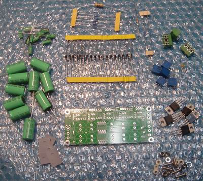
All PowerStation Ver 2 & AC/DC Ver 2 PCB's have been bare board tested for shorts and breaks in tracks but it is always worth having a good look over the PCB for any damage before starting to assemble.
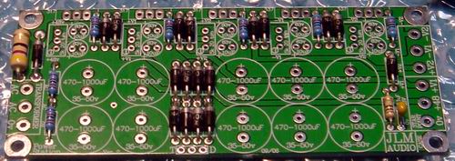
1.Install all resistors in there correct locations using chart to the left or better still by using a multimeter with no leads fitted and bending the legs of the resistor and putting them in the meter sockets to double check you have the right value before putting it into the PCB. Fit all resistors before soldering them as this can also help check that you haven't put a resistor in the wrong place.
2.Install all diodes which all face in one direction. (Grey band lines up white white band on PCB)
Note. Leave out D1 to D4 if using the 4 to 6A bridge rectifier
3.Install 0.1uF bead cap which can go in either way around.
4. Install the 5 x 5k trims pots with adjust screws closest to the large caps as shown.
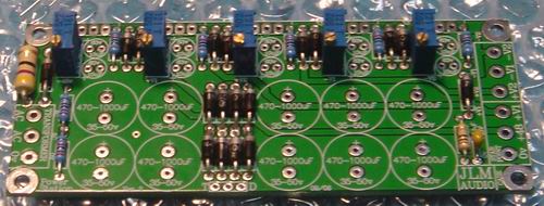
5. Install 10 x 10uF 63v caps all with there positive long leg to the left as shown.
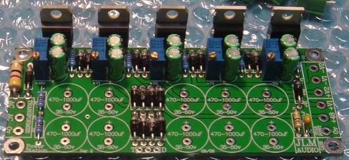
6. Install the 3 x LM317 positive regulators in the 3 left positions and the 2 x LM337 negative regulators in the 2 right positions. Now is a good time to use the mounted regs to mark up the 5 mounting holes in the heatsink or metal case side panel. You can also put the regulators legs in from under the PCB if you want to bolt the regulators to the same surface as the PCB mounting holes
(AC/DC has 2 x LM317 to the left and 1 x LM337 to the right)
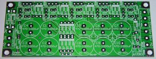
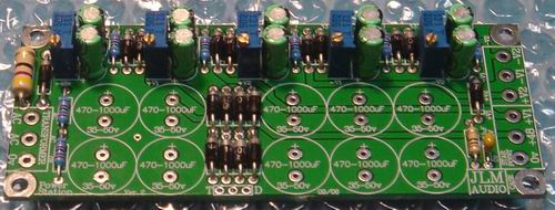
7. Install 10 x 1000uF 50v caps all with there positive long leg to the top as shown.
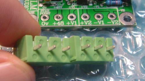
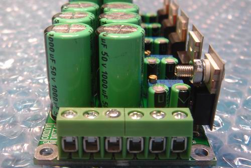
8. Slide terminal blocks that sit beside each other into each others tongue and groove joint and then write with a permanent black pen what each terminal is on the terminal block before installing them to the PCB. (eg 0v +48 +24 +18v -24v -18v)
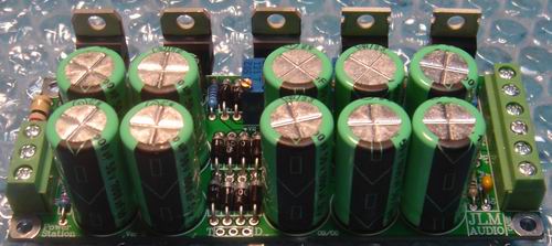
9. The PowerStation PCB with terminal blocks fitted.
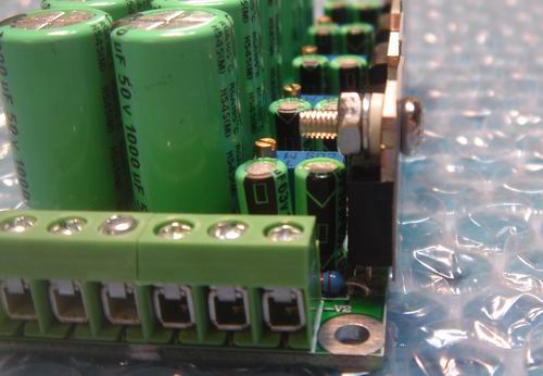
10. You now need to jumper either T (Tripler) to the centre pad if you are using a 15vac to 18vac transformer or D (Doubler) to the centre pad if you are using a 22vac to 28vac transformer to get the pump charge for the 48v rail to work.
11. Check the underside of the PCB for any shorts between any solder pads. Also recheck all parts are in the right way around. You can now connect the 15vac to 28vac transformer to the left side AC connections. Sit the power supply on a rubber mat and connect a volt meter to 0v and +48v DC outputs. Stand back and turn on. If there is no smoke and the meter reads about 27vdc to 33volts dc all is looking good. If you get higher than 48v on power up there is a short somewhere on the PCB. Use a small screw driver to adjust the 48v 25 turn trim pot until you have 48v. Turn off and move the volt meter to +V1 and turn on. Adjust for the voltage you need and repeat for all dc outputs.
(If any output voltage does not follow the trim pot up or down smoothly or seem stuck on full voltage do not just keep turning the trim pot as there is a fault and if you keep winding the pot down it will burn the 5k trim pot and 120R resistor)(Trim pots come set to half way when new and no not need any adjustment before first power up)
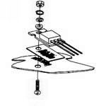
12. Once all voltages are set you are ready to bolt the power supply to the metal case or heatsink. Peal the white paper backing of the stick on insulators and stick then on to each regulators metal tab. Make sure there are no sharp edges around the holes drilled into the case or heatsink that will cut the silicon insulators. The grey silicon washers do not require thermal paste at all.
(We use the 3 or 5 reg bolts to hold the PCB in place to the back or side panel in our full mic pre kits but add 2 x 10mm hex threaded standoffs to the front edge of the PCB to stop the PCB from tilting. We do not bolt the standoffs to the bottom panel as this allows the top and bottom panel to be removed easily for servicing. A small piece of stick on foam on the top of the 1000uF caps pins the power supply between the top and bottom panel securely)
13. The 3 x 10mm bolt will go through the metal case or heatsink then through the insulator and regulator tab. Slide the white bush down the bolt so the thin tube part slide inside the regulator mounting hole. Fit lock washer and nut and do up firmly but do not over tighten. Check with a ohmmeter that the regulator metal tabs and heatsink or metal case are not shorted together.
14. Turn on and test that the DC outputs are still adjusted ok before connecting up DC outputs and Case ground to right hand front bolt hole on the PowerStation or the Bolt hole above the smiley face on the AC/DC.
(If the 10ohm resistor burns up when power is turned on there is a short on one of the regulator tabs to the heatsink or metal case)
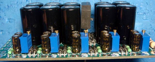
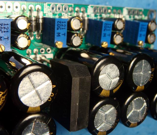
Photos of 4Amp or 6Amp bridge fitted to Powerstation Ver 3 PCB. Leave out D1 to D4 if using 4A bridge.
(Fit the Bridge so it stands with its top at the same height as the 1000uF caps as shown below)
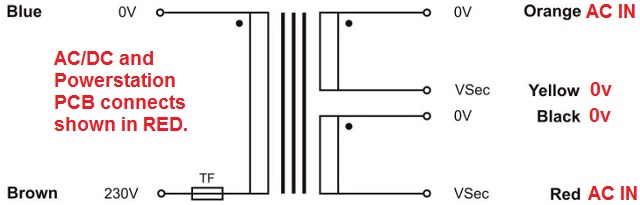
Sometimes the in phase wire of the secondary windings are shown with 0v which can be confused with the PCB 0v but it must be wired to the AC/DC or Powerstation kit as shown below.
When using a single or dual 22vac to 25vac winding transformer strap D to the centre pad to generate the right volts for the 48v rail. (Shown in photo below)
When using a single or dual 15vac to 18vac winding transformer strap T to the centre pad to generate the right volts for the 48v rail.
All kits now come with 1000uF 50v 105 degree low ESR caps which are 1" (25mm) tall by 0.5" (13mm) diameter.
All kits now have NO 36v 1w Zener as it has been replaced with a 1N4007 for easier setup.
Circuits
Circuit of JLM AC/DC (Ver. 4) 3 rail Power supply PCB (JLM AC/DC Ver. 4 PCB)
Circuit of JLM Power Station (Ver. 3) 5 rail Power supply PCB (JLM POWER STATION Ver. 3 PCB)
Parts list
BOM of JLM AC/DC (Ver. 4) 3 rail Power supply PCB (AC/DC Ver 4 Power Supply Kit.txt)
BOM of JLM Power Station (Ver. 3) 5 rail Power supply PCB (Powerstation Ver 3 Power Supply Kit.txt)
ALL 120/240v mains wiring MUST be done by a Qualified Technician.
What Power Transformer secondary volts do I need?
The transformer secondary AC volts needed depends on the +/- dc regulated voltage rails wanted. If you want +/-34vdc regulated for 99v you will need 37v to 40v unregulated which would need one or two 26vac to 28vac transformer secondary windings. This might sound like a odd voltage value but in reality when you take the fully loaded voltage and add the regulation percentage specified by the transformer manufacture to get the no load voltage it all works out. So if the voltage output of a transformer is stated as 25vac at full load by adding the 10 to 20% regulation amount you will end up with 27.5vac to 30vac unloaded with is perfect. Also if you use one 25vac winding then the refresh rate to the large storage capacitors will be 50 or 60Hz depending on the country you are in. If you use two 25vac windings or a 50vac centre tapped winding the refresh rate will be 100Hz or 120Hz which will almost half the amount of ripple on the large storage caps. Also the dual 25vac has symmetrical ripple.
NEW JLM Audio Power transformer VA wattage and Heatsink C/W rating calculator
http://www.jlmaudio.com/ACDC%20Calculator.htm
(Hold down shift and click on link to open in new window)
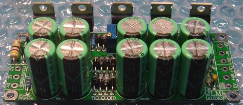
PowerStation PCB and kit of parts
All PowerStation Ver 2 & AC/DC Ver 2 PCB's have been bare board tested for shorts and breaks in tracks but it is always worth having a good look over the PCB for any damage before starting to assemble.
1.Install all resistors in there correct locations using chart to the left or better still by using a multimeter with no leads fitted and bending the legs of the resistor and putting them in the meter sockets to double check you have the right value before putting it into the PCB. Fit all resistors before soldering them as this can also help check that you haven't put a resistor in the wrong place.
2.Install all diodes which all face in one direction. (Grey band lines up white white band on PCB)
Note. Leave out D1 to D4 if using the 4 to 6A bridge rectifier
3.Install 0.1uF bead cap which can go in either way around.
4. Install the 5 x 5k trims pots with adjust screws closest to the large caps as shown.
5. Install 10 x 10uF 63v caps all with there positive long leg to the left as shown.
6. Install the 3 x LM317 positive regulators in the 3 left positions and the 2 x LM337 negative regulators in the 2 right positions. Now is a good time to use the mounted regs to mark up the 5 mounting holes in the heatsink or metal case side panel. You can also put the regulators legs in from under the PCB if you want to bolt the regulators to the same surface as the PCB mounting holes
(AC/DC has 2 x LM317 to the left and 1 x LM337 to the right)
7. Install 10 x 1000uF 50v caps all with there positive long leg to the top as shown.
8. Slide terminal blocks that sit beside each other into each others tongue and groove joint and then write with a permanent black pen what each terminal is on the terminal block before installing them to the PCB. (eg 0v +48 +24 +18v -24v -18v)
9. The PowerStation PCB with terminal blocks fitted.
10. You now need to jumper either T (Tripler) to the centre pad if you are using a 15vac to 18vac transformer or D (Doubler) to the centre pad if you are using a 22vac to 28vac transformer to get the pump charge for the 48v rail to work.
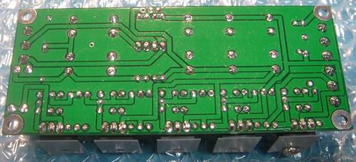
11. Check the underside of the PCB for any shorts between any solder pads. Also recheck all parts are in the right way around. You can now connect the 15vac to 28vac transformer to the left side AC connections. Sit the power supply on a rubber mat and connect a volt meter to 0v and +48v DC outputs. Stand back and turn on. If there is no smoke and the meter reads about 27vdc to 33volts dc all is looking good. If you get higher than 48v on power up there is a short somewhere on the PCB. Use a small screw driver to adjust the 48v 25 turn trim pot until you have 48v. Turn off and move the volt meter to +V1 and turn on. Adjust for the voltage you need and repeat for all dc outputs.
(If any output voltage does not follow the trim pot up or down smoothly or seem stuck on full voltage do not just keep turning the trim pot as there is a fault and if you keep winding the pot down it will burn the 5k trim pot and 120R resistor)(Trim pots come set to half way when new and no not need any adjustment before first power up)
12. Once all voltages are set you are ready to bolt the power supply to the metal case or heatsink. Peal the white paper backing of the stick on insulators and stick then on to each regulators metal tab. Make sure there are no sharp edges around the holes drilled into the case or heatsink that will cut the silicon insulators. The grey silicon washers do not require thermal paste at all.
(We use the 3 or 5 reg bolts to hold the PCB in place to the back or side panel in our full mic pre kits but add 2 x 10mm hex threaded standoffs to the front edge of the PCB to stop the PCB from tilting. We do not bolt the standoffs to the bottom panel as this allows the top and bottom panel to be removed easily for servicing. A small piece of stick on foam on the top of the 1000uF caps pins the power supply between the top and bottom panel securely)
13. The 3 x 10mm bolt will go through the metal case or heatsink then through the insulator and regulator tab. Slide the white bush down the bolt so the thin tube part slide inside the regulator mounting hole. Fit lock washer and nut and do up firmly but do not over tighten. Check with a ohmmeter that the regulator metal tabs and heatsink or metal case are not shorted together.
14. Turn on and test that the DC outputs are still adjusted ok before connecting up DC outputs and Case ground to right hand front bolt hole on the PowerStation or the Bolt hole above the smiley face on the AC/DC.
(If the 10ohm resistor burns up when power is turned on there is a short on one of the regulator tabs to the heatsink or metal case)
Photos of 4Amp or 6Amp bridge fitted to Powerstation Ver 3 PCB. Leave out D1 to D4 if using 4A bridge.
(Fit the Bridge so it stands with its top at the same height as the 1000uF caps as shown below)
Sometimes the in phase wire of the secondary windings are shown with 0v which can be confused with the PCB 0v but it must be wired to the AC/DC or Powerstation kit as shown below.