VU BUFFER KIT BUILD THREAD
Posted: Sun Jun 14, 2009 8:37 pm
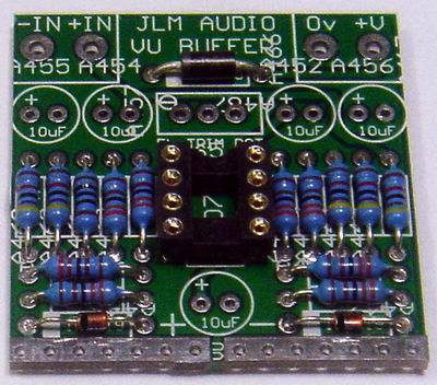
VU buffer kit parts
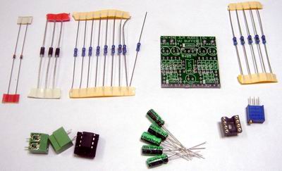
47k = Yellow Violet Black red
3k3 = Orange Orange Black Brown
100R = Brown Black Black Black
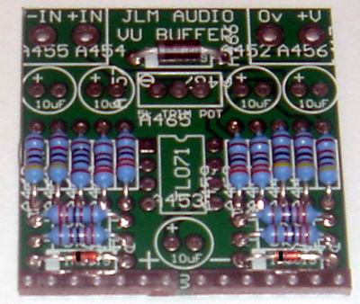
Install resistors and diodes with there white or black stripes to the left
Top Diode can be any type 1N4001,2,4,7 or BAT85 or 1N5819 as it is only to stop reverse power wiring from damaging the opamp.
Bottom 2 diodes need to be Schottky BAT85 1N5819 etc or Germanium OA47, OA91 etc type for the meter to track correctly at low levels.
Note 1. When using a meter with internal rectifiers like our Nissei AL29 do the mod shown below to disable the VU buffer recitifier.

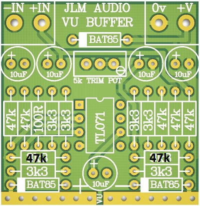
VU buffer PCB measures 1.45" (36.8mm) x 1.5" (38mm)
Note 2. Since the VU buffer runs on a single power rail it will have a power on voltage jump which will show as a large deflection on the meters pointer.
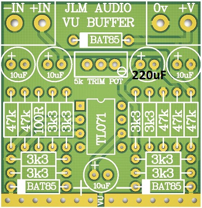
The size of the pointer deflection varies depending on meter type, voltage used, gain setting. This can be greatly reduced by slowing the rise of the half rail voltage on the VU buffer PCB.
This can be done by either changing the two 3k3 resistors shown below both to 47k or 100k. Or change the 10uF cap shown below to 100uF to 220uF 16v. Or doing Both changes. (VU buffer kits will have 2 extra 47k from Feb 2012)
Install IC socket semi circle cut out to the top as shown
Install Terminals now if not soldering wires directly to Power and In pads
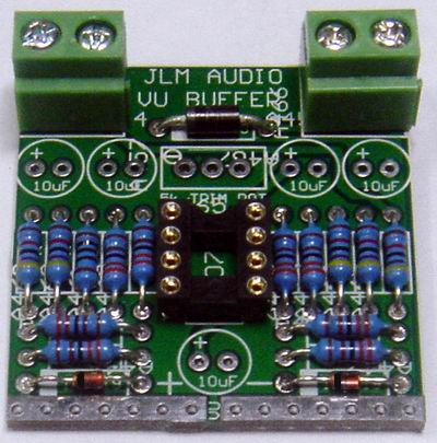
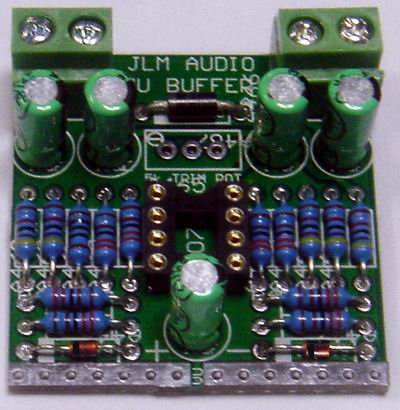
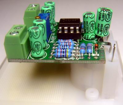
Fit Capacitors (Note they all face in the same direction)
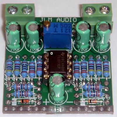
Fit Trim pot as PCB overlay shows and TL071 IC into socket as shown with pin 1 in the top left corner
(Note new PCB's have the trim pot with the screw in the bottom right corner and pot should be fitted as marked on the New PCB which is opposite to photo below)
The PCB uses the bottom edge to mount on to the VU meter + and - terminals.
Use any hole on the left for + and any hole on the right for -.
(If your meter has solder tags you can solder on directly or if there are 2 bolts use 2 cut off component legs to solder to the PCB and then wrap around the VU meter bolts.)
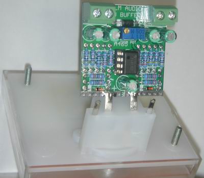
Fold PCB back behind VU meter
(Note 100uF cap mounted across SEW / FLASHSTAR meter to slow its response down to normal VU response)
If using the 12v regulated supply the Lamp or Blue led kit can be wired straight to the power for the VU buffer.
(Also the VU Buffer is protected against reverse voltage by the third diode at the top of the PCB)
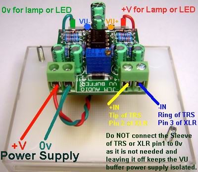
When connecting to a unbalanced signal +in goes to the signal and -in to the audio shield.
(A TRS socket will automatically do this when a TS unbalanced plug is plugged in to the TRS socket.)
BLUE LED
If you want to run the LED on more than 12volts you will need to add a series resistor.
Use this formula R = (V - 12) / 0.02.
So if you have a supply of say 24v regulated the blue LED would need a resistor =
R = (24 - 12) / 0.02 = 600ohm. So use 620ohm or 680ohm standard value resistor.
Will need to be a half watt type. [/color]
ORANGE / GREEN LAMP
If you want to run the Orange / Green Lamp on more than 12volts you will need to add a series resistor.
Use this formula R = (V - 12) / 0.08.
So if you have a supply of say 24v regulated the blue LED would need a resistor =
R = (24 - 12) / 0.02 = 200ohm. So use 220ohm standard value resistor.
Will need to be 1watt type or better use 100ohm 1watt in each wire to the lamp to spread the wasted heat better.
Audio Test Generator and Meters Great free Tone Generator and Meter software setup up your VU buffers and meters.
http://www.minorshill.co.uk/PC/Meters/S ... 20Test.zipjpg[/img]
Fit Capacitors (Note they all face in the same direction)
[img]httpcom/VU/VU%20BUFFER%20PCB%20low%20thump%201
47k = Yellow Violet Black red
3k3 = Orange Orange Black Brown
100R = Brown Black Black Black
Install resistors and diodes with there white or black stripes to the left
Top Diode can be any type 1N4001,2,4,7 or BAT85 or 1N5819 as it is only to stop reverse power wiring from damaging the opamp.
Bottom 2 diodes need to be Schottky BAT85 1N5819 etc or Germanium OA47, OA91 etc type for the meter to track correctly at low levels.
Note 1. When using a meter with internal rectifiers like our Nissei AL29 do the mod shown below to disable the VU buffer recitifier.
VU buffer PCB measures 1.45" (36.8mm) x 1.5" (38mm)
Note 2. Since the VU buffer runs on a single power rail it will have a power on voltage jump which will show as a large deflection on the meters pointer.
The size of the pointer deflection varies depending on meter type, voltage used, gain setting. This can be greatly reduced by slowing the rise of the half rail voltage on the VU buffer PCB.
This can be done by either changing the two 3k3 resistors shown below both to 47k or 100k. Or change the 10uF cap shown below to 100uF to 220uF 16v. Or doing Both changes. (VU buffer kits will have 2 extra 47k from Feb 2012)
Install IC socket semi circle cut out to the top as shown
Install Terminals now if not soldering wires directly to Power and In pads
Fit Capacitors (Note they all face in the same direction)
Fit Trim pot as PCB overlay shows and TL071 IC into socket as shown with pin 1 in the top left corner
(Note new PCB's have the trim pot with the screw in the bottom right corner and pot should be fitted as marked on the New PCB which is opposite to photo below)
The PCB uses the bottom edge to mount on to the VU meter + and - terminals.
Use any hole on the left for + and any hole on the right for -.
(If your meter has solder tags you can solder on directly or if there are 2 bolts use 2 cut off component legs to solder to the PCB and then wrap around the VU meter bolts.)
Fold PCB back behind VU meter
(Note 100uF cap mounted across SEW / FLASHSTAR meter to slow its response down to normal VU response)
If using the 12v regulated supply the Lamp or Blue led kit can be wired straight to the power for the VU buffer.
(Also the VU Buffer is protected against reverse voltage by the third diode at the top of the PCB)
When connecting to a unbalanced signal +in goes to the signal and -in to the audio shield.
(A TRS socket will automatically do this when a TS unbalanced plug is plugged in to the TRS socket.)
BLUE LED
If you want to run the LED on more than 12volts you will need to add a series resistor.
Use this formula R = (V - 12) / 0.02.
So if you have a supply of say 24v regulated the blue LED would need a resistor =
R = (24 - 12) / 0.02 = 600ohm. So use 620ohm or 680ohm standard value resistor.
Will need to be a half watt type. [/color]
ORANGE / GREEN LAMP
If you want to run the Orange / Green Lamp on more than 12volts you will need to add a series resistor.
Use this formula R = (V - 12) / 0.08.
So if you have a supply of say 24v regulated the blue LED would need a resistor =
R = (24 - 12) / 0.02 = 200ohm. So use 220ohm standard value resistor.
Will need to be 1watt type or better use 100ohm 1watt in each wire to the lamp to spread the wasted heat better.
Audio Test Generator and Meters Great free Tone Generator and Meter software setup up your VU buffers and meters.
http://www.minorshill.co.uk/PC/Meters/S ... 20Test.zipjpg[/img]
Fit Capacitors (Note they all face in the same direction)
[img]httpcom/VU/VU%20BUFFER%20PCB%20low%20thump%201