 Capturing Audio without Injury
Ph +617 38912244 or Skype jlm.audio or MSN / email joe@jlmaudio.com |
|||||||
| Home | Products | Kits | Reviews | Schematics | JLM Web Store | JLM Forum | Links |
| JLM
PM2000 CUE TO SOLO MOD
KIT
Features for JLM PM2000 CUE TO SOLO MOD KIT
|
|
|
Before you start
JLM PM2000 SOLO MOD
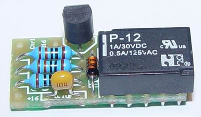
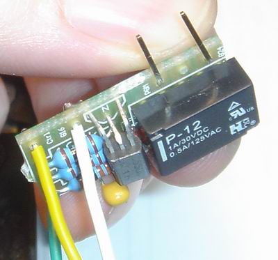
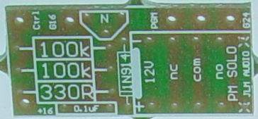
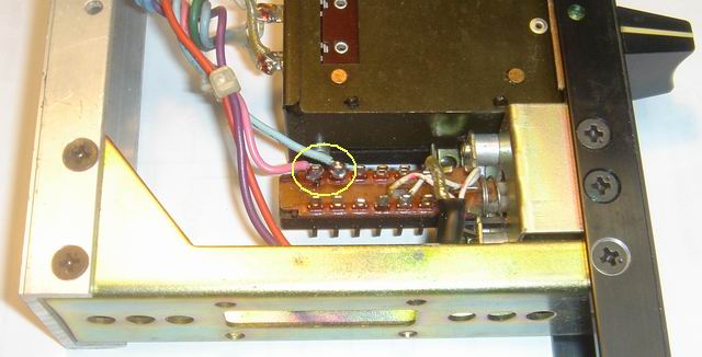
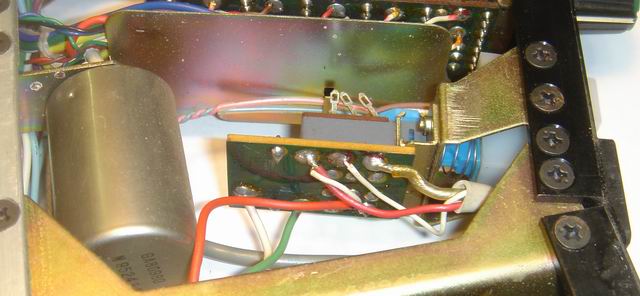
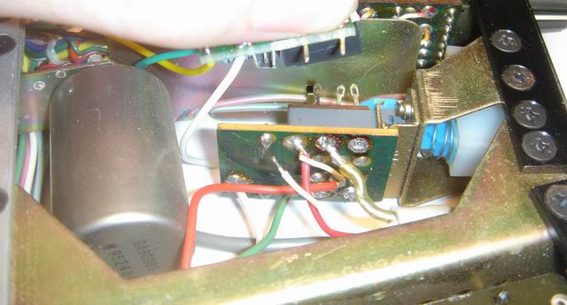
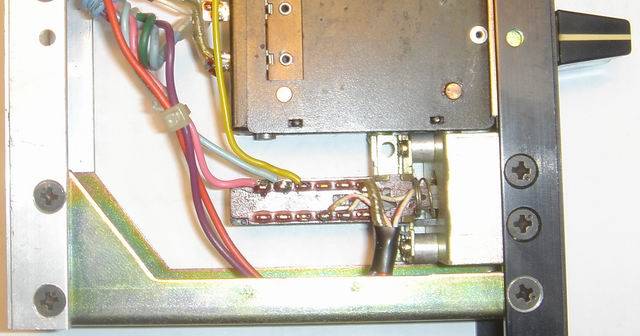
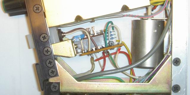
Firstly build the solo mod PCB, placing the parts as indicated by the PCB overlay and the photos here. You must bend the legs of the transistor so that it sits roughly flat with the top of the relay (see photo). You can also see the position of the colored wires in the photos. INSTALLATION OF THE MOD Note: to do this mod we have to re use several wires already soldered in the module. Be careful when you remove them not to melt or damage them much as some of them are not easy to replace. Use the minimal amount of heat you can and don't reheat any joints/wires more than necessary. Take it slow the first time and get a feel for how the mod goes together, and you'll save yourself time troubleshooting in the future. 1 Swap the pink and blue wires on the end two tags of the Cue switch. Don't try and unsolder them as you'll pull the tag out of the switch, just cut the wires as close as you can to the tags, then strip a little extra insulation and re tin them.
The amount of slack on these wires varies between modules, if you don't have enough you can usually unwrap them from the loom they're in and they will reach. When you're done the pink wire will be on the end tag of the switch.
2 Observe the PCB for the channel on/off switch. This is where the solo mod PCB will mount.
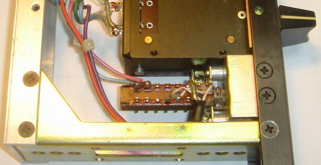
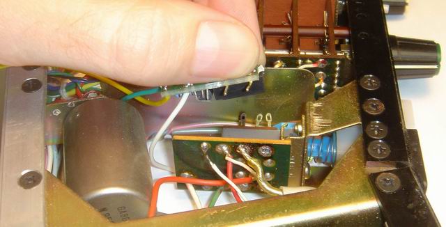
There are three pads on the top edge of this PCB with wire going to them. You need to take the wires off the right two pads, the right one having a thick shield wire (sometimes two depending on the module) and the middle one having a thin white signal wire on it. Once you have removed these wires, you have to suck the solder out of the holes in the PCB using a solder sucker.
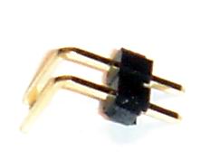
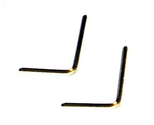
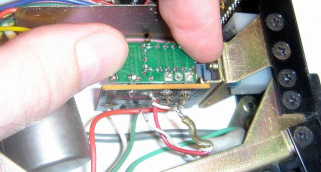
If you've never done this, practice it on some vero board before you try it on your module. You need to clear a large enough hole for some 1mm pins to fit through. *You need your hot melt glue gun ready for this next step* 3 Cut the black plastic holding the two right angle pins (included in your kit) together so you just have two bare right angle pins. Push the pins through the two square pad holes in the solo mod PCB (as shown in the photo) and hold them at the right angle with your thumb. Then poke the two pins through the holes that you've just cleared in the channel on/off PCB.
The relay should be flat against the grey pushbutton switch on the PCB, and you can roughly line up the pins so they go straight into the two holes. There should be about a 1mm gap between the two PCBs.
***Make sure the bent legs of the transistor on the solo mod PCB aren't touching the large 2watt resistor on the channel on/off PCB.*** Once you're confident the solo PCB is sitting in the right place, squeeze a small amount of hot melt glue onto the left hand edge of the two PCBs, joining them together. Hold it still until the glue has set then carefully remove your finger, as the glue isn't very strong and it only holding it there while you solder the pins.
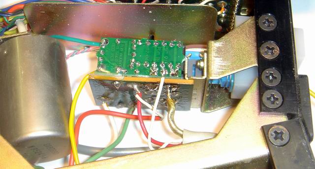
4 Solder the two right angle pins to the channel on/off PCB and the solo mod PCB. Trim the extra length off the pins, then solder the shield wire back where it was and the small white wire to the middle of the thee pads (the round one) on the solo mod PCB.
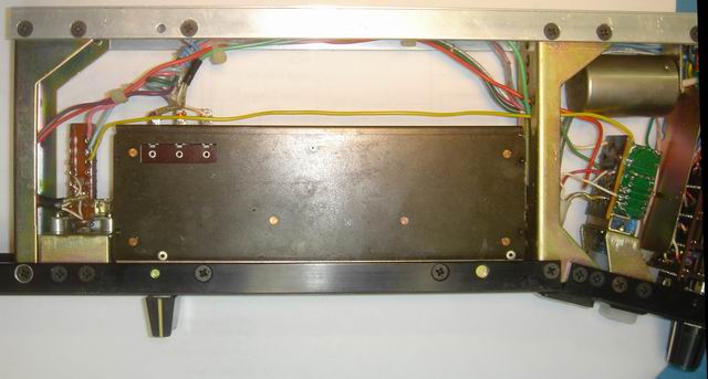
5 Feed the yellow wire from the solo mod PCB through the chassis frame and down past the fader to the Cue switch. Trim it to the right length then solder it to the third tag from the end of the Cue switch, next to the blue wire. The switch should now have three wires on that end which from left to right are pink, blue then yellow.
6 Turn the module over and observe the other side of the channel on/off switch PCB. You need to connect the white and green wires from the solo mod PCB to the pads on the channel on/off PCB that have the white and green wires going to them. You might need to add some fresh solder to the pads to make the wires solder on properly.
Your channel is now modded for true solo in place. You can plug it into the desk and test it even if the other channels aren't modded. If you hit the Cue button on any other channel and if the solo mod is working on your newly modded channel, it will mute. As you add more modded channels you'll be able to use solo in place with them together. Congratulations on your DIY skills, and enjoy this great new feature of your PM2000! |
